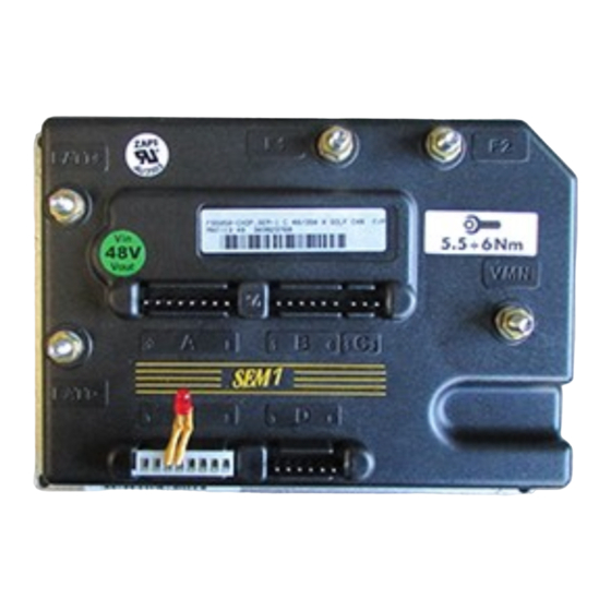
Advertisement
Quick Links
MENU
1
Introduction to the ZAPI-MOS family ........................................................... 4
2
General characteristics ................................................................................. 5
3
Installation.................................................................................................... 11
4
Programming & Adjustments using Digital Console ............................... 15
5
SEM-1C: cabling and configuration ........................................................... 17
6
SEM-1C Diagnostics .................................................................................... 27
7
Recommended Spare parts for SEM-1C .................................................... 37
8
Periodic Maintenance to be repeated at times indicated ......................... 38
INDEX
Page 1
Advertisement

Summary of Contents for Zapi SEM-1C
-
Page 1: Table Of Contents
General characteristics ................. 5 Installation....................11 Programming & Adjustments using Digital Console ....... 15 SEM-1C: cabling and configuration ............17 SEM-1C Diagnostics ..................27 Recommended Spare parts for SEM-1C ............ 37 Periodic Maintenance to be repeated at times indicated ......38 Page 1... - Page 2 MENU SIGNED IN APPROVAL COMPANY DEPT. SERVICES MANAGEMENT EXECUTIVE AD0ZP0CA February 2000 Page 2...
- Page 3 MENU LEGEND COLOUR CODES (SINGLE COLOURS) Page 3...
-
Page 4: Introduction To The Zapi-Mos Family
MENU 1 INTRODUCTION TO THE ZAPI-MOS FAMILY - Optimum level of protection. The design has been derived from: The communication protocol will continue to evolve, thereby offering increas- ing possibilities of interaction and expansion. For this reason, the Zapimos family offers a standard dialogue mode with external systems. This allows... -
Page 5: General Characteristics
MENU 2 GENERAL CHARACTERISTICS 2.1 TECHNICAL SPECIFICATION 2.2 CONTROL UNITS 2.2.a Microswitches Ω Page 5... - Page 6 MENU 2.2.b Potentiometer Ω Ω Page 6...
- Page 7 MENU 2.3 SAFETY & PROTECTION FEATURES - Connection Errors : - Thermal Protection : - Low Battery Charge : - Protection against accidental Start up : - Protection against uncontrolled movements : - Main / Line Contactor : - External Agents : 2.4 DIRECTION ORIENTATION Page 7...
- Page 8 MENU 2.5 OPERATIONAL FEATURES Page 8...
- Page 9 MENU 2.6 SEM-1C CHOPPER DIAGNOSIS 2.7 THERMAL CONSIDERATIONS Page 9...
- Page 10 MENU 2.8 GENERAL INSTRUCTIONS AND PRECAUTIONS Ω Ω Page 10...
-
Page 11: Installation
MENU 3 INSTALLATION 3.1 CONNECTION CABLES 3.2 CONTACTORS 3.3 FUSES Page 11... - Page 12 MENU 3.4 DESCRIPTION OF SEM-1C CONNECTORS. PIN REFERENCE DESCRIPTION Page 12...
- Page 13 MENU PIN REFERENCE DESCRIPTION 3.5 DESCRIPTION OF POWER CONNECTIONS +BATT -BATT F1, F2 Page 13...
- Page 14 MENU 3.6 MECHANICAL DRAWING & DIMENSIONS Page 14...
-
Page 15: Programming & Adjustments Using Digital Console
MENU 4 PROGRAMMING & ADJUSTMENTS USING DIGITAL CONSOLE 4.1 ADJUSTMENTS VIA CONSOLE Pay attention to the polarity of the Console Connector when connecting to the chopper. The bevel on the connector should be uppermost. 4.2 DESCRIPTION OF CONSOLE & CONNECTION Page 15... - Page 16 MENU 4.3 DESCRIPTION OF STANDARD CONSOLE MENU Page 16...
-
Page 17: Sem-1C: Cabling And Configuration
MENU 5 SEM-1C: CABLING AND CONFIGURATION 5.1 POWER DIAGRAM Page 17... - Page 18 MENU 5.2 CONNECTIONS Page 18...
- Page 19 MENU 5.3 DESCRIPTION OF PROGRAMMABLE FUNCTIONS (OPTIONS). Page 19...
- Page 20 MENU Page 20...
- Page 21 MENU 5.4 DESCRIPTION OF PARAMETERS THAT MAY BE PROGRAMMED ACC. DELAY DECELER DELAY RELEASE BRAKING INVERSION BRAKING SOFT BRAKING SOFT ACCEL. CUTBACK SPEED 1 CUTBACK SPEED 2 H&S CUTBACK 10 MAX SPEED FORW 11 MAX SP FORW FINE 12 MAX SPEED BACK 13 MAX SP BACK FINE 14 COMPENSATION 15 MAXIMUM CURRENT =...
- Page 22 MENU 17 WEAK DROPOUT 18 FIELD NOM. CURR. 19 CREEP SPEED Page 22...
- Page 23 MENU 5.5 TABLE OF ADJUSTMENTS P R O G R A M M E D L E V E L PA R A M E TE R S U N IT Page 23...
- Page 24 MENU Page 24...
- Page 25 MENU 5.6 SEM-1C TRACTION STANDARD WIRING DIAGRAMS Page 25...
- Page 26 MENU 5.7 SEQUENCE FOR SEM-1C TRACTION SETTINGS. Page 26...
-
Page 27: Sem-1C Diagnostics
MENU 6 SEM-1C DIAGNOSTICS Page 27... - Page 28 MENU 6.1 ANALYSIS OF ALARMS DISPLAYED ON THE CONSOLE Page 28...
- Page 29 MENU Page 29...
- Page 30 MENU Page 30...
- Page 31 MENU 6.2 TESTER DESCRIPTION OF THE FUNCTIONS 1) BATTERY VOLTAGE: 2) MOTOR VOLTAGE: 3) MOTOR CURRENT: 4) FIELD CURRENT: 5) VMN: 6) TEMPERATURE: 7) ACCELERATOR: 8) FORWARD SWITCH: 9) BACKWARD SWITCH: 10) HANDLE/SEAT SWITCH: 11) QUICK INVERSION: 12) CUTBACK SWITCH 1: 13) CUTBACK SWITCH 2: Page 31...
- Page 32 MENU Page 32...
- Page 33 MENU 6.3 DESCRIPTION OF THE CONSOLE SAVE FUNCTION SAVE PARAM RESTORE Page 33...
- Page 34 MENU 6.4 DESCRIPTION OF CONSOLE RESTORE FUNCTION. Page 34...
- Page 35 MENU 6.5 DESCRIPTION OF ALARMS MENU. Page 35...
- Page 36 MENU 6.6 DESCRIPTION OF CONSOLE PROGRAM VACC FUNCTION Page 36...
-
Page 37: Recommended Spare Parts For Sem-1C
MENU 7 RECOMMENDED SPARE PARTS FOR SEM-1C Part Number Description Page 37... -
Page 38: Periodic Maintenance To Be Repeated At Times Indicated
MENU 8 PERIODIC MAINTENANCE TO BE REPEATED AT TIMES INDICATED 3 months. 3 months. 3 months. 3 months. 3 months. Remember that Battery Powered Machines feel no pain. NEVER USE A VEHICLE WITH A FAULTY ELECTRONIC CONTROLLER. Page 38... - Page 39 MENU COSTRUZIONE APPARECCHIATURE ELETTRONICHE - OLEODINAMICHE - INDUSTRIALI 42028 - POVIGLIO - (R.E.) - Via Parma, 59 - ITALIA Tel. +39 0522 960050 (r.a.) - Fax +39 0522 960259 - e-mail: infozapi@tin.it INSTALLATION AND USER MANUAL CHOPPER SEM-1C...

Need help?
Do you have a question about the SEM-1C and is the answer not in the manual?
Questions and answers