Table of Contents
Advertisement
Quick Links
Advertisement
Table of Contents

Related Manuals for NexTraq VT-2200


Summary of Contents for NexTraq VT-2200
- Page 1 The NexTraq VT-2200 Installation Guide...
- Page 2 NexTraq. Information and specifications contained in this document are subject to change without notice and do not represent commitments on the part of NexTraq. Under copyright laws, no part of this installation guide may be reproduced or transmitted in any form or by...
-
Page 3: Table Of Contents
Contents Introduction ..............................4 VT-2200 Hardware ............................4 VT-2200 Wiring Diagrams ........................6 Equipment and Tools ..........................6 Antennas ................................7 Installation Types........................... 7 Vehicle Wiring ............................10 VT-2200 Location ............................. 12 Post-Installation Testing......................13 Installation Troubleshooting ....................14 Appendix A – Technical Specifications ................. 16... -
Page 4: Introduction
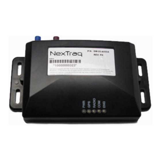
Introduction Following the purchase of VT-2200, there will be several factors to consider prior to its installation, including placement of the VT-2200 hardware and the selection and placement of the antenna(s). This installation guide is designed to provide instructions for the installation of the VT-2200 hardware for use with the NexTraq™... - Page 5 Fig. 1 – VT-2200 External mounting tabs are provided that allow VT-2200 to be secured to the chassis of the vehicle. If you are replacing a Wahoo 2, VT-2200 will fit in the area you have the Wahoo 2 secured. Additional equipment is required to properly mount the VT-2200 hardware and is provided in the installation kit for each VT-2200.
-
Page 6: Vt-2200 Wiring Diagrams
Black No Connect Connect Ignition White Battery Fig – 2 -Schematic of VT-2200 Equipment and Tools The following is a general list of tools and supplies required for a VT-2200 installation: Recommended Equipment Recommended Supplies Digital Volt and Ohm Meter (DVOM) -
Page 7: Antennas
Great care should be taken before installing the antennas. The standard antenna type used for the VT-2200 is a combination antenna. Two FAKRA connectors provide connection for GPS (blue) and GSM (violet). - Page 8 for cellular and GPS. It is recommended that the antenna have a view of at least 40 percent of the sky. The antenna needs to be mounted as horizontal as possible. The antenna should not be mounted behind windscreens, ladder racks or other radio transmission antennas. Fig.
- Page 9 Fig. 5 – Dashboard Mount Covert Installation When mounting a covert installation, care should be taken not to mount that antenna shielded by metal. However, it can be mounted on non- metallic materials such as plastic, fiberboard, fiberglass, etc. The antenna orientation should be that the top part of the antenna...
-
Page 10: Vehicle Wiring
Vehicle Wiring The 4-pin Molex connector on the back of VT-2200 contains the power, ground and ignition leads. The supplied power cable plugs into the Molex connector. The opposite end of the cable has a black wire for ground, a red wire for vehicle power and a white wire for vehicle ignition. - Page 11 A constant power source is essential in the retention of GPS data inside VT-2200, and is required. Be sure to verify that the power source you have chosen will work when the vehicle is not running, and the keys are removed. Verify a 5-amp fuse is inline with the power and ignition lead.
-
Page 12: Vt-2200 Location
The availability of a constant 12-volt power supply • In most vehicles, the VT-2200 can be placed inside or underneath the dashboard. The vehicle’s radio can be removed and the unit placed behind the radio. A kick plate can be removed and the unit can be safely secured to a firewall or zip-tied onto a permanent fixture. -
Page 13: Post-Installation Testing
Fig. 8 - VT-2200 Placement Connect the radio, GPS and power cables to VT-2200. Wrap any extra cable neatly with tie-wraps or electrical tape. Replace any paneling or molding that was removed in the running of any antenna wires or power cable. -
Page 14: Installation Troubleshooting
VT-2200. When VT-2200 is operating correctly, there should be a solid blue light on PWR, GPS and COM. Note: the radio LED will flicker while transmitting. - Page 15 COM light not on or blinks. Check GSM antenna connections. • Ensure that nothing obstructs the antenna such as metallic • sunscreens. Make sure VT-2200 is within the AT&T coverage map. • Reset power. • Ignition light is not on when vehicle is switched on.
-
Page 16: Appendix A - Technical Specifications
Appendix A – Technical Specifications The VT-2200 GPRS device is the latest hardware component from NexTraq that enables vehicle location and tracking through the NexTraq™ platform. ARM Processor Digital Inputs/Outputs • • GSM/GPRS Modem Serial Port Data Communications • •... -
Page 17: Appendix B - Installation Notes
As for mounting the VT-2200, it only comes with 3’ of power cable so the unit must be placed within the vicinity of your power connections.
Need help?
Do you have a question about the VT-2200 and is the answer not in the manual?
Questions and answers