
Related Manuals for Putzmeister SP11 LMR


Summary of Contents for Putzmeister SP11 LMR
- Page 1 Operating Instructions Translation of the original Operating Instructions for machine operator and maintenance staff always keep by the machine Motar machine SP11 LMR Machine no. Rev. 00- -0412 PMM_365375026...
- Page 2 Putzmeister Postfach 2152 07127 / 599–0 07127 / 599 743 Internet: Mörtelmaschinen D–72629 Aichtal www.putzmeister.de GmbH Max–Eyth–Str. 10 Hotline: e- -mail: D–72631 Aichtal (07127) 599- -699 pmm@pmw.de...
-
Page 3: Table Of Contents
Contents About these Operating Instructions Foreword ..........1 —... - Page 4 Contents 2.15 Hydraulic and pneumatic equipment ....2 — 19 Check ..........2 —...
- Page 5 Contents General Technical Description Machine versions ........3 —...
- Page 6 Contents Transport, Set-up and Connection Transport and driving ....... . . 4 —...
- Page 7 Contents Starting up Checks ..........5 —...
- Page 8 Contents Operation Requirements ........6 —...
- Page 9 Contents Maintenance Maintenance intervals ....... . . 8 — Other risks during maintenance work .
- Page 10 Contents 46- -030 Replacing the screw conveyor ....8 — 79 52- -008 High-pressure cleaner ..... . . 8 —...
-
Page 11: About These Operating Instructions
In this chapter you will find notes and information that will help you use these Operating Instructions. Do not hesitate to contact us if you have any queries: Putzmeister Mörtelmaschinen GmbH Postfach 2152 D-72629 Aichtal, Germany Tel: +49 (0)7127 599-0 Fax: +49 (0)7127 599-743 Internet: http://www.moertelmaschinen.de... -
Page 12: Foreword
About these Operating Instructions 1.1 Foreword These Operating Instructions are intended to familiarise the user with the machine and to assist him in using the machine properly in va- rious possible applications. The Operating Instructions contain important information on how to operate the machine safely, properly and economically. - Page 13 Operating Instructions were printed. These operating instructions are not covered by the Amendment Ser- vice of Putzmeister Mörtelmaschinen GmbH. Alterations may be made to these operating instructions without prior notification. The contents of this document may not be reproduced, even in part, without our written permission.
-
Page 14: Icons And Symbols
About these Operating Instructions 1.2 Icons and symbols The following icons and symbols are used in the Operating Instruc- tions: " Action symbol Text following this symbol describes tasks which you are required to work through, generally in the sequence shown from top to bottom. ⇒... - Page 15 About these Operating Instructions Danger Particular specifications or instructions and prohibitions with regard to the prevention of personal injury or significant damage are introdu- ced with the pictogram illustrated, the word ”Danger” written in bold and a line. The associated text is written in italics and is closed off with a line.
-
Page 17: Safety Regulations
Safety Regulations 2 Safety Regulations This chapter summarises the most important safety regulations. This Chapter must be read and understood by all persons who handle the machine. The various regulations are also repeated once more at the appropriate points in the Operating Instructions. Notes Special safety regulations may be necessary for some tasks. -
Page 18: Principle
The machine may not be sold on without the accompanying documentation under any circumstances. Reporting an onwards sale or acquisition to Putzmeister ensures that you will be sent any information relating to modifications or in- novations relevant to safety, and you will also be eligible for technical consultancy from our works. -
Page 19: Designated Use
Safety Regulations 2.2 Designated use The machine has been built in accordance with the state of the art and recognised safety rules. Nevertheless, its use may constitute a risk to life and limb of the operator or of third parties, or cause da- mage to the machine and to other property. -
Page 20: Use Contrary To The Designated Use
The values quoted on the rating plate and in the technical data are the maximum permissible values. The control and safety settings made at Putzmeister Mörtelmaschi- nen GmbH must not be changed. The machine must not be operated with deactivated, modified or de- fective safety devices. -
Page 21: Liability
Please therefore ensure that the necessary caution prevails. Exclusion of liability We state here expressly that Putzmeister Mörtelmaschinen accepts no liability for damage arising from incorrect or negligent operation, servicing or maintenance or as a result of use contrary to the desi- gnated use. -
Page 22: Personnel Selection And Qualifications
Safety Regulations 2.5 Personnel selection The machine may only be operated or serviced independently by persons who and qualifications - - have reached the legally required age; - - are physically capable (rested and not under the influence of alco- hol, drugs or medication);... -
Page 23: Sources Of Danger
Safety Regulations 2.6 Sources of danger Never reach into moving machine components, whether the machine is running or switched off. Always switch off the main switch first. Take note of the warning plate. In the event of malfunctions, stop the machine immediately and se- cure it. -
Page 24: Safety Equipment
Safety Regulations 2.7 Safety equipment Never remove or modify safety devices on the machine. Any safety devices removed for set-up, maintenance or repair purpo- ses must be refitted and checked immediately upon completion of the maintenance and repair work. Safety devices must only be repaired, adjusted or replaced by tech- nically qualified experts. -
Page 25: Personal Protective Clothing
Safety Regulations 2.8 Personal protective To reduce the risk to life and limb, the following personal protective clothing must be worn whenever necessary or required by regula- clothing tions. Protective helmet, protective gloves and safety boots are always specified for all persons working at or with the machine. Personal protective clothing must at least comply with the specified standards. - Page 26 Safety Regulations Protective goggles Protective goggles protect your eyes against injuries from concrete spatters or other particles. (EN ISO 166; Personal eye protection - - Specifications) Safety harness A safety harness protects you against falling when you are working on scaffolding, bridges or in similar areas. (EN ISO 361;...
-
Page 27: Risk Of Injury - - Residual Risk
Safety Regulations Risk of injury - - resi- The machine has been built in accordance with state of the art tech- nology and recognised safety rules. Nevertheless, its use may con- dual risk stitute a risk to life and limb of the operator or of third parties, or cause damage to the machine and to other property. -
Page 28: Risk Of Crushing And Bumping
Safety Regulations 2.10 Risk of crushing and During the following machine operating modes: - - Set-up bumping - - Starting up - - Operation - - Cleaning, Troubleshooting, Maintenance - - Decommissioning there is a risk of injury through crushing or bumping. Transporting the When loading the machine with a crane onto a transport vehicle, the machine... -
Page 29: Assembly Of The Auger Pump
Safety Regulations Assembly of the auger There is a risk of crushing when installing the auger pump. pump Depending on the mounting position of the stator or auger barrel, these may turn until they rests against the stop when the machine is switched on. -
Page 30: Electrical Contact
Safety Regulations 2.11 Electrical contact The control cabinet, electrical wiring and drive motor pose a risk of fatal injury from electrical contact during the following: - - Setting up - - Operation - - Cleaning, Troubleshooting, Maintenance - - Decommissioning All electrical assemblies are protected as standard, as per IEC 60204 Part1 or DIN 40050 IEC 144 in accordance with protec- tion category IP 54. -
Page 31: Risk Of Burns And Scalding
Safety Regulations 2.12 Risk of burns and The drive motor and the frame pose a risk of burns during the follo- wing: scalding - - Starting up - - Operation - - Cleaning, Troubleshooting, Maintenance - - Decommissioning Risk of burns. Danger The control cabinet switches off the drive motor in the event of over- heating. -
Page 32: Coolant
Safety Regulations Coolant Particular care must be taken when handling the end cover of the water cooler. The end cover must be sealed and closed firmly. Danger Never remove the cooler end cover if the drive motor is running or is still hot. -
Page 33: Starting Up
Safety Regulations 2.13 Starting up When starting the machine at temperatures below +10 _C, a va- cuum may develop in the hydraulic hoses due to the increased oil viscosity. Under unfavourable conditions, this may damage the hy- draulic fluid circuit in the machine. Danger The hydraulic fluid circuit may be blocked! To avoid damage at temperatures below +10 _C, the machine... -
Page 34: Blockage
Safety Regulations 2.14 Blockage Avoid blockages. A well cleaned and leak-tight delivery line is the best assurance against formation of a blockage! Blockages conside- rably increase the risk of accident. Always use cement grout for initial pumping. Danger Never attempt to blow out a blockage with compressed air. There is a risk of fatal injury because the delivery line can burst! Injury through the force of bursting couplings, pipelines or blockages flying out of delivery lines. -
Page 35: Hydraulic And Pneumatic Equipment
Safety Regulations 2.15 Hydraulic and pneu- Work on hydraulic equipment may be carried out only by persons having special knowledge and experience in hydraulic systems, who matic equipment can demonstrate to us appropriate certification of competence (certi- ficates of training). Couplings must be fitted to hoses by persons who possess the ne- cessary experience and equipment required for this task. -
Page 36: Dumping Pressure
Safety Regulations Regular inspections are specified as part of the safety inspections of the machine. Bursting lines present a risk of injury. The manufacturer accepts no responsibility for damage resulting from the use of worn or defective components. Do not repair damaged hydraulic lines, but replace them. Replace damaged or saturated hydraulic hoses immediately. -
Page 37: Place Of Work
Safety Regulations 2.16 Place of work The workplace is the area in which people must remain in order to carry out the work. Operator The place of work of the operator during use of the machine is at the operating panel of the machine. 2.17 Working area The working area is the area where work is carried out with the deli- very line, or the machine is filled with material. -
Page 38: Environmental Protection
Spare parts from original equipment manufac- turers guarantee this. Use only original spare parts. Putzmeister Mörtelmaschinen GmbH accepts no liability for damage caused as a result of using non-original spare parts. The machine should only be stored in a dry, clean and well ventilated 2.22 Storing the machine... -
Page 39: Sound Emissions
Safety Regulations 2.23 Sound emissions Sound emissions are generated during the following operating mo- des at the machine: - - Starting up - - Operation - - Cleaning, Troubleshooting, Maintenance - - Decommissioning Refer to the technical data for the sound pressure level value in the vicinity of the machine. -
Page 40: Place Of Work
Safety Regulations 2.24 Place of work The place of work is the area in which people must remain in order to carry out the work. Machine operator The place of work of the machine operator during operation is at the operating panel on the machine. -
Page 41: Accessories
Notes Accessories that are not included in the scope of supply delivered with the machine are supplied by Putzmeister and can be purchased through Parts Sales. Please refer to the delivery note for a list of accessories supplied. -
Page 42: Injuries Through Unauthorised Starting Or Use Of The Machine
Safety Regulations 2.29 Injuries through unau- During the following operating modes at the machine: - - Starting up thorised starting or - - Operation use of the machine - - Cleaning, Troubleshooting, Maintenance - - Decommissioning there is a risk due to unauthorised starting or use of the machine. Always secure the machine against unauthorised starting before lea- ving the work area. -
Page 43: Safety-Related Parts (Srp)
Safety-related parts (SRP) much only be maintained, repaired and replaced by authorised Putzmeister specialists. If a safety-related part (SRP) is incorrectly maintained, repaired or replaced, this can result in safety functions not operating correctly. -
Page 44: Spare Parts
Spare parts must comply with the technical requirements specified by the manufacturer. Spare parts from original equipment manufac- turers guarantee this. Use only original spare parts. Putzmeister Mörtelmaschinen GmbH accepts no liability for damage caused as a result of using non-origi- nal spare parts. -
Page 45: General Technical Description
The following data can be found on the rating plate: - - Machine model - - Machine number Notes The machine number is allocated by Putzmeister Mörtelmaschinen GmbH. Each machine number is only allocated once. This means that the machine number identifies each individual machine. 3 — 1... - Page 46 General Technical Description 3.2 Machine designation Your machine is an SP11 auger pump from Putzmeister Mörtelmaschinen GmbH. 3.3 Machine model The machine model designation is printed on the cover sheet of the operating instructions and on the rating plate of your machine.
-
Page 47: Machine
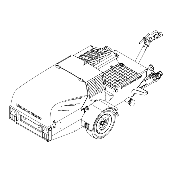
General Technical Description 3.5 Summary Below you will find a summary of the most important components, which are described on the following pages. Machine Item Designation Towing gear Socket Air valve fitting Rating plate Hopper Hood Control cabinet Operating elements Axle and wheels Lifting mixer unit Support foot... -
Page 48: Engine Compartment
General Technical Description Engine compartment Item Designation Engine Return line suction filter Hydraulic fluid reservoir Radiator Expansion tank for coolant Dry air filter Battery Compressor Fuel tank filler neck Fuel filter Hydraulic pump Hydraulic control block 3 — 4 02_0694_1202GB... -
Page 49: Dimensions
General Technical Description 3.6 Technical data The following technical data and characteristics relate to the SP11. SP 11 LMR Dimensions Length: 3480 mm Width: 1420 mm Height: 1162 mm Fill height: 750 mm Weight Permitted gross weight: 750 kg Permitted drawbar load: max. -
Page 50: Performance Data
General Technical Description SP 11 LMR Performance data 3-cylinder diesel engine Engine: 16.3 kW at 2600 rpm Compressor: 2 cylinders; 3.5 bar; 400 min. Auger pump: 2 L 6 (depending on model) Delivery rate: 0 - 55 min. Delivery pressure: 25 bar Max. -
Page 51: Fluid Capacities
General Technical Description SP 11 LMR Fluid capacities Engine oil volume 5.3 l with filter change Engine oil: Refer also to the documentation pro- vided by the engine manufacturer. Diesel fuel Fuel: capacity approx. 25 l Compressor fluid Compressor oil: volume approx. -
Page 52: Rating Plate
General Technical Description 3.7 Rating plate The most important machine data is shown on the rating plate. Item Designation Model (machine model) Year of manufacture Maximum delivery pressure [bar] Hydraulic pressure [bar] (maximum fluid pressure in the hydraulic system) Voltage [V] Frequency [Hz] Power [kW] Licence number... -
Page 53: Sound Power Level
General Technical Description 3.8 Sound power level In accordance with Directive 2000/14/EC the sound power level emit- ted by the machine is given below. Next to the rating plate on the machine there is the plate shown in the picture below which gives the machine’s sound power level mea- surement. -
Page 54: Safety Equipment
General Technical Description 3.9 Safety equipment The following is a list of installed safety equipment on the machine. Danger Only operate the machine with the safety equipment fitted and fully functional. EMERGENCY STOP but- The control cabinet of the machine accommodates an EMERGENCY STOP button. -
Page 55: Hood Safety Device
General Technical Description Hood safety device The machine is fitted with a hood safety device. If the hood is ope- ned during operation, a safety switch is actuated and the drive motor switches off immediately. Notes You must close the hood after carrying out the check and test opera- tions. -
Page 56: Functional Description
General set-up of the Putzmeister machines are easy to assemble and operate. In spite of machine this, certain precautionary measures must be taken when operating the machine to ensure that the wear parts have as high a life limit as possible. -
Page 57: Control Cabinet
General Technical Description 3.11 Control cabinet The machine is operated and controlled from the control cabinet. Heavy current Work on the machine’s electrical system and equipment may only be carried out by a qualified electrician or by instructed persons under the supervision and guidance of a qualified electrician in accor- dance with electrotechnical rules and regulations. -
Page 58: Engine
General Technical Description Operating / control Item Function / display elements Master switch Power supply OFF / ON (under hood) Ignition switch Starts the engine Rocker switch High-pressure cleaner ON / OFF Toggle switch Mixer unit BACKWARDS - - 0 - - FORWARDS Toggle switch Auger pump BACKWARDS - - 0 - - FORWARDS... - Page 59 General Technical Description 3.12 Engine The machine is powered by a 3-cylinder diesel engine. Different models available Item Designation Oil dipstick Oil filler Engine oil filter Oil drain plug (obscured) The engine has different performance data, depending on the mo- del.
- Page 60 General Technical Description 3.13 Auger pump The auger pump built into the machine is called a displacement pump. An auger (rotor) rotates inside a fixed auger barrel (stator). The auger consists of a highly wear-resistant, very hard metal alloy and the auger barrel of a multi-notched steel sleeve with vulcanised elastic rubber core.
- Page 61 General Technical Description 3.14 Hydraulic control The machine is equipped with a hydraulic constant-displacement pump. The hydraulic fluid supply is sufficient to power several functions si- multaneously. The variable output auger pump, the mixing mechanism, the mixer lifting device (depending on model) and the high-pressure cleaner (optional) are driven via 2 separate hydraulic circuits, depending on the model of the machine.
-
Page 62: Hydraulic Control
General Technical Description Hydraulic control block The SP11 has an electromagnetic hydraulic control block with valves SP11 for the auger pump and the mixer. Output can be regulated using the output controller under the control cabinet. Notes Reducing the output with the output controller will not reduce the en- gine’s power. -
Page 63: Compressor
General Technical Description 3.15 Compressor A 2-cylinder compressor has been integrated into the SP11 to gene- rate the air required to spray the mortar. This is driven by V-belts from the diesel engine. 2-cylinder compressor The air generated is transported through the air battery and an air hose to the spray gun. -
Page 64: Air Valve Fitting
General Technical Description 3.16 Air valve fitting The air valve fitting is located on the front of the machine, viewed in the direction of travel. Item Designation Valve for spray air Air hose connector Air valve for controlling the pump Air is channelled from the compressor into the air valve fitting for spray gun operation. -
Page 65: Spray Gun
Stop cock (depending on model) Air-regulation cock (depending on model) If your machine is not fitted with these components, consult your dealer or local Putzmeister Mörtelmaschinen GmbH representative as to how and whether you should upgrade your machine. 3 — 21... -
Page 66: Dust Extraction (Option)
General Technical Description 3.18 Dust extraction As an option, the machine can be fitted with a dust extraction sy- stem. (option) Item Designation Mixer cover Dust extraction Dust is extracted above the filling opening on the mixer. Caution Only regular cleaning will guarantee that the dust extraction system functions correctly. -
Page 67: High-Pressure Cleaner (Option)
General Technical Description 3.19 High-pressure cleaner A hydraulically driven high-pressure cleaner can be installed as an option. (option) The high-pressure cleaner is used to clean the outside of the ma- chine with pressurised water. Caution The high-pressure cleaner must never be operated without water. Make sure that the water inlet is connected correctly. - Page 68 General Technical Description Wear all the necessary personal protective equipment during opera- tion. Refer also to chapter: ”Safety regulations” - - section: ”Protective equipment”. Danger Waterproof protective equipment only provides protection from spray water and splash particles. In the case of direct contact with the high-pressure water jet, protective clothing does not provide suffi- cient protection from injury.
-
Page 69: Transport, Set-Up And Connection
Star- ting up the machine will not be described until the chapter ”Starting up”. Putzmeister trailer machines may only use public roads if properly 4.1 Transport and driving approved. They are subject to Road Traffic laws when being towed in road traffic. -
Page 70: Transporting The Machine
Transport, Set-up and Connection 4.2 Transporting the ma- If you wish to load the machine onto a suitable transport vehicle, jack rings must be fitted on the machine. chine Use the slinging points provided on the machine when loading it by crane. -
Page 71: Machine Transport Position
Transport, Set-up and Connection 4.3 Machine transport Set the machine to transport position before towing on the open road. position Machine lifting mixer unit Lifting mixer unit in transport position Check that the machine is in transport position: - - The lifting mixer unit is lowered. - - The mixer cover is closed and secure. -
Page 72: Before A Journey
Transport, Set-up and Connection 4.4 Before a journey The following points must be observed before the machine can be moved by a tractor unit on the open road: - - The towing gear is fully functional. - - The machine is in transport position. - - The hood must be tightly closed. -
Page 73: Towing Gear
Transport, Set-up and Connection Towing gear The tractor unit must be equipped with a trailer coupling complying with DIN specifications. The adjustable drawbar must be set up in such a way that the trailer coupling ring may be inserted horizontally into the trailer coupling. -
Page 74: Adjusting The Towing Gear
Transport, Set-up and Connection Adjusting the towing To adjust the towing gear, proceed as follows: gear Symbolic illustration Item Designation Spring pin Locking toggle " Pull the spring pin(1) from the locking toggle(2). " Release the locking toggle and turn it as far as the stop. ⇒... -
Page 75: Ball Hitch
Transport, Set-up and Connection Ball hitch The ball hitch is equipped with a safety control display. This consists of clearly imprinted symbols, which are pasted over with a red- green-red label with the same symbols, and a pointer. Coupling the ball hitch To couple, place the opened ball hitch (X-position) on the ball of the tractor unit until it clearly audibly engages. - Page 76 Transport, Set-up and Connection Caution If the indicator is in the red “- ” area, then the ball hitch is not properly closed and the trailer must under no circumstances be driven. For further details, refer to the chapter: “Faults, Cause and Remedy” - - Section: “Chassis”.
-
Page 77: Disconnecting The Ball Hitch
Transport, Set-up and Connection Disconnecting the ball To disconnect the trailer, proceed as follows. hitch " Open hitch handle, pull up and then swivel forwards. ⇒ The ball hitch stays in the “open” position, in which the indi- cator points at the red area with the large “X”. Danger The trailer must never be driven in this condition. -
Page 78: Permitted Slewing Circle Of The Ball Hitch
Transport, Set-up and Connection Permitted slewing circle The swivel range of the ball hitch around the vehicle longitudinal axis of the ball hitch is max. +/- - 25˚. Horizontally, slewing angles within a range of +/- - 20˚ are possible. A slewing circle 20˚... -
Page 79: Lighting Equipment
Transport, Set-up and Connection 4.5 Lighting equipment The machine is fitted with lighting equipment. Notes The lighting equipment is designed to run off 12 V as standard. Item Designation Lighting equipment Power cable Connector Socket The vehicle registration plate is also located next to the lighting at the lighting equipment(1). -
Page 80: Selecting The Set-Up Site
Transport, Set-up and Connection 4.6 Selecting the set-up The set-up site of the machine is usually determined and appropria- tely prepared by the site management. site Notes The responsibility for setting up the machine safely falls on the ope- rator. 4.7 Set-up site require- Inspect the proposed site carefully and reject the set-up site if you have any doubts in respect of safety. -
Page 81: Setting Up
Transport, Set-up and Connection 4.8 Setting up The machine must be set up so that it is absolutely stable and secu- red against rolling. " Secure the machine against rolling by placing chocks under the wheels. " Apply the handbrake on machines with brake equipment. "... -
Page 82: Aligning The Machine
Transport, Set-up and Connection Aligning the machine Align the machine horizontally. Item Designation Support foot Crank " Wind down the support foot (1) using the crank (2) until the ma- chine is horizontal. Caution Wind the support foot back to its transport position before transpor- ting the machine. -
Page 83: Water Connections
Transport, Set-up and Connection 4.9 Water connections The following section describes how to connect the machine to the water supply. The water supply may only be connected as per DIN 1988 - - Techni- cal Rules for Water Installations, i.e. using installation type 1 back- flow preventers or an independent outlet (buffer tank with a booster pump). -
Page 85: Starting Up
Starting up 5 Starting up In this chapter you will find information on starting up the machine. The work steps for initial operation of the machine are described as well as how to prepare the machine for operation after a long break. There is also a description on how to check the condition of your ma- chine and how to carry out a test run with function checks. -
Page 86: Checks
Starting up 5.1 Checks Each time the machine is used, you should check the condition of your machine and carry out a test run including function checks. If you identify any defects during the checks, you must eliminate these (or have these eliminated) immediately. Visual checks Some important visual checks should be carried out before starting up the machine. -
Page 87: Operating Materials
Starting up Operating materials 10000700 Water, oil and fuel levels Danger Oils and other operating materials can pose a threat to health if they come into contact with the skin or similar. You must, therefore, always wear personal protective clothing and equipment when you are handling toxic, caustic or other operating materials that are injurious to health and always take note of the ma- nufacturer’s information. -
Page 88: Fuel Level
Starting up Fuel level The fuel level must be as close as possible to the “Max” marking. " Check the fuel level at the viewing window in the frame on the left of the machine exterior. " Top up the fuel if necessary. For further details, refer also to the chapter: “Starting up”... -
Page 89: Compressor Oil Level
Starting up Compressor oil level You can check the compressor oil level at the level indicator on the compressor. " Check the compressor oil level at the level indicator on the compressor. " Top up the compressor oil if necessary. Notes Do not top up the beyond the “Max”... -
Page 90: Coolant Level
Starting up Coolant level Check the coolant level at the expansion tank on the cooling system as follows: Notes The coolant level must be as close as possible to the “Max” marking. " Top up the coolant if necessary. The air side of the radiator can become clogged if the unit is opera- Checking cooling fins on the radiator ting in dusty conditions. -
Page 91: Refuelling The Machine
Starting up 5.2 Refuelling the Before starting up, check that there is sufficient fuel in the tank and, if necessary, top up with fuel via the filler neck. The machine can be machine filled with fuel via the filler neck when it has been shut down. Notes Always fill the tank in good time because otherwise you will have to vent the fuel line to the diesel engine. -
Page 92: Test Run
Starting up 5.3 Test run Carry out a test run before operating the machine. Start the engine to perform a test run. Some functions must be chek- ked while the machine is running. Notes Any defects found during these tests must be rectified immediately. A fresh inspection is necessary after every repair. - Page 93 Starting up " Close the hood again. Danger The machine must only be operated with the hood closed. " Switch off the auger pump at the “Auger pump BACKWARDS - - 0 - - FORWARDS” switch (2). Switch off the mixer at the “Mixer unit BACKWARDS - - 0 - - FOR- "...
- Page 94 Starting up Caution Preheat the engine no longer than necessary (max. 20 s)! Otherwise the spark plugs and starting solenoid could be damaged! " Then turn the ignition switch clockwise even further to start the engine. ⇒ The engine starts. ⇒...
-
Page 95: Function Checks
Starting up 5.4 Function checks Before using the machine, the following functions should be checked with the machine running. Notes You must close the hood after carrying out the check and test opera- tions. The machine may be operated only with the hood closed. Check whether all safety equipment are fitted and fully functional. -
Page 96: Function Check Of Emergency Stop Button
Starting up Function check of Check the operability of the EMERGENCY STOP button. EMERGENCY STOP button Press: lock EMERGENCY STOP Rotate: unlock EMERGENCY STOP " Start the drive motor. Refer also to the section: ”Starting the drive motor”. " Press the EMERGENCY STOP button. ⇒... -
Page 97: Function Check Of Hood Safety Device
Starting up Function check of hood The machine is fitted with a hood safety device. If the hood is ope- safety device ned while the drive motor is running, the hood switch triggers and the machine switches off. Danger A defective hood switch could appear to be safe, but in reality poses a danger. -
Page 98: Function Check Of The Protective Grille Cut-Out
Starting up Function check of the Check that the protective grille cut-out is fully functional. protective grille cut-out Item Designation Protective grille (different versions) Safety switch Notes The safety device at the protective grille (1) is equipped with a sa- fety switch (2) which switches off the mixing mechanism as soon as the protective grille is raised. - Page 99 Starting up Protective grille The auger pump is switched off by the protective grille cut-out on on the mixer the mixer. " Start the engine. Refer also to section “Starting the engine”. " Set the toggle switch “Auger pump BACKWARDS - - 0 - - FOR- WARDS”...
-
Page 100: Pump Functions
Starting up Pump functions The auger pump is controlled independently via the “Auger pump BACKWARDS - - 0 - - FORWARDS” toggle switch. The switch has a momentary contact function in a forwards direction and maintained contact function in a backwards direction. "... -
Page 101: The Delivery Line
Starting up 5.5 The delivery line Only use original Putzmeister delivery lines which meet prescribed operating and burst pressures. Notes Only Putzmeister couplings and fittings are guaranteed to comply with the values specified in the German Accident Prevention Regula- tions. -
Page 102: Shutting Down Machine After Initial Operation
Starting up 5.6 Shutting down ma- After the function check, you can shut down the machine. chine after initial ope- ration Item Designation Main switch (under hood) “Power supply OFF / ON” Ignition switch Toggle switch “Mixer unit BACKWARDS - - 0 - - FORWARDS” Toggle switch “Auger pump BACKWARDS - - 0 - - FORWARDS”... -
Page 103: Operation
- - the delivery line has been laid professionally. Notes Should a malfunction occur when the pump is in operation, first con- sult the chapter ”Faults, Cause and Remedy”. Contact Putzmeister’s After Sales department for advice, if you are unable to rectify the fault yourself. -
Page 104: Emergency Shut-Down Procedures
Operation 6.2 Emergency shut-down Make sure you are completely familiar with the procedures for shut- ting down the machine in an emergency situation before you start procedures operating the machine. Danger Proceed immediately as described below if an emergency occurs while you are operating the machine. - Page 105 Operation " Press the EMERGENCY STOP button. ⇒ The auger pump must come to a halt immediately. ⇒ The agitator stops (if available). ⇒ The hydraulic system is deactivated (if available). " Take first aid measures, where necessary. " Note the incident and report in accordance with company co- des of practice.
-
Page 106: Initial Pumping
Operation 6.3 Initial pumping The process from the start of forward pumping to the time at which a continuous flow of material exits from the delivery line is known as priming the pump. This can take place at the start of building site operations, but also after pumping interruptions. -
Page 107: Adjusting The Auger Pump
Operation 6.4 Adjusting the auger The tensioning casing is used to retension the auger pump. The wear of the auger pump can be compensated by reclamping. The pump delivery pressure can also be adjusted by pretensioning or relieving the auger barrel. "... -
Page 108: Raising / Lowering The Lifting Mixer Unit
Operation 6.5 Raising / lowering Site mixes are mixed in the lifting mixer unit and filled into the hopper as a ready mix. the lifting mixer unit While a mixture is being delivered, the next one can be prepared in the lifting mixer unit. - Page 109 Operation You must press the control lever valve all the time when raising or lowering the lifting mixer unit. " You must pull the lock on the control lever in order to actuate the lever. ⇒ The control lever can be actuated. "...
-
Page 110: Pumping Operations
Notes Should a malfunction occur when the pump is in operation, first con- sult the Chapter ”Faults, Cause and Remedy”. Contact Putzmeister’s After Sales department for advice, if you are unable to rectify the fault yourself. "... -
Page 111: Pumping
Operation 6.7 Pumping When you have emptied the mixture from the mixer into the hopper, you can pump the material from the hopper into the delivery line. " Switch on the auger pump. Refer also to chapter: “Starting up”, section: “Pump functions”. ⇒... -
Page 112: Output Regulation
Operation 6.8 Output regulation You can adjust the delivery rate at the output controller. Item Designation Output controller With the pump running, turn the output controller towards “+”. " ⇒ The delivery rate is increased. " With the pump running, turn the output controller towards “- -”. ⇒... -
Page 113: Breaks In Pumping
Operation 6.9 Breaks in pumping You should avoid breaks in pumping as far as possible, as the me- dium in the delivery line can start to set, or can become segregated. Note the following points if breaks are unavoidable: - - Never leave the delivery pipe under pressure. - - Relieve the delivery line of its load during short pumping breaks by briefly reverse pumping. -
Page 114: Blockages
Operation 6.10 Blockages Blockage can occur inside the pump itself as well as in the delivery line. When a blockage occurs, the flow of material at the end of the line stops and the pressure gauge indicates a rising pressure. If a blockage occurs inside the pump, the overload protection may switch off the drive motor. -
Page 115: Using The Spray Gun
Operation 6.11 Using the spray gun To use the spray gun, proceed as follows: " Connect the delivery line to the spray gun. " Connect the air hose to the air valve fitting and the spray gun. " Connect the air valves to the air valve fitting. Item Designation Remote control valve... -
Page 116: Adjusting The Air Nozzle Tube
Operation Notes Switch the pump on or off by opening or closing the remote control valve on the spray gun. If the machine is switched off via the remote control valve, the ma- chine is still on standby and can be started again at any time by re- opening the remote control valve. -
Page 117: Practical Tip
Operation Practical tip Guide the spray gun back and forth at an even pace using uninter- rupted horizontal movements. Circular movements are ineffectual. Direct the jet slightly upwards when plastering walls, but in all other cases always spray at right angles to the surface to be plastered. The distance between nozzle and wall should be between 20 and 30 cm. -
Page 118: Cleaning The Machine
Operation 6.12 Cleaning the machine At the end of work, the machine and delivery line must be cleaned. A clean machine and delivery line are therefore indispensable to per- mit fault-free delivery when they are next used. Material residues and contamination deposited in the machine and delivery line can impair operation! Environmental protection During all cleaning work, observe the waste disposal regulations that... - Page 119 Operation Notes In the first six weeks of operation, clean all painted surfaces with cold water only at a maximum water pressure of 5 bar. Do not use any aggressive cleaning additives. Only after this time will the paint have hardened completely, allowing you to use steam jet equipment or similar tools.
-
Page 120: Machine
Operation Machine Clean the machine first, then the delivery line. " Pump the hopper empty. " Allow the machine to pump in reverse for a short time and di- sconnect the delivery line. Danger You should only uncouple the delivery line when you have checked on the pressure gauge that the system is fully depressurised. -
Page 121: Delivery Line
This later leads to blockages in the delivery line since resi- dual sand remains in the line. 15000300 Item Designation Sponge ball Delivery line " Soak the Putzmeister sponge ball(1) in water and push it into the delivery line(2). Continuation next side 6 — 19 05_0032_0511GB... - Page 122 Operation The delivery line is cleaned by water pressure. Use the water con- nector included in the accessory package for this purpose. 15000400 Item Designation Water connection piece Delivery line " Connect the water connector to the delivery line. " Use the water pressure to push the leavings and sponge balls out of the delivery line.
- Page 123 Operation " Start the pumping process and pump water through the deli- very line until the sponge ball exits the hose end. " Repeat the cleaning process until only clean water exits the line. 14700101 Item Designation Pressure connection Rubber seal Clean all seals and the seal seats.
-
Page 124: Spray Gun
Operation Spray gun Clean the air cock and air nozzle tube on the spray gun. In addition, use the probe to clean the air nozzle tube. 15100102 Item Designation Air cock Air nozzle tube Probe 6 — 22 05_0054_0511GB... -
Page 125: High-Pressure Cleaner (Optional)
Operation 6.13 A hydraulically driven high-pressure cleaner can be installed as High-pressure cleaner an option. (optional) The high-pressure cleaner is used to clean the outside of the ma- chine with pressurised water. Notes The high-pressure cleaner is not a suction pump. It must be connected to the mains water supply. - Page 126 Operation Take note of the following points before initial operation of the high- pressure cleaner: - - The high-pressure cleaner is not a suction pump. It must be con- nected to the mains water supply. - - The high-pressure cleaner must never be run without water. Make sure that the water inlet is connected correctly.
- Page 127 Operation " Switch off the machine. Refer also to chapter “Starting up” - - section “Shutting down the machine after initial operation”. " Connect the high-pressure hose (5) to the cleaning gun (1). " Connect the high-pressure hose on the cleaning gun (5) to the cleaning gun connector (2).
- Page 128 Operation " Start the engine. Refer also to chapter: “Starting up” - - section: “Starting the engine”. " Press the “Change to high-pressure cleaner” button. ⇒ The high-pressure cleaner is selected. " Open the cleaning gun. ⇒ The operating pressure can be read off at the pressure gauge.
- Page 129 Operation Do not direct the cleaning jet vertically onto the surfaces to be clea- ned. Try to “peel off” the dirt layer from the painted surfaces. Main- tain a minimum clearance of 30 cm between the cleaning lance and the surface being cleaned. Caution After cleaning with the high-pressure cleaner, you have to select the mixer unit again.
-
Page 131: Faults, Cause And Remedy
Faults, Cause and Remedy 7 Faults, Cause and Remedy This chapter gives you a summary of faults and their possible cau- ses, and also ways in which you may rectify them. Observe the safety regulations when searching for a fault. Danger Work on the electrical and hydraulic equipment of the machine must be carried out by a qualified electrician, a hydraulic technician or by... -
Page 132: Machine, General
Refer also to chapter: “General Technical Description” - section: “Technical data”. Use only original spare parts. Putzmeister Mörtelmaschinen GmbH accepts no liability for damage caused as a result of using non-original spare parts. Drive motor does not start or struggles to start. - Page 133 Faults, Cause and Remedy Drive motor does not start or struggles to start. Cause Remedy Empty or faulty battery Check the electrolyte level, charge the battery and replace it if necessary Ambient temperature too low Use an engine oil grade suitable for the ambient temperature Insufficient fuel in the tank Add fuel Incorrect fuel...
- Page 134 Faults, Cause and Remedy The drive motor does not reach full power. Cause Remedy Incorrect fuel grade Replace with the correct fuel Fuel filter dirty or clogged Clean the fuel filter, replace if necessary Air in the fuel line Bleed the fuel line Engine oil level insufficient Add engine oil Engine oil filter dirty or...
- Page 135 Faults, Cause and Remedy The drive motor stops suddenly. Cause Remedy Insufficient fuel in the tank Add fuel Fuel system dirty or blocked Clean the fuel system Fuel filter dirty or clogged Clean the fuel filter, replace if necessary Engine oil level insufficient Add engine oil Engine oil filter dirty or Clean engine oil filter, replace if necessary...
- Page 136 Faults, Cause and Remedy The drive motor is smouldering. Cause Remedy Incorrect fuel grade Replace with the correct fuel Fuel system dirty or blocked Clean the fuel system Dry air filter dirty Clean filter element, replace if necessary Injection nozzle dirty or worn Clean injection nozzle, have replaced if necessary Fault in injection system Have checked and remedied...
- Page 137 Faults, Cause and Remedy No material is exiting from the end of the delivery line. Cause Remedy Blockages in the delivery line Carefully complete the priming procedure before pumping and shutdown of the pump material. Refer also to chapter: “Operation” - - section: “Priming”. due to activation of overpres- This prevents blockages where possible.
- Page 138 Faults, Cause and Remedy Decreasing delivery pressure. Cause Remedy Worn screw conveyor parts. Tighten auger components or replace Auger pump produces no or insufficient power. Cause Remedy Delivery rate is not set to Increase delivery rate maximum. Pump functions cannot be executed on the control cabinet! Cause Remedy Remote control is active.
- Page 139 Faults, Cause and Remedy The cardan shaft is not running. Cause Remedy The grille on the hopper is Close the grille on the hopper and check the safety switch. open or the safety switch is Please contact your specialist workshop if the cardan shaft still defective.
- Page 140 Faults, Cause and Remedy The mixing apparatus in the mixer drum is not running. (depending on model) Cause Remedy The grille on the mixer is open Close the grille on the mixer drum and check the safety switch. or the safety switch is defec- Please contact your specialist workshop if the mixing mechanism tive.
- Page 141 Faults, Cause and Remedy If water supply stops. (depending on model) Cause Remedy No water supply from mains. Use a pressure booster pump to supply the machine from a tank containing clean water. Connect the pressure line on the pressure booster pump to the water connection on the machine.
-
Page 142: Electrical System
Faults, Cause and Remedy 7.2 Electrical system The following is a description of possible causes of faults, which af- fect the electrical system, and their remedies. Heavy current Work on the electrical system and equipment of the machine must be carried out by a qualified electrician or by instructed persons un- der the supervision and guidance of a qualified electrician and in accordance with the electrical engineering rules and regulations. - Page 143 Faults, Cause and Remedy The “Charge monitor” indicator lamp does not light up when the main switch is switched on. Machine cannot be started. Cause Remedy Empty or faulty battery. Check the electrolyte level, charge the battery and replace it if necessary.
-
Page 144: Chassis
Faults, Cause and Remedy 7.3 Chassis The following is a description of possible causes of faults, which af- fect the chassis, and their remedies. Ball hitch does not engage after fitting on tractor unit Cause Remedy Inner section of ball hitch Clean and lubricate ball hitch, have replaced at specialist contaminated or movement workshop if necessary. -
Page 145: Maintenance
Maintenance 8 Maintenance In this chapter you will find information on the maintenance work ne- cessary for the safe and efficient operation of the machine. Following the general maintenance information, you will find the maintenance charts necessary for this machine. A summary of the maintenance charts listed by number is included in the table of con- tents. -
Page 146: Maintenance Intervals
Putzmeister Mörtelmaschinen GmbH accepts no liability for damage caused as a result of using non-original spare parts. For maintenance work, consult a Putzmeister service engineer, or a dealer authorised by Putzmeister as shown in the service reference in the table. - Page 147 Service Section contains Maintenance work that should be Description Maintenance chart a more detailed performed by a service technician description authorised by Putzmeister. Action General machine Visual inspection: defects and leaks, rectify defects, seal leaks Section: Check that the fastening...
- Page 148 Maintenance Action General machine MC 40- -066 Section: ⇔ Lubricate the machine Operating materials Check the auger pump for wear and adjust or MC 46- -028 replace if necessary Safety equipment EMERGENCY STOP Section: button fully functional, Function check of have repaired if the EMERGENCY necessary...
- Page 149 Maintenance Action Engine Check engine oil level, Section: top up if necessary Checks ⇔ ⇔ Engine oil MC 44- -059 200 h ⇔ ⇔ Engine oil filter MC 44- -059 200 h ⇔ After Check the dry air filter ⇔ MC 44- -096 cleaning and clean if necessary...
- Page 150 Maintenance Action Engine Radiator hose: ⇔ check for leaks and wear, 200 h replace if necessary Check coolant level, Section: top up if necessary Checks ⇔ Coolant MC 44- -090 Check the V-belt MC 44- -138 Tighten or replace the ⇔...
- Page 151 Maintenance Action Hydraulic system Hydraulic hoses: visual ⇔ inspection for ageing, MC 44- -062 leaks and damage, 6 years replace if necessary Visual check: leaks MC 44- -062 Check the hydraulic fluid Section: level, top up if necessary Checks ⇔ ⇔...
- Page 152 Maintenance Action Water supply fitting (depending on model) Water supply fitting there is MC 52- -010 antifreeze protection a risk of freezing High-pressure cleaner (optional) Check the high-pressure cleaner oil level, MC 52- -008 200 h top up if necessary High-pressure cleaner there is MC 52- -026...
- Page 153 Maintenance Action Axle and wheels (depending on model) Lighting equipment fully Section: functional, have repaired Lighting equipment if necessary Check the tyres for wear, replace if necessary Check inflation pressure, Section: correct if necessary Technical data Check that wheel nuts/ Section: bolts are seated correctly, After the...
- Page 154 Maintenance Action Axle and wheels (depending on the model) Ball hitch: check indicator, Section: have replaced if Ball hitch necessary Ball hitch: check indicator, Service replace if necessary ⇔ ⇔ ⇔ Grease ball hitch 6 months / as required Check that the ball hitch is fully functional / moves Service easily, repair if necessary.
- Page 155 Maintenance Action Axle and wheels (depending on the model) Towing gear: check that the fastening bolts are Service seated correctly, tighten if necessary Towing gear: check that the locking toggle is 50 km after seated correctly, tighten if height necessary adjustment Towing gear: check the rubber gaiter, replace if...
-
Page 156: Other Risks During Maintenance Work
After Sales department of the manufacturer to appoint a qualified specialist to maintain your machine. Have the initial after-sales service carried out by a Putzmeister Mörtelmaschinen GmbH service engineer, or by a dealer authorised by Putzmeister Mörtelmaschinen GmbH. -
Page 157: Other Risks
Maintenance Other risks Certain maintenance, inspection and servicing activities may consti- tute a special risk of accident because protective devices may have to be removed to perform certain activities, for example. The follo- wing section outlines special residual risks that may arise during maintenance, inspection and servicing work. - Page 158 Maintenance Danger Eye and skin injuries from escaping hydraulic fluid if threaded unions are opened without first dumping the pressure in the entire system. Danger Injuries caused by the machine rolling away as a result of the brake, support legs or chocks becoming released. 8 —...
-
Page 159: Operating Materials
8.3 Operating materials This section lists all the operating materials used in your machine. Caution Putzmeister accepts no liability for damage resulting from the use of unauthorised operating materials. The documentation provided by the manufacturer is always decisive. Consult the relevant service department at Putzmeister Mörtelmaschinen GmbH should you have any questions. -
Page 160: Fuel
Maintenance Fuel Fill the fuel tank only with fuels available from regular commercial outlets - - otherwise the diesel engine could be damaged. Use summer or winter diesel fuel depending on outside temperature! Caution When filling with fuel, pay particular attention to cleanness! Danger Fill the machine with fuel only when the motor is at a standstill! No smoking is allowed when you are filling up! -
Page 161: Engine Oil
Maintenance Engine oil The drive motor requires a year-round high pressure multigrade SAE 10W-40 oil. The specified oil grades ensure perfect operation at ambient tempe- ratures between - -10 °C and 45 °C. If the machine is used at other ambient temperatures, a separate re- quest must be made regarding the required oil grade. -
Page 162: Hydraulic Oil
Maintenance Hydraulic oil The hydraulic system is filled with a - - mineral hydraulic fluid (HLP 46) or - - biologically degradable hydraulic fluid based on a synthetic ester base (HLP-E 46) Notes Please only use a hydraulic fluid complying with the requirements standard specified in the lubricant recommendation when topping up or for a full fluid change. -
Page 163: Mixer Bearing
Maintenance Mixer bearing Use a multipurpose grease with a lithium soap based marked DIN 51 502: K2K, NLGl Class 2 to lubricate the mixer bearings. The mixer bearings must be greased by hand at least three times a day. Caution Under no circumstances should you grease the plastic bushes with Molykote grease! Lubricate the axle and wheels at least once a year using a universal... -
Page 164: Maintenance Work In The Engine Compartment
Maintenance 8.4 Maintenance work in When performing maintenance work in the engine compartment that requires the hood to be opened completely, proceed as follows: the engine compart- ment Danger Never open the engine hood with the engine running. Risk of injury! Item Designation Jack ring... - Page 165 Maintenance " Raise the hood (4) as far as the stop. Danger When the engine is switched off and the hood is subsequently ope- ned, drive components may still be hot. Risk of injury! " Remove the hexagon nut (6) from the lower gas-filled spring. Hold the hood firmly, unhook the gas spring (5) sidewards from "...
- Page 166 Maintenance Maintenance charts The following section contains the necessary maintenance charts for this machine. A summary of the maintenance charts listed by number is included in the table of contents. 8 — 22 07_0109_1201GB...
-
Page 167: Maintenance Chart
Maintenance Chart 40- -066 Page 1 of 2 4 4 4 4 0 0 0 0 - - - - 0 0 0 0 6 6 6 6 6 6 6 6 Lubrication diagram This maintenance chart shows you the location of the lubrication nip- ples for lubricating with a grease gun. - Page 168 Maintenance Chart 40- -066 Page 2 of 2 Lubrication points on the machine. No. Designation Support foot Mixer grille latch Bearing flange on lifting mixer Auger pump drive 8 — 26 WK40_066_1204GB...
-
Page 169: Cleaning The Solenoids
Maintenance Chart 41- -003 Page 1 of 3 4 4 4 4 1 1 1 1 - - - - 0 0 0 0 0 0 0 0 3 3 3 3 Cleaning the solenoids This maintenance chart describes how to clean the solenoid. You will find the maintenance intervals in the maintenance summary at the start of this chapter. - Page 170 Maintenance Chart 41- -003 Page 2 of 3 The starting solenoid for the diesel engine can become stiff from de- posits of oil. This will mean that the machine will not start well. To pre- vent this occurring, dismantle the solenoid every six months - - parti- cularly at the beginning of the cold season - - and clean as follows: "...
- Page 171 Maintenance Chart 41- -003 Page 3 of 3 " Switch off the solenoid and remove it from the paraffin-filled container. Then switch it on and off again another 5-6 times for 2 seconds to allow the remaining paraffin to drain out of the solenoid.
-
Page 172: Checking Acid Level In The Battery
Maintenance Chart 41- -011 Page 1 of 2 4 4 4 4 1 1 1 1 - - - - 0 0 0 0 1 1 1 1 1 1 1 1 C hecking acid level in the battery This maintenance chart describes how to check the battery acid le- vel. - Page 173 Maintenance Chart 41- -011 Page 2 of 2 Proceed as follows to check the acid level: Item Designation Battery Minimum/maximum mark Cap on battery cell Check the acid level at the minimum/maximum mark. " To fill with distilled water, proceed as follows: "...
-
Page 174: Changing The Oil In The Compressor
Maintenance Chart 44- -019 Page 1 of 3 4 4 4 4 4 4 4 4 - - - - 0 0 0 0 1 1 1 1 9 9 9 9 Changing the oil in the compressor This maintenance chart describes how to change the oil in the compressor. - Page 175 Maintenance Chart 44- -019 Page 2 of 3 Preparation The following tasks must be carried out on the deactivated machine before starting the oil change: " Place the machine in a horizontal position. " Open the hood. " Remove the plastic plug in the base of the machine below the compressor.
- Page 176 Maintenance Chart 44- -019 Page 3 of 3 " Screw the oil filler plug (1) back into the oil filler (4) with a new seal ring (2) and tighten. " Close the opening in the machine base under the compressor using the plastic plug.
-
Page 177: Changing The Engine Oil And Engine Oil Filter
Change the engine oil once the engine has warmed up. It is appro- priate to change the engine oil and oil filter at the same time. Use only original spare parts. Putzmeister Mörtelmaschinen GmbH accepts no liability for damage caused as a result of using non-origi- nal spare parts. - Page 178 Ensure that dirt or other impurities cannot enter the engine oil sy- stem. Maintenance and care work on the engine must only be carried out by a specialist authorised by Putzmeister Mörtelmaschinen GmbH or a technically qualified specialist workshop authorised by the engine manufacturer.
- Page 179 Maintenance Chart 44- -059 Page 3 of 4 Changing the engine oil The oil drain plug for changing the engine oil is located underneath the engine. Use the oil drain hose included in the scope of delivery. Change the engine oil as follows: Caution Change the engine oil with the machine horizontal and supported.
- Page 180 Maintenance Chart 44- -059 Page 4 of 4 Checking for leaks The following checks are necessary after changing the oil and oil fil- ter: " Start the engine. Refer also to chapter: “Starting up” - - section: “Starting the engine”. "...
-
Page 181: Checking And Replacing Hydraulic Hoses
Maintenance Chart 44- -062 Page 1 of 5 4 4 4 4 4 4 4 4 - - - - 0 0 0 0 6 6 6 6 2 2 2 2 Checking and replacing hydraulic hoses This maintenance chart describes how to inspect and replace the hydraulic hoses. - Page 182 Maintenance Chart 44- -062 Page 2 of 5 Check for leaks 10400800 Damage to hydraulic hoses Notes Check all hydraulic hoses (including hose fittings) with the machine switched off. You must replace the hydraulic hoses at the slightest sign of damage or even a mere indication threatening damage.
- Page 183 Maintenance Chart 44- -062 Page 3 of 5 Checking the flared screwed joints 10400100 Tighten until there is a clearly perceptible increase in force " Check whether the flared screwed joints are tight. Notes You may only tighten leaking flared screwed joints with the permitted tightening torque.
- Page 184 Maintenance Chart 44- -062 Page 4 of 5 Replacing hydraulic When replacing hydraulic hoses, proceed as follows: hose lines Danger Shut down the machine before starting work and secure it against unauthorised or accidental starting. Ensure that all pressures in the hydraulic system and in the delivery line have fallen to 0 bar.
- Page 185 Maintenance Chart 44- -062 Page 5 of 5 Caution Cleanliness is of the greatest possible importance in the mainte- nance of hydraulic systems. Ensure that dirt or other impurities can- not enter the hydraulic system. Even small particles may cause val- ves to be scored, pumps to seize and throttle and control bores to become blocked.
-
Page 186: Changing The Coolant
Maintenance Chart 44- -090 Page 1 of 3 C hanging the coolant 4 4 4 4 4 4 4 4 - - - - 0 0 0 0 9 9 9 9 0 0 0 0 This maintenance chart describes how to change the coolant. You will find the maintenance intervals in the maintenance summary at the start of this chapter. - Page 187 Maintenance Chart 44- -090 Page 2 of 3 Environmental protection Carefully collect the escaping coolant and keep it separate from other waste. Dispose of all components in accordance with current applicable regulations! Comply with the relevant national and regional regulations. Only work with waste disposal companies who are approved by the responsible authorities.
- Page 188 Maintenance Chart 44- -090 Page 3 of 3 Check for leaks The following checks are necessary after the coolant has been chan- ged: " Start the engine. Refer also to chapter: “Starting up” - - section: “Starting the engine”. " Leave the engine to run for approximately 2 minutes, checking for leaks from the cooling system.
-
Page 189: Changing The Hydraulic Fluid
Maintenance Chart 44- -092 Page 1 of 5 Changing the hydraulic fluid 4 4 4 4 4 4 4 4 - - - - 0 0 0 0 9 9 9 9 2 2 2 2 This maintenance chart describes how to change the hydraulic fluid. You will find the maintenance intervals in the maintenance summary at the start of this chapter. - Page 190 Maintenance Chart 44- -092 Page 2 of 5 Caution Work on hydraulic equipment may only be carried out by persons with special knowledge and experience in hydraulic systems, who can provide appropriate certification of their expertise (trai- ning certificates). Cleanliness is of the greatest possible importance in the mainte- nance of hydraulic systems.
- Page 191 Maintenance Chart 44- -092 Page 3 of 5 Environmental protection Collect the old hydraulic fluid and dispose of it in accordance with the local specifications. Guard against oil spillage. Separate the col- lected hydraulic fluid and the used filter inserts from other waste. Dispose of all components in accordance with current applicable regulations! Comply with the relevant national and regional regulations.
- Page 192 Maintenance Chart 44- -092 Page 4 of 5 " Insert the oil drain plug again with a new seal ring and tighten. " Dispose of the old oil in accordance with regulations. " Remove the screw plug from the dirt trap. "...
- Page 193 Maintenance Chart 44- -092 Page 5 of 5 " Check the hydraulic fluid level at the fill level indicator for the hydraulic fluid reservoir. " Check all lines and threaded unions, tightening where neces- sary. Check the flared screwed joints. Replace any defective hydraulic hoses.
- Page 194 Maintenance Chart 44- -093 Page 1 of 4 C hanging the hydraulic filter 4 4 4 4 4 4 4 4 - - - - 0 0 0 0 9 9 9 9 3 3 3 3 This maintenance chart describes how to change the hydraulic filter. You will find the maintenance intervals in the maintenance summary at the start of this chapter.
- Page 195 Maintenance Chart 44- -093 Page 2 of 4 Wear a face mask and gloves whenever you work on the hydraulic system. Escaping oil is toxic and can penetrate the skin. Danger Change the hydraulic fluid filter only with the machine at a standstill and the hydraulic system depressurised! Ensure that all pressures have fallen to 0 bar.
- Page 196 Maintenance Chart 44- -093 Page 3 of 4 Changing the return line The return line suction filter is located on the hydraulic fluid reservoir. suction filter Replace the filter cartridge on the return line suction filter when the contamination indicator shows. Change the return line suction filter as follows: Item Designation...
- Page 197 Maintenance Chart 44- -093 Page 4 of 4 " Remove the filter insert from the case. " Dispose of the old filter insert and the drained hydraulic fluid in accordance with local specifications. Caution You must never attempt to clean filter inserts. You must always re- place them.
-
Page 198: Antifreeze Protection For The Radiator
If there is a danger of frost, you should check that there is sufficient antifreeze in the coolant and top up if necessary. For all water-cooled engines, antifreeze with Putzmeister item num- ber 273563002 is used ex works in a mixing ratio of 50 % potable water. - Page 199 Maintenance Chart 44- -095 Page 2 of 2 Caution Use only coolants and antifreezes specified by the engine manufac- turer. If there is inadequate antifreeze, the engine, radiator and/or lines may burst in freezing conditions. Danger Change or add coolant only when the machine is at a standstill. Open the cap on the expansion tank only when the engine has coo- led.
-
Page 200: Cleaning And Changing The Dry Air Filter
Maintenance Chart 44- -096 Page 1 of 3 C leaning and changing the dry air filter 4 4 4 4 4 4 4 4 - - - - 0 0 0 0 9 9 9 9 6 6 6 6 This maintenance chart describes how to clean the dry air filter and replace the filter inserts. - Page 201 Maintenance Chart 44- -096 Page 2 of 3 Cleaning and changing The following steps describe how to clean and change the filter ele- filter element ment: " Open the retaining clips and fold them out of the way. " Remove the filter cover. "...
- Page 202 Maintenance Chart 44- -096 Page 3 of 3 Notes Filter inserts should be replaced after the third time of cleaning, or annually, depending on the degree of contamination. " Place the cleaned or new filter element in the filter housing. "...
-
Page 203: Cleaning The Radiator
Maintenance Chart 44- -137 Page 1 of 3 Cleaning the radiator 4 4 4 4 4 4 4 4 - - - - 1 1 1 1 3 3 3 3 7 7 7 7 This maintenance chart describes how to clean the radiator. The air side of the radiator can become clogged if the unit is operating in dusty conditions.Consequently, it is important to clean the cooling fins in the radiator at regular intervals. - Page 204 Maintenance Chart 44- -137 Page 2 of 3 " Brush off light dirt with a soft brush or paint brush on the air side. If they are badly clogged, wash out the cooling fins and dry them with compressed air. Caution Prior to cleaning with water or other cleaning agents, cover or seal all openings which water or cleaning agents must not penetrate for...
- Page 205 Maintenance Chart 44- -137 Page 3 of 3 Notes Use a water hose with the correct nozzle to clean the radiator against the air flow. A line pressure of 4 bar is sufficient for this purpose. Where possible, always direct the water jet in the direction of the cooling fins.
-
Page 206: Checking The V-Belt
See also the engine manufacturer’s operating instructions for chek- king the V-belt. Caution Maintenance work on the engine should only be carried out by a ser- vice engineer from Putzmeister Mörtelmaschinen GmbH, or by a specialised dealer authorised by Putzmeister Mörtelmaschinen GmbH. Danger Risk of burning from hot engine components. - Page 207 Maintenance Chart 44- -138 Page 2 of 2 Checking the V-belt Check V-belt tension " Check the V-belt tension by pressing with your thumb. The V-belt must be retightened if it can be pressed in more than 8 mm. " Have the V-belt tightened or replaced if necessary.
-
Page 208: Fuel Filter
Filter wrench Notes For changing the fuel filter, see also the engine manufacturer’s docu- mentation. Use only original spare parts. Putzmeister Mörtelmaschinen GmbH accepts no liability for damage caused as a result of using non-origi- nal spare parts. Caution Ensure that dirt or other impurities cannot enter the fuel system. - Page 209 Maintenance Chart 44- -140 Page 2 of 5 Danger Avoid fire and naked flame when changing the fuel filter. There is a danger of fire. Take care when changing the fuel filter. There is a risk of burning. Work with protective gloves. Environmental protection Collect escaping fuel and avoid the fuel spillage.
- Page 210 Maintenance Chart 44- -140 Page 3 of 5 Change the fuel filter as follows: " Close the fuel cock (if available). " Place a suitable oil sump pan under the fuel filter. " Unscrew the filter cartridge (3) using a filter wrench. "...
- Page 211 Maintenance Chart 44- -140 Page 4 of 5 Change the fuel filter as follows: " Close the fuel cock (if available). " Place a suitable oil sump pan under the fuel line filter. " Loosen the hose clamps (2) upstream and downstream of the fuel line filter (1).
- Page 212 Maintenance Chart 44- -140 Page 5 of 5 Draining water from the Several fuel filters may be available depending on the design. fuel filter Different models available Item Designation Fuel filter Filter cartridge Drain plug Drain water from the fuel filter as follows: "...
-
Page 213: Disassembly And Assembly Of The Auger Pump
Maintenance Chart 46- -027 Page 1 of 5 4 4 4 4 6 6 6 6 - - - - 0 0 0 0 2 2 2 2 7 7 7 7 Disassembly and assembly of the auger pump This maintenance chart describes how to replace the auger pump. You will find the maintenance intervals in the maintenance summary at the start of this chapter. - Page 214 Maintenance Chart 46- -027 Page 2 of 5 Disassembling the au- ger pump Item Designation Clamping nut Pressure connection Tie bolt Auger pump " Unscrew the clamping nuts (1) on the tie bolt (3). " Pull off the pressure connection (2). 8 —...
- Page 215 Maintenance Chart 46- -027 Page 3 of 5 Item Designation Auger pump Through bolts Cardan shaft Unscrew the through bolts (2) from the Cardan shaft (3). " Pull the auger pump (1) from the hopper. " Notes Replace the screw conveyor barrel and/or the screw conveyor with a new unit, if there is wear.
- Page 216 Maintenance Chart 46- -027 Page 4 of 5 Assembling the au- ger pump Item Designation O-ring Spacer ring Auger pump Pressure connection " Clean the O-ring (1) as required, replace if worn. " Grease the O-ring (1) slightly before placing in the spacer ring (2) and then insert both into the side of the hopper.
- Page 217 Maintenance Chart 46- -027 Page 5 of 5 Item Designation Auger pump Through bolts Cardan shaft " Fit the Cardan shaft (3) and auger pump (1) together and se- cure with the through bolts (2). Caution Only use new self-locking hexagon nuts. Item Designation Washer...
-
Page 218: Adjusting The Auger Pump
Disassembly and assembly of the auger pump Replacingthe the screw conveyor The following special tool is required: Checking gauge, Putzmeister Art. No. 208745.002 The performance of the auger pump is checked by means of water pressure with the machine running. - Page 219 Maintenance Chart 46- -028 Page 2 of 3 Item Designation Pressure gauge Pressure connection Delivery line Checking gauge Shut-off valve Connect a delivery line (3) to the pressure connection (2). " Connect the checking gauge (4) to the end of the delivery line. "...
- Page 220 Maintenance Chart 46- -028 Page 3 of 3 Item Designation Clamping sheath Clamping bolt " By tightening the clamping bolts (2) evenly, you increase the pretensioning. ⇒ The pressure increases. Caution If the clamping sheath (1) is tightened excessively, increased wear to the auger parts may result.
-
Page 221: Replacing The Screw Conveyor
“Other risks during maintenance work” at the be- ginning of the “Maintenance” chapter. Refer also to the maintenance charts: Disassembling and assembling the auger pump Notes Only use genuine Putzmeister replacement parts. 34000300 Use original spare parts marked with the Putzmeister logo. 8 — 79 WK46_030_1204GB... - Page 222 " Clamp the screw conveyor barrel (2) and remove the auger (3) by rotating it anti-clockwise. " Spray the new screw conveyor (3) with Putzmeister silicone spray. " Insert the screw conveyor (3) into the clamped screw conveyor barrel (2) rotating it clockwise.
-
Page 223: High-Pressure Cleaner
Maintenance Chart 52- -008 Page 1 of 2 5 5 5 5 2 2 2 2 - - - - 0 0 0 0 0 0 0 0 8 8 8 8 High-pressure cleaner This maintenance chart describes how to check the fluid level on the high-pressure cleaner. - Page 224 Maintenance Chart 52- -008 Page 2 of 2 Top up fluid Top up the fluid as follows: " Open the bleed connection. Notes Ensure that dirt or other impurities cannot enter the high-pressure cleaner. Top up the fluid level of the high-pressure cleaner to the middle of the inspection glass.
-
Page 225: Water Supply Fitting Antifreeze Protection
Maintenance Chart 52- -010 Page 1 of 3 5 5 5 5 2 2 2 2 - - - - 0 0 0 0 1 1 1 1 0 0 0 0 Water supply fitting antifreeze protection This maintenance chart describes antifreeze protection measures for the water supply fitting. - Page 226 Maintenance Chart 52- -010 Page 2 of 3 Item Designation Water supply fitting Water meter Ball valve Air valve Water inlet connection Air hose High-pressure cleaner connector High-pressure hose Cleaning gun Attach the air hose (6) to the water inlet connector (5). "...
- Page 227 Maintenance Chart 52- -010 Page 3 of 3 " Start the engine. Refer also to chapter: “Starting up” - - sec- tion: “Starting the engine”. " Set the water quantity (approx. 30 l) on the water meter (2). Caution The water meter setting must be higher than 0. Otherwise the water supply fitting may become damaged.
- Page 228 Maintenance Chart 52- -026 Page 1 of 4 5 5 5 5 2 2 2 2 - - - - 0 0 0 0 2 2 2 2 6 6 6 6 High-pressure cleaner antifreeze protection measures This maintenance chart describes antifreeze protection measures for high-pressure cleaners.
- Page 229 Maintenance Chart 52- -026 Page 2 of 4 The following steps describe the antifreeze protection measures: Item Designation “High-pressure cleaner ON / OFF” rocker switch " Switch off the high-pressure cleaner using the “High-pressure cleaner ON / OFF” (1) rocker switch. ⇒...
- Page 230 Maintenance Chart 52- -026 Page 3 of 4 Item Designation High-pressure cleaner Ball valve Air valve Water inlet connection Air hose High-pressure cleaner connector High-pressure hose Cleaning gun 8 — 88 WK52_026_1204GB...
- Page 231 Maintenance Chart 52- -026 Page 4 of 4 " Attach the air hose (5) to the water inlet connector (4). " Connect the high-pressure hose (7) to the cleaning gun (8). " Connect the high-pressure hose to the high-pressure cleaner connector (6).
-
Page 233: Decommissioning
Decommissioning 9 Decommissioning This chapter contains information on decommissioning the machine. 9.1 Temporary decommis- If the machine is to be shut down temporarily, take the following mea- sures. sioning Stop material feed. " Pump the hopper empty. " Allow the machine to pump in reverse for a short time and di- "... -
Page 234: Shutting The Machine Down
Decommissioning Shutting the machine If you wish to take the drive motor out of service or place in storage, down it must be greased and preserved as necessary. Notes Preservation and greasing the machine prevents corrosion and pre- mature ageing. It is necessary, if the machine: –... -
Page 235: Final Decommissioning, Disposal
Decommissioning 9.2 Final decommissio- The final decommissioning and disposal requires complete disas- sembly of the machine into its individual components. ning, disposal When disposing of all machine components, ensure that there is no possibility of damage to health or the environment. Environmental protection Final disposal of the machine is carried out by a qualified specialist company. - Page 236 Decommissioning Material used The main materials used for machine construction were: Material Use for / in Copper - - Cables - - Machine frame - - Mixing hopper parts - - Hopper parts Steel Steel - - Pump units - - Compressor components - - Air valve components - - Gaskets - - Hoses...
- Page 237 Appendix 10 Appendix 10.1 General tightening Tightening torques depend on bolt grade, thread friction and bolt head bearing area. The values given in the following tables are for torques guidance. These values should only be used if no other values are specified in the relevant chapters of the Operating Instructions or in spare parts sheets.
- Page 238 Appendix The tables below give the maximum tightening torques (maximum torque) in Nm for a friction factor of mtotal = 0.14, with the thread lightly-oiled or lightly-greased. Notes All tightening torques X 1.1 apply for bolts with cement in the thread. Set screws - - metric triangular thread, DIN 13, Part 13 Dimensions Tightening torque...
- Page 239 10.2 Lubricant recommen- We have listed all suitable lubricants and hydraulic fluids in the ta- bles below. Putzmeister accepts no liability for the quality of the lubri- dation cants and hydraulic fluids listed or for changes in quality made by the lubricant producer without changing the grade designation.
- Page 240 Appendix Caution Note the following to avoid any damage: – If the hydraulic fluid temperature of the machine you wish to ope- rate is below 0 _C, run the machine to operating temperature first. Allow the machine to run for a few minutes under no load. –...
- Page 241 Appendix Centralised Lubrication Engine oil Gear-lubricant oil lubrication (manual) system Marking in accordance with K2K- -20 K1K- -20 DIN 51502 Requirements API CD/SF API GL4 DIN 51 825 DIN 51 825 standard Characteristics mineral mineral, lithium soap SAE 15W- -40 SAE 90 SAE 80 NLGI Class 2...
- Page 242 Appendix 10.3 The correct mortar Today, premixed dry mortars are produced in such a way that they may be easily processed by mortar machines. Please also observe mixture the advice of the material manufacturers. Site mixes, however, are subject to particular laws which must be ad- hered to at all times.
- Page 243 Appendix Mortar sand The type of sand (grading curve) and the type of sand grain both determine render quality and have a strong influence on the pum- ping characteristics of the mortar produced from it. Good grading curves are important. The sand must contain coarse, medium and fine grains and should also possess so-called ”consu- mable”...
- Page 244 Appendix Additives Take extra care when choosing an additive from the extensive range which is available. We are only able to give general guidelines, e.g. chemical additives: It has always proved to be useful to add a concrete liquifier without air-entraining agents and this also saves on water and improves the quality of the mixture (please contact local representatives or buil- ding materials suppliers for more information).
- Page 245 Appendix Site mixes The following are our non-binding recommendations for common mortar compositions: Cement mortar This can be used to plaster pedestals, concrete elements etc. It is composed of river sand and cement. Mix ratios: approx. 1 quantity (by volume) of cement, 2 of river sand (0-4 mm) and additive.
-
Page 246: Appendix
EN 12001 en complies with the following provisions applying to it EN 1829 de Angaben zum Dokumentationsbevollmâchtigten Putzmeister Mörtelmaschinen GmbH en Party authorized to produce documentation Max- -Eyth- -Straße 10 D- -72631 Aichtal de Angaben zum Unterzeichner / Datum / Unterschrift en Signer / Date / Signature Putzmeister Mörtelmaschinen GmbH... -
Page 247: Index Of Key Words
Index of Key Words Index of Key Words This chapter contains the main key words with the number of the page on which they are to be found as a header in the left-hand mar- gin. This Index of key words is listed alphabetically by the main con- cepts. - Page 248 Index of Key Words Accessories, 2 — 25 Dangers Fault, 2 — 24 - Coolant, 2 — 16 Air valve fitting, 3 — 3, 3 — 20 Faults, Cause and Remedy - Hydraulic fluid, 2 — 15 - Chassis, 7 — 14 Alignment, 4 —...
- Page 249 Index of Key Words High- -pressure cleaner, 3 — 23 Machine, Shutting down, 5 — 18 Noise, 2 — 21, 2 — 23 High- -pressure gun, 3 — 23 Machine designation, 3 — 2 High-pressure cleaner, 6 — 23, 8 — 8, Machine model, 3 —...
- Page 250 Index of Key Words Permitted drawbar load, 4 — 10 Safety components, Spare parts, Technical data, 3 — 5 2 — 28 - Chassis, 3 — 5 Personal protective clothing, 2 — 9, - Dimensions, 3 — 5 8 — 12 Safety devices, 2 —...
- Page 251 Tel. (0 71 27) 599-0 S41 9QB Fax (1) 60 47 20 68 Fax (0 71 27) 599-743 Tel. (0 12 46) 264200 Fax (0 12 46) 260077 Putzmeister Iberica S.A. Putzmeister (SA) (Pty) Putzmeister America Ltd. Camino de Hormigueras 173 1485 Citrus Street.
- Page 252 Putzmeister Mörtelmaschinen GmbH Postfach 2152 D-72629 Aichtal Telefon (07127) 599-0 Telefax (07127) 599-743 Internet: http://www.moertelmaschinen.de E-Mail: mm@putzmeister.de...
Need help?
Do you have a question about the SP11 LMR and is the answer not in the manual?
Questions and answers