Table of Contents
Advertisement
Quick Links
See3CAM_CU30
Getting Started Manual
03-Feb-2015
e-con Systems India Pvt Ltd
7
Floor, RR Tower – IV,
th
Super A-16 & A-17, Thiru-Vi-Ka Industrial Estate,
Guindy, Chennai - 600 032.
www.e-consystems.com
See3CAM_CU30
Getting Started Manual
Revision 1.0
Wednesday, February 3, 2016
www.e-consystems.com
| Subject to change without notice
Page 1 of 9
Advertisement
Table of Contents

Summary of Contents for e-con Systems See3CAM CU30
- Page 1 See3CAM_CU30 Getting Started Manual 03-Feb-2015 e-con Systems India Pvt Ltd Floor, RR Tower – IV, Super A-16 & A-17, Thiru-Vi-Ka Industrial Estate, Guindy, Chennai - 600 032. www.e-consystems.com See3CAM_CU30 Getting Started Manual Revision 1.0 Wednesday, February 3, 2016 www.e-consystems.com | Subject to change without notice...
-
Page 2: Table Of Contents
See3CAM_CU30 Getting Started Manual 03-Feb-2015 Contents Revision History............................. 3 Introduction............................. 4 Scope...............................4 Disclaimer............................... 4 Description.............................. 4 Setting up the See3CAM_CU30......................5 See3CAM_CU30 to PC Host interconnecting Cable.............. 6 Connecting the board with Host....................6 6.2.1 Identification of USB3.0 Connector..................6 6.2.2 Insertion of USB3.0 Cable in Connector................ -
Page 3: Revision History
See3CAM_CU30 Getting Started Manual 03-Feb-2015 See3CAM_CU30 1 Revision History Date Description Author 03-Feb-2016 Initial Draft Camera Team www.e-consystems.com | Subject to change without notice Page 3 of 9... -
Page 4: Introduction
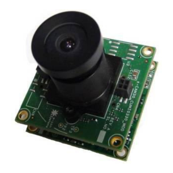
4 Disclaimer The specifications of See3CAM_CU30 camera board and instructions on how to connect this board with PC are provided as reference only and e-con Systems reserves the right to edit/modify this document without any prior intimation of whatsoever. 5 Description The See3CAM_CU30 is a two board solution of size 30mm x 30mm . -
Page 5: Setting Up The See3Cam_Cu30
See3CAM_CU30 Getting Started Manual 03-Feb-2015 their products right away and this helps our customers to cut short the Time-to-Market. This camera board is USB Video Class compatible and this will work with the standard drivers available with Windows and Linux. There is no need for any additional driver installation. Figure 1: See3CAM_CU30 Figure 2: See3CAM_CU30 back to back. -
Page 6: See3Cam_Cu30 To Pc Host Interconnecting Cable
The location of USB3.0 (CN1) connector on See3CAM_CU30 is shown in below figure Figure 4: Location of USB3.0 Connector 6.2.2 Insertion of USB3.0 Cable in Connector The USB3.0 Cable provided by e-con Systems should be inserted with USB3.0 connector as shown in below figure. www.e-consystems.com... -
Page 7: Connecting The Board To Host
See3CAM_CU30 Getting Started Manual 03-Feb-2015 Figure 5: USB3.0 cable inserted in USB3.0 connector 6.2.3 Connecting the board to Host Identify a USB3.0 port. The port which has the below logo is USB3.0 Port. Figure 6: SuperSpeed USB 3.0 Logo The USB3.0 cable needs to be inserted to SuperSpeed USB3.0 port of PC or Laptop. Figure 7: USB3.0 Cable –... - Page 8 See3CAM_CU30 Getting Started Manual 03-Feb-2015 Figure 8: Connecting USB3.0 Cable to Superspeed Port After the insertion of USB3.0 Cable with USB3.0 connector on the board and USB Host, the LED (D1) will glow in Red colour. This indicates that the board is powered ON. Figure 9: Status LED indicating Board Powered ON After selecting the See3CAM_CU30 device in e-CAMView application the D1 LED glows in Green and Red colour.
-
Page 9: Ensuring The Device Connected To Host Properly
See3CAM_CU30 Getting Started Manual 03-Feb-2015 Figure 10: Status LED indicating Camera streaming 6.2.4 Ensuring the device connected to Host properly After the insertion of board to Host, you can confirm that See3CAM_CU30 is properly connected to Host from Imaging Devices. Go to Control Panel ...
Need help?
Do you have a question about the See3CAM CU30 and is the answer not in the manual?
Questions and answers