Lennox SL280UHV Series Unit Information
Hide thumbs
Also See for SL280UHV Series:
- Installation instructions manual (72 pages) ,
- User instruction manual (7 pages) ,
- User's information manual (7 pages)
Table of Contents
Advertisement
S e r v i c e L i t e r a t u r e
LENNOX
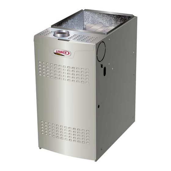
SL280UHV(X) series units are 80% efficiency gas furnac-
es used for upflow or horizontal applications only, man-
ufactured with Lennox Duralok heat exchangers formed
of aluminized steel. SL280UHV(X) units are available in
heating capacities of 66,000 to 132,000 Btuh and cooling
applications up to 5 tons. Refer to Engineering Handbook
for proper sizing.
Units are factory equipped for use with natural gas. Kits
are available for conversion to LPG operation. SL280UH-
V(X) model units are equipped with a communicating
SureLight
two-stage variable speed integrated control.
®
SL280UHV(X) unit meets the California Nitrogen Oxides
(NOx) Standards and California Seasonal Efficiency re-
quirements. All units use a redundant gas valve to assure
safety shut-off as required by C.S.A.
All specifications in this manual are subject to change.
Procedures outlined in this manual are presented as a
recommendation only and do not supersede or replace lo-
cal or state codes. In the absence of local or state codes,
the guidelines and procedures outlined in this manual (ex-
cept where noted) are recommendations only and do not
constitute code.
CAUTION
As with any mechanical equipment, contact with
sharp sheet metal edges can result in personal
injury. Take care while handling this equipment and
wear gloves and protective clothing.
TABLE OF CONTENTS
Specifications . . . . . . . . . . . . . . . . . . . . . . . . . . . . . Page 2
Blower Data . . . . . . . . . . . . . . . . . . . . . . . . . . . . . . Page 3
I Unit Components . . . . . . . . . . . . . . . . . . . . . . . Page 17
II Installation . . . . . . . . . . . . . . . . . . . . . . . . . . . . . Page 47
III Start Up . . . . . . . . . . . . . . . . . . . . . . . . . . . . . . Page 47
VI Maintenance . . . . . . . . . . . . . . . . . . . . . . . . . . Page 52
X Troubleshooting . . . . . . . . . . . . . . . . . . . . . . . . Page 74
UNIT INFORMATION
UNIT INFORMATION
Corp 1116-L4
Revised 05/2022
COMMUNICATING SL280UHNV SERIES UNITS
®
. . . . . . . Page 73
Page 1
WARNING
Improper
installation,
service or maintenance can cause property damage,
personal injury or loss of life. Installation and service
must be performed by a licensed professional HVAC
installer (or equivalent), service agency or the gas
supplier.
WARNING
To prevent serious injury or death:
1- Lock-out/tag-out before performing maintenance.
2- If system power is required (e.g., smoke detector
maintenance), disable power to blower, remove
fan belt where applicable, and ensure all
controllers and thermostats are set to the "OFF"
position before performing maintenance.
3- Always keep hands, hair, clothing, jewelry, tools,
etc., away from moving parts.
SL280UHV
adjustment,
alteration,
©2016 Lennox Industries, Inc.
Advertisement
Table of Contents

Related Manuals for Lennox SL280UHV Series


Summary of Contents for Lennox SL280UHV Series
-
Page 1: Table Of Contents
SL280UHV(X) series units are 80% efficiency gas furnac- es used for upflow or horizontal applications only, man- ufactured with Lennox Duralok heat exchangers formed of aluminized steel. SL280UHV(X) units are available in heating capacities of 66,000 to 132,000 Btuh and cooling applications up to 5 tons. -
Page 2: Specifications
SP ECIF ICATIONS Model No. SL280UH070V36A SL280UH090V36B SL280UH090V48B Heating Model No. - Low Nox SL280UH070XV36A - - - SL280UH090XV48B Performance AFUE High Input - Btuh 66,000 88,000 88,000 Fire Output - Btuh 52,000 70,000 70,000 Temperature rise range - °F 40 - 70 40 - 70 40 - 70... -
Page 3: Blower Data
First stage COOL (two-stage air conditioning units only) is approximately 70% of the same second stage COOL speed position. Continuous Fan Only speed is selectable at 28% and 38% of the selected second stage cooling speed - minimum 250 cfm. Lennox iHarmony Zoning System Applications - Minimum blower speed is 250 cfm. - Page 4 First stage COOL (two-stage air conditioning units only) is approximately 70% of the same second stage COOL speed position. Continuous Fan Only speed is selectable at 28% and 38% of the selected second stage cooling speed - minimum 250 cfm. Lennox iHarmony Zoning System Applications - Minimum blower speed is 250 cfm.
- Page 5 First stage COOL (two-stage air conditioning units only) is approximately 70% of the same second stage COOL speed position. Continuous Fan Only speed is selectable at 28% and 38% of the selected second stage cooling speed - minimum 250 cfm. Lennox iHarmony Zoning System Applications - Minimum blower speed is 250 cfm.
- Page 6 First stage COOL (two-stage air conditioning units only) is approximately 70% of the same second stage COOL speed position. Continuous Fan Only speed is selectable at 28% and 38% of the selected second stage cooling speed - minimum 250 cfm. Lennox iHarmony Zoning System Applications - Minimum blower speed is 250 cfm.
- Page 7 First stage COOL (two-stage air conditioning units only) is approximately 70% of the same second stage COOL speed position. Continuous Fan Only speed is selectable at 28% and 38% of the selected second stage cooling speed - minimum 380 cfm. Lennox iHarmony Zoning System Applications - Minimum blower speed is 380 cfm.
- Page 8 First stage COOL (two-stage air conditioning units only) is approximately 70% of the same second stage COOL speed position. Continuous Fan Only speed is selectable at 28% and 38% of the selected second stage cooling speed - minimum 380 cfm. Lennox iHarmony Zoning System Applications - Minimum blower speed is 380 cfm.
- Page 9 First stage COOL (two-stage air conditioning units only) is approximately 70% of the same second stage COOL speed position. Continuous Fan Only speed is selectable at 28% and 38% of the selected second stage cooling speed - minimum 380 cfm. Lennox iHarmony Zoning System Applications - Minimum blower speed is 380 cfm.
- Page 10 First stage COOL (two-stage air conditioning units only) is approximately 70% of the same second stage COOL speed position. Continuous Fan Only speed is selectable at 28% and 38% of the selected second stage cooling speed - minimum 450 cfm. Lennox iHarmony Zoning System Applications - Minimum blower speed is 450 cfm.
- Page 11 First stage COOL (two-stage air conditioning units only) is approximately 70% of the same second stage COOL speed position. Continuous Fan Only speed is selectable at 28% and 38% of the selected second stage cooling speed - minimum 450 cfm. Lennox iHarmony Zoning System Applications - Minimum blower speed is 450 cfm.
- Page 12 First stage COOL (two-stage air conditioning units only) is approximately 70% of the same second stage COOL speed position. Continuous Fan Only speed is selectable at 28% and 38% of the selected second stage cooling speed - minimum 450 cfm. Lennox iHarmony Zoning System Applications - Minimum blower speed is 450 cfm.
- Page 13 First stage COOL (two-stage air conditioning units only) is approximately 70% of the same second stage COOL speed position. Continuous Fan Only speed is selectable at 28% and 38% of the selected second stage cooling speed - minimum 450 cfm. Lennox iHarmony Zoning System Applications - Minimum blower speed is 450 cfm.
- Page 14 First stage COOL (two-stage air conditioning units only) is approximately 70% of the same second stage COOL speed position. Continuous Fan Only speed is selectable at 28% and 38% of the selected second stage cooling speed - minimum 450 cfm. Lennox iHarmony Zoning System Applications - Minimum blower speed is 450 cfm.
- Page 15 First stage COOL (two-stage air conditioning units only) is approximately 70% of the same second stage COOL speed position. Continuous Fan Only speed is selectable at 28% and 38% of the selected second stage cooling speed - minimum 450 cfm. Lennox iHarmony Zoning System Applications - Minimum blower speed is 450 cfm.
- Page 16 Parts Arrangement HEAT EXCHANGER COMBUSTION AIR INDUCER COMBUSTION AIR INDUCER PRESSURE SWITCH GAS VALVE CABINET BURNER BOX INNER BLOWER PRIMARY LIMIT ACCESS PANEL SIGHT GLASS SECONDARY LIMITS (2 switches) ACCESS PANEL BLOWER ASSEMBLY CONTROL BOX (with blower drive in some units. Not to scale) FIGURE 1 Page 16...
-
Page 17: I Unit Components
I-UNIT COMPONENTS 3. Circuit Breaker (CB8) SL280UHV(X) unit components are shown in FIGURE 1. A 24V circuit breaker is also located in the control box. The gas valve, combustion air inducer and burners can be The switch provides overcurrent protection to the trans- accessed by removing the access panel. - Page 18 Electronic Ignition While in the two-stage thermostat mode (two DIP switch setting) the burners will fire on first-stage heat. The com- At the beginning of the heat cycle the integrated control bustion air inducer will operate on low speed and indoor monitors the first stage and second stage combustion air blower will operate on low heat speed.
- Page 19 IGNITION CONTROL 103130-XX HS/ CAI LINE 1 NEUTRAL 7 SEGMENT LED FLAME SENSE INDOOR BLOWER DIAGNOSTIC CONNECTOR PUSH BUTTON DIP SWITCHES 12 PIN LOW OUTDOOR AIR VOLTAGE SENSOR CONNECTOR TERMINALS DISCHARGE AIR W915 Y1 TO Y2 SENSOR 2 STAGE COMPR TERMINALS W951 R TO O HEAT PUMP...
- Page 20 IGNITION CONTROL 107045-XX RS-BUS LINK (TB82, future use) THERMOSTAT CONNECTIONS (TB1) DS = DEHUMIDIFICATION SIGNAL I+ = DATA HIGH CONNECTION W2 = HEAT DEMAND FROM 2ND STAGE T/STAT I - = DATA LOW CONNECTION R = 24VAC W1 = HEAT DEMAND FROM 1ST STAGE T/STAT I + = DATA HIGH CONNECTION R = CLASS 2 VOLTAGE TO THERMOSTAT I - = DATA LOW CONNECTION...
- Page 21 INTEGRATED CONTROL CONFIGURATION GUIDE CLG BLOWER SPEED ADJUSTMENT 2ND STAGE HEAT ON DELAY DEFAULT 7 MIN CONTINUOUS FAN MODE BLOWER SPEED UPSTAGE THERMOSTAT SELECTION DELAY + 10% MEDIUM−LOW SPEED TWO STAGE (38%) THERMOSTAT 12 MIN UPSTAGE − 10% MEDIUM−HIGH DELAY SPEED 1−STAGE (70%)
- Page 22 Ignition Control Diagnostic Modes Display Action (when button is released) No change (idle)* Remain in idle mode Solid “E” Enter diagnostic recall mode Solid “D” Discharge Air Installed Solid “F” Enter flame signal mode Solid “F” (variable speed only) Program unit capacity size (Unit Code) Two horizontal lines soft disable * No change implies the display will continue to show whatever is currently being displayed for normal operation (blinking...
- Page 23 Ignition Control 103130-XX Diagnostic Codes Code Diagnostic Codes/Status of Equipment Action Required to Clear and Recover Idle mode (Decimal blinks at 1 Hertz -- 0.5 second ON, 0.5 second OFF). Cubic feet per minute (cfm) setting for indoor blower (1 second ON, 0.5 second OFF) / cfm setting for current mode displayed.
- Page 24 Ignition Control 103130-XX Diagnostic Codes Continued Code Diagnostic Codes/Status of Equipment Action Required to Clear and Recover E124 Active communicating thermostat signal Equipment lost communication with the thermostat. Check missing for more than 3 minutes. four wiring connections, ohm wires and cycle power at the thermostat.
- Page 25 Ignition Control 103130-XX Diagnostic Codes Continued Code Diagnostic Codes/Status of Equipment Action Required to Clear and Recover E206 Gas valve second-stage relay failure Furnace will operate on 1st stage for remainder of the heating demand. Will clear after fault recovered. If un- able to operate 2nd stage, replace control.
- Page 26 Ignition Control 103130-XX Diagnostic Codes Continued Code Diagnostic Codes/Status of Equipment Action Required to Clear and Recover E271 Soft lockout - Exceeded maximum number of re- Check pressure (inches w.c.) of low pressure switch clos- tries. Last retry failed due to the pressure switch ing on heat call.
- Page 27 Ignition Control 103130-XX Diagnostic Codes Continued Code Diagnostic Codes/Status of Equipment Action Required to Clear and Recover E312 Restricted air flow in cooling or continu- Warning Only. Restricted airflow - Indoor blower is running at a re- ous fan mode is lower than cfm setting. duced CFM (Cutback Mode - The variable speed motor has pre-set speed and torque limiters to protect the motor from damage caused by operating outside of design parameters (0 to 0.8”...
- Page 28 Ignition Control 103130-XX Diagnostic Codes Continued Code Diagnostic Codes/Status of Equipment Action Required to Clear and Recover E406 LSOM - Compressor open start circuit. Required amount of current is not passing through Start cur- rent transformer. Clears the error after current is sensed in START sensor, or after power reset.
- Page 29 Ignition Control 107045-XX Diagnostic Codes Code Diagnostic Codes/Status of Equipment Action Required to Clear and Recover Idle mode (Decimal blinks at 1 Hertz -- 0.5 second ON, 0.5 second OFF). Cubic feet per minute (cfm) setting for indoor blower (1 second ON, 0.5 second OFF) / cfm setting for current mode displayed.
- Page 30 Ignition Control 107045-XX Diagnostic Codes Continued Code Diagnostic Codes/Status of Equipment Action Required to Clear and Recover E124 Active communicating thermostat signal Equipment lost communication with the thermostat. Check missing for more than 3 minutes. four wiring connections, ohm wires and cycle power at the thermostat.
- Page 31 Ignition Control 107045-XX Diagnostic Codes Continued Code Diagnostic Codes/Status of Equipment Action Required to Clear and Recover E206 Gas valve second-stage relay failure Furnace will operate on 1st stage for remainder of the heating demand. Will clear after fault recovered. If un- able to operate 2nd stage, replace control.
- Page 32 Ignition Control 107045-XX Diagnostic Codes Continued Code Diagnostic Codes/Status of Equipment Action Required to Clear and Recover E271 Soft lockout - Exceeded maximum number of re- Check pressure (inches w.c.) of low pressure switch clos- tries. Last retry failed due to the pressure switch ing on heat call.
- Page 33 Ignition Control 107045-XX Diagnostic Codes Continued Code Diagnostic Codes/Status of Equipment Action Required to Clear and Recover E312 Restricted air flow in cooling or continu- Warning Only. Restricted airflow - Indoor blower is running at a re- ous fan mode is lower than cfm setting. duced CFM (Cutback Mode - The variable speed motor has pre-set speed and torque limiters to protect the motor from damage caused by operating outside of design parameters (0 to 0.8”...
- Page 34 DIP Switch Settings Indoor Blower Operation DIP Switch Settings Switch- es 5 and 6 -- Cooling Mode Blower Speed -- The unit is NOTE - All communicating settings are set at the com- shipped from the factory with the dip switches positioned municating thermostat.
- Page 35 Ramping Option A (Factory Selection) Switches 11, 12 and 13 -- Heating Mode Blower Speed The switches are factory set to the OFF position which • Motor runs at 50% for 30 seconds. provides factory default heat speed. Refer to TABLE 8 for •...
- Page 36 On-Board Link W951 Heat Pump (R to O) On-Board Link W915 2 Stage Compr (Y1 to Y2) On-board link W951 is a clippable connection between On-board link W915 is a clippable connection between terminals R and O on the integrated control. W951 must terminals Y1 and Y2 on the integrated control.
- Page 37 TABLE 11 OPERATING SEQUENCE SL280V, Non-Communicating Thermostat with Humidity Control Feature and Two-Speed Outdoor Unit OPERATING SYSTEM DEMAND SYSTEM RESPONSE SEQUENCE Thermostat Demand Relative Humidity Blower System Compre Step Comments ssor Condition Status (cool) NO CALL FOR DEHUMIDIFICATION Normal Operation Acceptable 70%* Compressor and indoor...
- Page 38 Some units will be equipped with a blower drive shown in FIGURE 8 with LED codes for operation in TABLE 12. The Earlier ECM motors used on other Lennox furnace blower drive is not repairable. If it fails replace the drive.
- Page 39 All SL280UHV blower motors use single phase power. An WARNING external run capacitor is not used. The motor uses perma- nently lubricated ball-type bearings. Disconnect power from unit and wait at Internal Operation least five minutes to allow capacitors to discharge before attempting to service The motor is controlled via serial communication between the integrated control on the furnace and the controller...
- Page 40 BLOWER B3 HARNESS CONNECTORS BLOWER B3 HARNESS CONNECTORS P48 5 Pin P49 4 Pin P48 5 Pin SHAFT SHAFT MOTOR with INTEGRATED CONTROLLER P49 4 Pin MOTOR with INTEGRATED CONTROLLER P48 5 Pin J48 5 Pin P49 4 Pin J49 4 Pin J49 4 Pin Control Connector J48 Connector 120v...
- Page 41 Troubleshooting Motor Windings TEST A Measure the resistance between each of the three motor Ensure that motor windings are not damaged by perform- leads (3-pin plug) and the unpainted part of the end shield. ing the following tests: If the winding resistance to ground is <100k ohms, NOTE - If your ohm meter is not an auto-ranging type, set replace the motor and control module.
- Page 42 The switch is factory set and cannot be adjust- 3. Gas Valve ed. The switch may have a different set point for each unit model number. See Lennox Repair Parts Handbook if limit The valve (FIGURE 19 and FIGURE 20) is internally re- switch must be replaced, dundant to assure safety shut-off.
- Page 43 HEATING COMPONENTS Ignitor Rollout Switch (alternate location) Burner Assembly Rollout Switch Rollout Switch Gas Valve Sensor Burner Box Front Panel Screw (remove and panel will swing open and off) FIGURE 15 Page 43...
- Page 44 Ignitor Check Out Test 1 Remove 5-pin plug from control Check ohms reading across terminals 1and 5 Ohm value should be between 39 - 70. Meter (set to ohms) Integrated control detail Test 2 Seperate the 2-pin jack plug near the manifold and check resistance of the ignitor.
- Page 45 If switch is closed NOTE - Each furnace model uses a unique CAI. Refer to or by-passed, the control will not initiate ignition at start up. Lennox Repair Parts listing for correct inducer for replace- ment. COMBUSTION AIR PRESSURE SWITCH A pressure switch connected to the combustion air induc- er orifice plate is used to prove inducer operation.
- Page 46 Multiple Venting Remove the four mounting screws, rotate the assembly (assembly consists of orifice plate, proving switch, gasket The SL280UHV(X) furnace can vent in multiple positions. and combustion air inducer), then reinstall the mounting See FIGURE 18. screws. See unit Installation Instructions for more detail. The make up box may be removed and the combustion IMPORTANT air inducer may be rotated clockwise or counterclockwise...
-
Page 47: Installation
II-PLACEMENT AND INSTALLATION Make sure unit is installed in accordance with installation Resideo Two-Stage Gs Valve Instructions and applicable codes. HIGH FIRE III-START-UP ADJUSTING SCREW (under cap) A-Preliminary and Seasonal Checks 1 - Inspect electrical wiring, both field and factory installed for loose connections. -
Page 48: Heating System Service Checks
Use of a specialty Gas Leak Detector is strongly recommended. It IMPORTANT is available through Lennox under part number 31B2001. See Corp. 8411-L10, for further details. If a flexible gas connector is required or allowed by... - Page 49 The gas valve is factory set and should not require adjust- TABLE 17 ment. All gas valves are factory regulated. GAS METERING CLOCKING CHART Manifold Adjustment Procedure: Natural 1000 btu/ LP 2500 btu cu/cu ft 1 - Connect test gauge to manifold pressure tap cu ft (FIGURE 19 and FIGURE 20) on gas valve.
- Page 50 TABLE 19 Manifold Pressure Settings Manifold Manifold Manifold Pressure Supply Line Pressure in. Pressure in. wg. in. wg. 7500 - Pressure Orifice Size wg. 4501 - Unit Orifice Size 0 - 4500 ft 7501 - 10,000 ft in. w.g. 7501 - 7500 ft Input 0 - 7500 ft.
-
Page 51: Typical Operating Characteristics
V-TYPICAL OPERATING CHARACTERISTICS C-External Static Pressure A-Blower Operation and Adjustment 1 - Tap locations shown in FIGURE 23. 2 - Punch a 1/4” diameter hole in supply and return air ple- 1 - Blower operation is dependent on thermostat control nums. -
Page 52: Maintenance
2- Check the condition of the belt and shaft bearings if At the beginning of each heating season, and to comply applicable. with the Lennox Limited Warranty, your system should be 3- Inspect all gas pipe and connections for leaks. checked by a licensed professional technician (or equiva-... - Page 53 2 - Verify that system total static pressure and airflow set- 13- To clean the combustion air inducer visually inspect tings are within specific operating parameters. and using a wire brush clean where necessary. Use compressed air to clean off debris and any rust. 3 - Clock gas meter to ensure that the unit is operating at the specified firing rate.
-
Page 54: Wiring And Sequence Of Operation
BURNER, COMBUSTION AIR INDUCER ASSEMBLY & HEAT EXCHANGER REMOVAL Gasket Flue Transition Pressure Switch Heat Exchanger Ignitor Rollout Switches Orifice Plate Collector Box Combustion Air Inducer Flame Sensor Retention Rings Cross Over Manifold And Gas Valve FIGURE 25 Remove 5 screws if necessary VII- Wiring and Sequence of Operation (either side of cabinet) Integrated Control Self Check... - Page 55 Wiring Diagram With Ignition Control 103130-XX Page 55...
- Page 56 Wiring Diagram With Ignition Control 103130-XX and Units With Blower Drive Page 56...
- Page 57 Wiring Diagram With Ignition Control 107045-XX Page 57...
- Page 58 Applications Using a Two-Stage Thermostat 9 - When the combustion air post-purge period is complete, the inducer, the HUM contacts as well A - Heating Sequence -- Integrated Control Thermo- as the 120V ACC terminals are de-energized. The stat Selection DIP Switch 1 OFF in “Two-Stage” Posi- indoor blower is de-energized at the end of the off tion (Factory Setting) delay.
-
Page 59: Field Wiring And Jumper Settings
VIII- Field Wiring With Communicating Enabled Thermostat and DIP Switch Settings Ignition Control 103130-XX Communicating Enabled Furnace and Non- Communicating Enabled Furnace and Communicating Outdoor Unit Communicating Enabled Outdoor Unit COMMUNICATING FURNACE COMMUNICATING FURNACE OPTIONAL DISCHARGE AIR SENSOR OPTIONAL DISCHARGE AIR SENSOR OPTIONAL OUTDOOR... - Page 60 Ignition Control 103130-XX Optional Accessories for use with any Communicating System NOTE: ICOMMUNICATING THERMOSTAT SENSES HUMIDITY & CONTROLS HUM CONTACTS TO CYCLE HUMIDIFIER BASED 120V CONNECTIONS QUIRED. “HUM” CONTACT IS CLOSED ANYTIME HUMIDITY DEMAND IS PRESENT TIONS. BUILT INTO ALL COMMUNICATING ENABLED OUT DOOR UNITS).
- Page 61 LENNOX COMMUNICATING OUTDOOR UNIT INDOOR UNIT (1 OR 2 STAGE) FLOAT SWITCH LENNOX COMMUNICATING OUTDOOR UNIT LENNOX COMMUNICATING FURNACE EL296V, SL280V, SL280VN, SL297V, SLP99V cutting DS to R will not cause communication interuption or error code CUT* R-DS W914 Page 61...
- Page 62 Ignition Control 103130-XX DIP Switch Settings and On-Board Links With a Conventional Thermostat DIP Switch Settings and On-Board Links DIP Switch 1 On Board Links Must Be Cut To Select Thermostat Thermostat Wiring Connections System Options Heating Stages 1 Heat / 1 Cool FURNACE OUTDOOR T'STAT...
- Page 63 Ignition Control 103130-XX DIP Switch Settings and On-Board Links With a Conventional Thermostat DIP Switch Settings and On-Board Links DIP Switch 1 On Board Links Must Be Cut To Select Thermostat Thermostat Wiring Connections System Options Heating Stages 2 Heat / 2 Cool FURNACE OUTDOOR T'STAT...
- Page 64 Ignition Control 103130-XX DIP Switch Settings and On-Board Links With a Conventional Thermostat DIP Switch Settings and On-Board Links DIP Switch 1 Wiring Connections Thermostat On Board Links Must Be Cut To Select Thermostat Heating System Options Stages Dual Fuel FURNACE HEAT PUMP T'STAT...
- Page 65 Ignition Control 103130-XX DIP Switch Settings and On-Board Links With a Conventional Thermostat DIP Switch Settings and On-Board Links DIP Switch 1 Thermostat On Board Links Must Be Cut To Select Wiring Connections Thermostat Heating System Options Stages Dual Fuel FURNACE HEAT PUMP T'STAT...
- Page 66 Ignition Control 107045-XX Communicating Enabled Furnace and Non- Communicating Enabled Furnace and Communicating Outdoor Unit Communicating Enabled Outdoor Unit COMMUNICATING FURNACE COMMUNICATING FURNACE OPTIONAL DISCHARGE AIR SENSOR OPTIONAL DISCHARGE AIR SENSOR OPTIONAL OUTDOOR OPTIONAL COMMUNICATING AIR SENSOR OUTDOOR THERMOSTAT AIR SENSOR COMMUNICATING THERMOSTAT DOOR AIR CONDITIONING...
- Page 67 Ignition Control 107045-XX Optional Accessories for use with Communicating System NOTE: COMMUNICATING THERMOSTAT SENSES HUMIDITY 120V CONNECTIONS & CONTROLS HUM CONTACTS TO CYCLE HUMIDIFIER BASED ON DEMAND. NO OTHER CONTROL OR HUMIDISTAT REQUIRED. “HUM” CONTACT IS CLOSED ANYTIME OPTIONAL OUTDOOR AIR SENSOR FOR USE WITH HUMIDI− HUMIDITY DEMAND FIER (IF NOT ALREADY IN THE SYSTEM FOR OTHER FUNC−...
- Page 68 LENNOX COMMUNICATING OUTDOOR UNIT INDOOR UNIT (1 OR 2 STAGE) FLOAT SWITCH LENNOX COMMUNICATING OUTDOOR UNIT LENNOX COMMUNICATING FURNACE EL296V, SL280V, SL280VN, SL297V, SLP99V cutting DS to R will not cause communication interuption or error code CUT* R−DS W914 FIGURE 2...
- Page 69 Ignition Control 107045-XX DIP Switch Settings and On-Board Links With a Conventional Thermostat DIP Switch Settings and On-Board Links DIP Switch 1 On Board Links Must Be Cut To Select Thermostat Thermostat Wiring Connections System Options Heating Stages 1 Heat / 1 Cool FURNACE OUTDOOR T'STAT...
- Page 70 Ignition Control 107045-XX DIP Switch Settings and On-Board Links With a Conventional Thermostat DIP Switch Settings and On-Board Links DIP Switch 1 On Board Links Must Be Cut To Select Thermostat Thermostat Wiring Connections System Options Heating Stages 2 Heat / 2 Cool FURNACE OUTDOOR T'STAT...
- Page 71 Ignition Control 107045-XX DIP Switch Settings and On-Board Links With a Conventional Thermostat DIP Switch Settings and On-Board Links DIP Switch 1 Thermostat On Board Links Must Be Cut To Select Wiring Connections Thermostat Heating System Options Stages Dual Fuel FURNACE HEAT PUMP L7742U...
- Page 72 Ignition Control 107045-XX DIP Switch Settings and On-Board Links With a Conventional Thermostat DIP Switch Settings and On-Board Links DIP Switch 1 Thermostat On Board Links Must Be Cut To Select Wiring Connections Thermostat Heating System Options Stages Dual Fuel FURNACE HEAT PUMP L7742U...
-
Page 73: Program Unit Capacity Size Mode
IX- Program Unit Capacity Size Mode − − Power-Up - Number displayed represents by integrated control unit size code (furnace model − and capacity). If three horizontal bars are displayed followed by continuous E203, furnace control does not recognize unit size code. Configure per the following: Furnace control in IDLE mode No heating, cooling or indoor fan operation) -
Page 74: Troubleshooting
X- Troubleshooting Heating Sequence of Operation CALL FOR FIRST-STAGE HEAT CALL FOR 1ST STAGE HEAT (LOW FIRE) INDOOR BLOWER OFF AFTER HEAT FAN OFF DELAY (LOW HEAT SPEED) INDOOR LIMIT BLOWER OFF HIGH ERROR SWITCH INDOOR WATCHGUARD − AFTER HEAT FAN LIMIT SWITCH CODE CLOSED WITHIN 3... - Page 75 Heating Sequence of Operation Continued CALL FOR SECOND-STAGE HEAT CALL FOR 2ND STAGE HEAT (HIGH FIRE) SINGLE STAGE 2 STAGE THERMOSTAT THERMOSTAT 2ND STAGE RECOGNITION DELAY ON DELAY (30 SECONDS) EXPIRED? EXPIRED? ONLY FOR 1ST REQUEST FOR 2ND STAGE HEAT INDUCER SWITCHED TO HIGH SPEED HIGH...
- Page 76 Heating Sequence of Operation Continued CALL FOR HEAT SATISFIED FIRST-STAGE HEAT SECOND-STAGE HEAT RUN MODE: 1ST OR 2ND STAGE CALL FOR HEAT. ALL INPUTS MONITORED (LIMIT, PRESSURE, CALL FOR HEAT/COOL, FLAME LEVEL) 2ND STAGE HEAT 2ND STAGE CALL FOR HEAT SATISFIED? DE−ENERGIZE 2ND STAGE GAS VALVE...
- Page 77 Cooling Sequence of Operation CALL FOR COOLING 1ST STAGE COOLING REQUEST RECEIVED WAIT FOR COMPRESSOR TIMED OFF DELAY TO EXPIRE ENERGIZE 1ST STAGE COOLING CONTACTOR (COMPRESSOR & FAN) INDOOR BLOWER 2 SECOND ON DELAY ENERGIZE INDOOR BLOWER (LOW COOLING MODE) MAINTAIN INDOOR BLOWER (LOW COOLING MODE)
- Page 78 Continuous Fan Sequence of Operation CALL FOR FAN CALL FOR FAN INDOOR BLOWER ON CONTINUOUS FAN SPEED MAINTAIN INDOOR CALL FOR FAN BLOWER AT REMOVED? CONTINUOUS FAN REQUEST MAINTAIN INDOOR FOR COOLING GO TO CALL FOR COOLING BLOWER AT RECEIVED? CONTINUOUS FAN REQUEST INDOOR BLOWER OFF...
Need help?
Do you have a question about the SL280UHV Series and is the answer not in the manual?
Questions and answers