Table of Contents
Advertisement
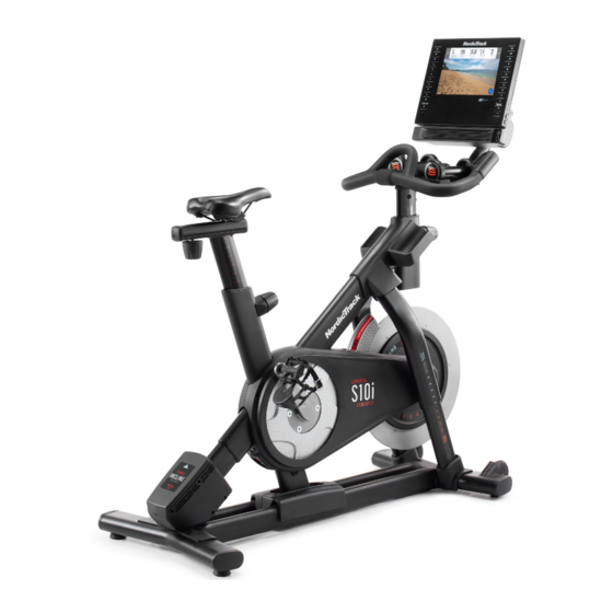
Model No. NTEX03121-INT.1
Serial No.
Write the serial number in the space
above for reference.
Serial Number
CUSTOMER SERVICE
UNITED KINGDOM
Call: 0330 123 1045
From Ireland: 053 92 36102
Website: iconsupport.eu
E-mail: csuk@iconeurope.com
Write:
ICON Health & Fitness, Ltd.
Unit 4, Westgate Court
Silkwood Park
OSSETT
WF5 9TT
UNITED KINGDOM
AUSTRALIA
Call: 1800 993 770
E-mail: australiacc@iconfitness.com
Write:
ICON Health & Fitness, Inc.
PO Box 635
WINSTON HILLS NSW 2153
AUSTRALIA
CAUTION
Read all precautions and
instructions in this manual before
using this equipment. Keep this
manual for future reference.
Decal
USER'S MANUAL
iconeurope.com
Advertisement
Table of Contents

Related Manuals for NordicTrack S10i


Summary of Contents for NordicTrack S10i
- Page 1 Model No. NTEX03121-INT.1 Serial No. USER’S MANUAL Write the serial number in the space above for reference. Serial Number Decal CUSTOMER SERVICE UNITED KINGDOM Call: 0330 123 1045 From Ireland: 053 92 36102 Website: iconsupport.eu E-mail: csuk@iconeurope.com Write: ICON Health & Fitness, Ltd. Unit 4, Westgate Court Silkwood Park OSSETT...
-
Page 2: Table Of Contents
Apply the decal in the location shown. Note: The decal(s) may not be shown at actual size. NORDICTRACK and IFIT are registered trademarks of ICON Health & Fitness, Inc. The Bluetooth ® word mark and logos are registered trademarks of Bluetooth SIG, Inc. and are used under license. Google Maps is a trademark of Google LLC. -
Page 3: Important Precautions
IMPORTANT PRECAUTIONS WARNING: To reduce the risk of serious injury, read all important precautions and instructions in this manual and all warnings on your studio cycle before using your studio cycle. ICON assumes no responsibility for personal injury or property damage sustained by or through the use of this product. -
Page 4: Before You Begin
® COMMERCIAL S10I STUDIO you use the studio cycle. If you have questions after CYCLE. The COMMERCIAL S10I STUDIO CYCLE is reading this manual, please see the front cover of this unlike any ordinary exercise bike. manual. To help us assist you, note the product model number and serial number before contacting us. -
Page 5: Part Identification Chart
PART IDENTIFICATION CHART Use the drawings below to identify the small parts needed for assembly. The number in parentheses below each drawing is the key number of the part, from the PART LIST near the end of this manual. The number following the key number is the quantity needed for assembly. -
Page 6: Assembly
ASSEMBLY • Assembly requires two persons. • In addition to the included tool(s), assembly requires the following tool(s): • Place all parts in a cleared area and remove the one Phillips screwdriver packing materials. Do not dispose of the packing materials until you complete all assembly steps. - Page 7 2. Attach the Front Stabilizer (3) to the Base (2) with four M10 x 20mm Screws (105); do not fully tighten the Screws yet. See the inset drawing. Finish attaching the Front Stabilizer (3) with two additional M10 x 20mm Screws (105). Then, fully tighten all six M10 x 20mm Screws (105).
- Page 8 3. Attach the Rear Stabilizer (4) to the Base (2) with four M10 x 20mm Screws (105); do not fully tighten the Screws yet. See the inset drawing. Finish attaching the Rear Stabilizer (4) with two additional M10 x 20mm Screws (105). Then, fully tighten all six M10 x 20mm Screws (105).
- Page 9 5. Insert the Handlebar (97) into the Handlebar Post (7). Attach the Handlebar with four M8 x 12mm Patch Screws (93); start all the Patch Screws, and then tighten them. 6. Tip: Avoid pinching the wires (C). Slide the Console Support (8) onto the Handlebar (97). Attach the Console Support (8) with an M10 x 55mm Bolt (94) and an M10 Locknut (135);...
- Page 10 7. Look under the Console Support (8) and identify the Upper Wire (123), which has a larger con- nector than the Extension Wire (124). Tip: The wire connectors should slide together easily and snap into place with an audible click. If they do not, turn one connec- tor and try again.
- Page 11 9. IMPORTANT: Have a second person move the Console (10) from side to side, if necessary, so that it is level. While the second person Avoid holds the Console still, firmly tighten the pinching the wires M10 x 55mm Bolt (94). Next, orient the Hand Weight Tray (38) so that the orientation sticker (F) is in the location shown.
- Page 12 11. Note: You can attach your own saddle if desired. See inset drawing a. Tip the Saddle (54) to one side and slide one of the rails (G) as far as possible between the Lower Saddle Clamp (52) and the Upper Saddle Clamp (53). If necessary, further loosen the M8 Saddle Screw (41).
- Page 13 13. Set the two Hand Weights (14) in the Hand Weight Tray (38). IMPORTANT: Make sure not to hit the Console (10) with the Hand Weights (14) when you set the Hand Weights in the Hand Weight Tray (38) after each use. 14.
-
Page 14: How To Use The Studio Cycle
HOW TO USE THE STUDIO CYCLE HOW TO PLUG IN THE POWER ADAPTER Interactive Wireless Touchscreen Console IMPORTANT: If the studio cycle has been exposed The wireless touchscreen console works with iFIT to to cold temperatures, allow it to warm to room tem- provide an interactive and immersive in-home studio perature before you plug in the power adapter (A). - Page 15 How to Adjust the Saddle Carriage How to Adjust the Position of the Console To adjust the The console (F) can position of the be adjusted upward, carriage, loosen downward, or to the carriage knob the side. To adjust (C), move the the position of the carriage forward console, simply...
- Page 16 HOW TO USE THE BRAKE KNOB HOW TO LOCK THE STUDIO CYCLE To change the IMPORTANT: Lock resistance of the the studio cycle pedals, press the when it is not in buttons on the right use. To lock the handlebar (see step studio cycle, press 3 on page 20).
-
Page 17: How To Use The Console
HOW TO USE THE CONSOLE CONSOLE DIAGRAM FEATURES OF THE CONSOLE When you use the manual mode of the console, you can change the resistance of the pedals and the incline The advanced console offers an array of features of the frame with the touch of a button. designed to make your workouts more effective and enjoyable. - Page 18 HOW TO TURN ON THE CONSOLE HOW TO USE THE TOUCH SCREEN The included power adapter must be used to operate The console features a tablet with a full-color touch the studio cycle. See HOW TO PLUG IN THE POWER screen.
- Page 19 HOW TO SET UP THE CONSOLE Firmware updates are always designed to improve your exercise experience. As a result, Before you use the studio cycle for the first time, set up new settings and features may not be described the console. in this manual.
- Page 20 3. Change the resistance of the pedals and the summary will appear on the screen. If desired, you incline of the frame as desired. can publish your results using one of the options on the screen. Then, touch Finish to return to the main Touch Manual Start and begin pedaling.
- Page 21 HOW TO USE A FEATURED WORKOUT When you select a workout, the screen will show an overview of the workout that includes details 1. Touch the screen or press any button on the such as the duration and distance of the workout console to turn on the console.
- Page 22 Note: The calorie goal shown in the workout HOW TO CREATE A DRAW-YOUR-OWN-MAP description is an estimate of the number of WORKOUT calories that you will burn during the workout. The actual number of calories that you burn 1. Touch the screen or press any button on the will depend on various factors, such as your console to turn on the console.
- Page 23 If you make a mistake, touch Undo in the map HOW TO USE AN IFIT WORKOUT options. To use an iFIT workout, you must be logged into your The screen will display the elevation and distance iFIT account (see step 3 below) and the console statistics for your workout.
- Page 24 4. Select an iFIT workout from the home screen or 6. Create a list of favorite iFIT workouts if desired. the workout library. To mark an iFIT workout as a favorite, simply view Touch the buttons at the bottom of the screen to the overview or workout summary of the desired select either the home screen (Home button) or the iFIT workout and touch the favorites button (heart...
- Page 25 HOW TO CHANGE CONSOLE SETTINGS 3. Customize workout settings. IMPORTANT: Firmware updates are always To customize workout settings, touch In Workout, designed to improve your exercise experience. As a and then touch the desired settings. It is result, new settings and features may not be described recommended that you enable the option to show in this manual.
- Page 26 7. Calibrate the incline system. 3. Enable Wi-Fi. To calibrate the incline system, touch Maintenance, Make sure that Wi-Fi ® is enabled. If it is not touch Calibrate Incline, and then touch Begin. The enabled, touch the Wi-Fi toggle to enable it. frame will automatically rise to the maximum incline level, lower to the minimum incline level, and then 4.
- Page 27 HOW TO USE THE SOUND SYSTEM Connect Your Headphones If the console has a headphones jack, you can plug Connect with an Audio Cable your headphones into the headphones jack to listen to If the console has an audio jack, you can connect an audio from the console through your headphones.
-
Page 28: Maintenance And Troubleshooting
MAINTENANCE AND TROUBLESHOOTING MAINTENANCE If the console does not boot up properly, or if the con- Regular maintenance is important for optimal sole freezes and does not performance and to reduce wear. Inspect and properly respond, reset the console tighten all parts each time the studio cycle is used. to the factory default set- Replace any worn parts immediately. - Page 29 HOW TO ADJUST THE LEFT CRANK ARM HOW TO ADJUST THE REED SWITCH If the Left Crank Arm (21) feels loose while you are If the console does not display correct feedback, the pedaling, first loosen the two M6 x 25mm Screws (96). reed switch should be adjusted.
- Page 30 HOW TO ADJUST THE DRIVE BELT If you can feel the pedals slip while you are pedaling, even when the resistance is adjusted to the highest setting, the drive belt may need to be adjusted. To adjust the drive belt, first unplug the power adapter.
-
Page 31: Exercise Guidelines
EXERCISE GUIDELINES Aerobic Exercise—If your goal is to strengthen your WARNING: cardiovascular system, you must perform aerobic Before beginning this exercise, which is activity that requires large amounts or any exercise program, consult your physi- of oxygen for prolonged periods of time. For aerobic cian. -
Page 32: Part List
PART LIST Model No. NTEX03121-INT.1 R0621A Key No. Qty. Description Key No. Qty. Description Frame Resistance Disc Base Lower Saddle Clamp Front Stabilizer Upper Saddle Clamp Rear Stabilizer Saddle M6 Shoulder Screw Anchored Zip Tie Inner Leg Sleeve Pedal Set Handlebar Post #8 x 1/2"... - Page 33 Key No. Qty. Description Key No. Qty. Description Carriage Knob M5 x 8mm Screw – (Not Used) #6 x 5/8" Screw M4 x 10mm Screw Adjustment Block Incline Motor Sleeve M4 x 10mm Blunt Screw M10 x 20mm Screw M10 x 20mm Hex Screw M8 x 83mm Bolt Plastic Spacer M4 x 15mm Machine Screw...
-
Page 34: Exploded Drawing
EXPLODED DRAWING A Model No. NTEX03121-INT.1 R0621A 86 57... - Page 35 EXPLODED DRAWING B Model No. NTEX03121-INT.1 R0621A...
-
Page 36: Ordering Replacement Parts
ORDERING REPLACEMENT PARTS To order replacement parts, please see the front cover of this manual. To help us assist you, be prepared to provide the following information when contacting us: • the model number and serial number of the product (see the front cover of this manual) •...
Need help?
Do you have a question about the S10i and is the answer not in the manual?
Questions and answers
Display distance?
The scream display distance ?
The exact display distance on the NordicTrack S10i is not specified in the provided information. However, the user mentions that the 10" screen provides an immersive and enjoyable experience at the typical viewing distance for this type of exercise bike.
This answer is automatically generated