Table of Contents
Advertisement
Quick Links
Advertisement
Table of Contents

Related Manuals for Dell EMC XC Core XC7525


Summary of Contents for Dell EMC XC Core XC7525
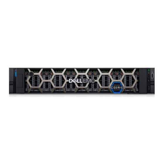
- Page 1 Dell EMC XC Core XC7525 Installation and Service Manual December 2021...
- Page 2 A WARNING indicates a potential for property damage, personal injury, or death. © 2021 - 2021 Dell Inc. or its subsidiaries. All rights reserved. Dell, EMC, and other trademarks are trademarks of Dell Inc. or its subsidiaries. Other trademarks may be trademarks of their respective owners.
-
Page 3: Table Of Contents
Contents Chapter 1: About this document....................7 Chapter 2: System overview......................8 Front view of the system..............................8 Left control panel view............................... 10 Right control panel view..............................11 Rear view of the system..............................12 Inside the system ................................14 Locating the Express Service Code and Service Tag....................15 System information label..............................16 Rail sizing and rack compatibility matrix........................19 Chapter 3: Initial system setup and configuration................20... - Page 4 Removing the left control panel..........................36 Installing the left control panel..........................37 Air shroud.................................... 39 Removing the air shroud............................39 Installing the air shroud..............................39 Removing the GPU air shroud..........................40 Installing the GPU air shroud.............................41 Removing the GPU air shroud top cover.......................42 Installing the GPU air shroud top cover.........................43 Cooling fan..................................
- Page 5 Installing the full length expansion card risers..................... 88 Removing a GPU................................. 90 Installing a GPU................................92 Optional serial COM port..............................95 Removing the serial COM port..........................95 Installing the serial COM port........................... 97 M.2 SSD module................................98 Removing the M.2 SSD module..........................98 Installing the M.2 SSD module..........................
- Page 6 View menu................................... 135 NIC indicator codes.................................136 Power supply unit indicator codes..........................136 Drive indicator codes..............................138 Using system diagnostics.............................. 139 Dell Embedded System Diagnostics........................139 Chapter 8: Getting help......................141 Recycling or End-of-Life service information......................141 Contacting Dell..................................141 Accessing system information by using QRL......................141 Quick Resource Locator for XC Core XC7525 system..................
-
Page 7: Chapter 1: About This Document
About this document This document provides an overview about the system, information about installing and replacing components, technical specifications, diagnostic tools, and guidelines to be followed while installing certain components. About this document... -
Page 8: Chapter 2: System Overview
● Up to 12 x 3.5-inch or 24 x 2.5-inch SAS, SATA, or NVMe drives. NOTE: For more information about how to hot swap NVMe PCIe SSD U.2 device, see the Dell Express Flash NVMe PCIe SSD User's Guide at https://www.dell.com/support... - Page 9 Information tag will also contain the iDRAC secure default password. For more information about the ports, see the www.dell.com/poweredgemanuals section. For more information, see theDell EMC XC Core XC7525 Technical Specifications on the product documentation page. System overview...
-
Page 10: Left Control Panel View
BIOS, and networking parameters. You can also launch the virtual Keyboard, Video, and Mouse (KVM) viewer and virtual Kernel-based Virtual Machine (KVM), on a supported mobile device. For more information, see the Integrated Dell Remote Access Controller User's Guide at www.dell.com/... -
Page 11: Right Control Panel View
Item Indicator or button Icon Description VGA port Enables you to connect a display device to the system. For more information, see the www.dell.com/ poweredgemanuals section. iDRAC Direct port (Micro-AB The iDRAC Direct port (Micro-AB USB) enables you to USB) access the iDRAC Direct Micro-AB features. -
Page 12: Rear View Of The System
Press the power button to gracefully shut down the ACPI-compliant operating system. NOTE: For more information on the ports, see the www.dell.com/poweredgemanuals section. Rear view of the system Figure 6. Rear view of the system Table 5. Rear view of the system... - Page 13 Icon Description VGA port Enables you to connect a display device to the system. For more information, see the www.dell.com/poweredgemanuals section. USB 3.0 port (1) This port is USB 3.0-compliant. iDRAC dedicated port Enables you to remotely access iDRAC. For more information, see the iDRAC User's Guide at www.dell.com/poweredgemanuals...
-
Page 14: Inside The System
Inside the system Figure 7. Inside the system 1. Handle 2. Riser 1 blank 3. Power supply unit (PSU 1) 4. BOSS S2 card slot 5. Riser 2 6. Heat sink for processor 1 7. Memory DIMM socket for processor 1 (E,F,G,H) 8. -
Page 15: Locating The Express Service Code And Service Tag
Figure 8. Inside the system with full length risers 1. Cooling fan cage assembly 2. Cooling fan 3. GPU air shroud 4. GPU air shroud top cover 5. Riser 3 6. Riser 4 7. Handle 8. Riser 1 9. Drive backplane 10. -
Page 16: System Information Label
The Mini Enterprise Service Tag (MEST) label is located on the rear of the system that includes Service Tag (ST), Express Service Code (Exp Svc Code), and Manufacture Date (Mfg. Date). The Exp Svc Code is used by Dell EMC to route support calls to the appropriate personnel. - Page 17 Figure 10. Service information System overview...
- Page 18 Figure 11. Memory information and system board connectors Figure 12. LED behavior, configuration and layout, express service tag for 2.5-inch HDD system System overview...
-
Page 19: Rail Sizing And Rack Compatibility Matrix
Figure 13. LED behavior, configuration and layout, express service tag for 3.5-inch HDD system Rail sizing and rack compatibility matrix For specific information about the rail solutions compatible with your system, see the Dell EMC Enterprise Systems Rail Sizing and Rack Compatibility Matrix available at https://i.dell.com/sites/csdocuments/Business_solutions_engineering-... -
Page 20: Chapter 3: Initial System Setup And Configuration
For more information about setting up the system, see the Getting Started Guide that is shipped with your system. For information on how to manage basic settings and features of the system, see the Dell EMC XC Core XC7525 BIOS and UEFI Reference Guide on the product documentation page. -
Page 21: Options To Set Up Idrac Ip Address
KB article https://www.dell.com/support/article/ sln308699. iDRAC Direct and Quick Sync 2 (optional) Integrated Dell Remote Access Controller User's Guide at https://www.dell.com/idracmanuals or for system specific Integrated Dell Remote Access Controller User's Guide, go to https://www.dell.com/poweredgemanuals... -
Page 22: Options To Log In To Idrac
Ensure that you change the default username and password after setting up the iDRAC IP address. For more information about logging in to the iDRAC and iDRAC licenses, see the latest Integrated Dell Remote Access Controller User's Guide at https://www.dell.com/idracmanuals. -
Page 23: Options To Download And Install Os Drivers
Ensure that you clear the web browser cache before downloading the drivers and firmware. Steps 1. Go to https://www.dell.com/support/drivers. 2. Enter the Service Tag of the system in the Enter a Dell Service Tag, Dell EMC Product ID or Model field, and then press Enter. NOTE: If you do not have the Service Tag, select Detect PC to automatically detect the Service Tag, or click Browse all products, and navigate to your product. -
Page 24: Chapter 4: Installing And Removing System Components
Damage due to servicing that is not authorized by Dell is not covered by your warranty. Read and follow the safety instructions that are shipped with your product. -
Page 25: Before Working Inside Your System
While replacing faulty storage controller, FC, or NIC card with the same type of card, after you power on the system; the new card automatically updates to the same firmware and configuration of the faulty one. For updating to the latest firmware and changing the configuration, see the Lifecycle Controller User's Guide at https://www.dell.com/ idracmanuals. -
Page 26: Cable Routing
Cable routing Figure 14. 12x 3.5-inch Figure 15. 24 x 2.5-inch SAS/SATA hard drives Installing and removing system components... -
Page 27: Rio Card
RIO card Removing the Rear Input Output (RIO) card Prerequisites 1. Follow the safety guidelines listed in the Safety instructions. 2. Follow the procedure listed in Before working inside your system. Remove the system board. Steps 1. Using a Phillips #2 screwdriver, remove the screws that secure the RIO card to the system board. 2. -
Page 28: Optional Front Bezel
Steps 1. Align the connectors and slots on RIO card with the connector and standoffs on the system board. 2. Press the RIO card until firmly seated on the system board connector. 3. Using a Phillips #2 screwdriver, secure the RIO card to the system board with the two screws. Figure 17. -
Page 29: Installing The Front Bezel
Figure 18. Removing the front bezel Next steps Install the front bezel. Installing the front bezel The procedure to install the front bezel with and without the LCD panel is the same. Prerequisites 1. Follow the safety guidelines listed in the Safety instructions. -
Page 30: System Cover
Figure 19. Installing the front bezel System cover Removing the system cover Prerequisites 1. Follow the safety guidelines listed in the Safety instructions. 2. Power off the system, and any attached peripherals. 3. Disconnect the system from the electrical outlet and peripherals. Steps 1. -
Page 31: Installing The System Cover
Figure 20. Removing the system cover Next steps Install the system cover. Installing the system cover Prerequisites 1. Follow the safety guidelines listed in the Safety instructions. 2. Follow the procedure listed in Before working inside your system. 3. Ensure that all internal cables are connected and routed properly, and no tools or extra parts are left inside the system. Steps 1. -
Page 32: Drive Backplane Cover
Figure 21. Installing the system cover Next steps 1. Follow the procedure listed in After working inside your system. Drive backplane cover Removing the drive backplane cover Prerequisites 1. Follow the safety guidelines listed in the Safety instructions. 2. Follow the procedure listed in Before working inside your system. -
Page 33: Installing The Drive Backplane Cover
Figure 22. Removing the drive backplane cover Next steps Install the drive backplane cover. Installing the drive backplane cover Prerequisites 1. Follow the safety guidelines listed in the Safety instructions. Steps 1. Align the drive backplane cover with the guide slots on the system. 2. -
Page 34: Control Panel
Figure 23. Installing the drive backplane cover Next steps 1. Follow the procedure listed in After working inside your system. Control panel Removing the right control panel Prerequisites 1. Follow the safety guidelines listed in the Safety instructions. 2. Follow the procedure listed in Before working inside your system. -
Page 35: Installing The Right Control Panel
Figure 24. Removing the right control panel Next steps Install the right control panel. Installing the right control panel Prerequisites 1. Follow the safety guidelines listed in the Safety instructions. 2. Follow the procedure listed in Before working inside your system. -
Page 36: Removing The Left Control Panel
NOTE: The numbers on the image do not depict the exact steps. The numbers are for representation of sequence. Figure 25. Installing the right control panel Next steps Install the side wall bracket. Install the cooling fan assembly. Install the drive backplane cover. -
Page 37: Installing The Left Control Panel
Steps 1. Disconnect the control panel cable from the connector on the system board. 2. Using the Phillips #1 screwdriver, remove the screws that secure the left control panel and the left control panels cable cover to the system. 3. Hold the left control panel cable, and slide the left control panel out of the system. NOTE: Observe the routing of the cable as you remove the right control panel from the system. - Page 38 4. Using the Phillips #1 screwdriver, tighten the screws to secure the left control panel and the left control panel cable cover to the system. NOTE: The numbers on the image do not depict the exact steps. The numbers are for representation of sequence. Figure 27.
-
Page 39: Air Shroud
Air shroud Removing the air shroud Prerequisites CAUTION: Never operate your system with the air shroud removed. The system may get overheated quickly, resulting in shutdown of the system and loss of data. 1. Follow the safety guidelines listed in the Safety instructions. -
Page 40: Removing The Gpu Air Shroud
2. Lower the air shroud into the system until it is firmly seated. Figure 29. Installing the air shroud Next steps 1. Follow the procedure listed in After working inside your system. Removing the GPU air shroud Prerequisites CAUTION: Never operate your system with the air shroud removed. The system may get overheated quickly, resulting in shutdown of the system and loss of data. -
Page 41: Installing The Gpu Air Shroud
Figure 30. Removing the GPU air shroud Next steps Install the air shroud. Installing the GPU air shroud Prerequisites 1. Follow the safety guidelines listed in the Safety instructions. 2. Follow the procedure listed in Before working inside your system. Steps 1. -
Page 42: Removing The Gpu Air Shroud Top Cover
Figure 31. Installing the GPU air shroud Next steps 1. Follow the procedure listed in After working inside your system. Removing the GPU air shroud top cover Prerequisites CAUTION: Never operate your system with the air shroud removed. The system may get overheated quickly, resulting in shutdown of the system and loss of data. -
Page 43: Installing The Gpu Air Shroud Top Cover
Figure 32. Removing the GPU air shroud top cover Next steps Install the GPU air shroud top cover. Installing the GPU air shroud top cover Prerequisites 1. Follow the safety guidelines listed in the Safety instructions. 2. Follow the procedure listed in Before working inside your system. -
Page 44: Cooling Fan
Figure 33. Installing the GPU air shroud top cover Next steps 1. Follow the procedure listed in After working inside your system. Cooling fan Removing the cooling fan cage assembly Prerequisites 1. Follow the safety guidelines listed in the Safety instructions. -
Page 45: Installing The Cooling Fan Cage Assembly
Figure 34. Removing the cooling fan cage assembly Next steps Install the cooling fan assembly. Installing the cooling fan cage assembly Prerequisites 1. Follow the safety guidelines listed in the Safety instructions. CAUTION: Ensure that the cables inside the system are correctly installed and retained by the cable retention bracket before installing the cooling fan cage assembly. -
Page 46: Removing A Cooling Fan
Figure 35. Installing the cooling fan cage assembly Next steps 1. If removed, Install the air shroud. 2. Follow the procedure listed in After working inside your system. Removing a cooling fan Prerequisites 1. Follow the safety guidelines listed in the Safety instructions. -
Page 47: Installing A Cooling Fan
Figure 36. Removing a cooling fan Next steps Install a cooling fan. Installing a cooling fan Prerequisites 1. Follow the safety guidelines listed in the Safety instructions. 2. Follow the procedure listed in Before working inside your system. Steps Align and slide the cooling fan into the cooling fan assembly until the fan clicks into place. NOTE: The procedure to install standard, high-performance (silver grade), or high-performance (gold grade) fan is same. -
Page 48: Side Wall Brackets
Figure 37. Installing a cooling fan Next steps 1. If removed, Install the air shroud. 2. Follow the procedure listed in After working inside your system. Side wall brackets Removing the side wall bracket Prerequisites 1. Follow the safety guidelines listed in the Safety instructions. -
Page 49: Installing The Side Wall Bracket
Figure 38. Removing the side wall bracket Next steps Install the side wall bracket. Installing the side wall bracket Prerequisites 1. Follow the safety guidelines listed in the Safety instructions. 2. Follow the procedure listed in the Before working inside your system. -
Page 50: Drives
Figure 39. Installing the side wall bracket Next steps Install the cooling fan assembly. 2. If removed, Install the air shroud. Install the drive backplane cover. 4. If installed, Install the front bezel. 5. Follow the procedure listed in the After working inside your system. -
Page 51: Installing A Drive Blank
Figure 40. Removing a drive blank Next steps Install the drive blank. Installing a drive blank Prerequisites 1. Follow the safety guidelines listed in the Safety instructions. 2. If installed, Remove the front bezel. Steps Insert the drive blank into the drive slot until the release button clicks into place. Figure 41. -
Page 52: Installing The Drive Carrier
CAUTION: Before attempting to remove or install a drive while the system is running, see the documentation for the storage controller card to ensure that the host adapter is configured correctly to support drive removal and insertion. CAUTION: To prevent data loss, ensure that your operating system supports drive installation. For more information about the drives installation or uninstallation requirements, see the operating system's user guide. -
Page 53: Removing The Drive From The Drive Carrier
NOTE: Ensure that the drive carrier's release handle is in the open position before inserting the carrier into the slot. 1. Follow the safety guidelines listed in the Safety instructions. 2. If installed, Remove the front bezel. 3. Remove the drive carrier or remove the drive blank when you want to assemble the drives in to the system. Steps 1. -
Page 54: Installing The Drive Into The Drive Carrier
2. Lift the drive out of the drive carrier. Figure 44. Removing the drive from the drive carrier Next steps Install the drive into the drive carrier. Installing the drive into the drive carrier Prerequisites 1. Follow the safety guidelines listed in the Safety instructions. -
Page 55: Drive Backplane
Figure 45. Installing a drive into the drive carrier Next steps Install the drive carrier. 2. If removed, Install the front bezel. Drive backplane Drive backplane Depending on your system configuration, the drive backplanes supported are listed here: Table 9. Supported backplane options System Supported hard drives options XC Core XC7525... - Page 56 Figure 46. 8 x 2.5-inch drive backplane 1. BP_PWR_CTRL 2. BP_DST_SA1 (PERC to backplane) 3. DST_PA1 (PCIe/NVMe connector) 4. DST_PB1 (PCIe/NVMe connector) 5. DST_PA2 (PCIe/NVMe connector) 6. BP_PWR_1 (backplane power and signal cable to system board) 7. DST_PB2 (PCIe/NVMe connector) Figure 47.
-
Page 57: Removing The Drive Backplane
Figure 49. 24 X 2.5-inch drive backplane 1. DST_SA1 2. SRC_SA1 3. DST_SB1 4. BP_PWR_1 5. DST_PA1 (PCIe/NVMe connector) 6. BP_PWR_2 7. DST_PB1 (PCIe/NVMe connector) 8. BP_PWR_CTRL 9. DST_PA2 (PCIe/NVMe connector) 10. DST_PB2 (PCIe/NVMe connector) Removing the drive backplane Prerequisites CAUTION: To prevent damage to the drives and backplane, remove the drives from the system before removing the backplane. -
Page 58: Installing The Drive Backplane
Figure 50. Removing the drive backplane Next steps Install the drive backplane. Installing the drive backplane Prerequisites 1. Follow the safety guidelines listed in the Safety instructions. 2. Follow the procedure listed in the Before working inside your system. Remove the drive backplane cover. -
Page 59: Front Perc Module
Figure 51. Installing the drive backplane Next steps Install the cooling fan cage assembly. Install all drives. 3. If removed, Install the air shroud. Install the drive backplane cover. 5. Connect the drive backplane cables to the connector on the system board. 6. -
Page 60: Installing The Front Mounting Front Perc Module
Figure 52. Removing the front mounting front PERC module Next steps Install the front mounting front PERC module. Installing the front mounting front PERC module Prerequisites 1. Follow the safety guidelines listed in the Safety instructions. 2. Follow the procedure listed in Before working inside your system. -
Page 61: Removing The Rear Mounting Front Perc Module
Figure 53. Installing the front mounting front PERC module Next steps 1. Reconnect all the required cables. 2. If removed, Install the air shroud. Install the drive backplane cover. 4. Follow the procedure listed in After working inside your system. Removing the rear mounting front PERC module Prerequisites 1. -
Page 62: Installing The Rear Mounting Front Perc Module
Figure 54. Removing the rear mounting front PERC module Next steps Install the rear mounting front PERC module. Installing the rear mounting front PERC module Prerequisites 1. Follow the safety guidelines listed in the Safety instructions. 2. Follow the procedure listed in Before working inside your system. -
Page 63: System Memory
Figure 55. Installing the rear mounting front PERC module Next steps Install the drive backplane. 2. If removed, Install the air shroud. Install the drive backplane cover. 4. Follow the procedure listed in After working inside your system. System memory System memory guidelines The XC Core XC7525 system supports DDR4 registered DIMMs (RDIMMs) and Load Reduced DIMM (LRDIMMs). - Page 64 Figure 56. Memory channels Memory channels are organized as follows: Table 10. Memory channels Processor Channel Channel Channel C Channel D Channel E Channel F Channel G Channel H Processor 1 Slots A6 Slots A5 Slots A2 Slots A1 and Slots A8 and Slots A7 Slots A4 and...
-
Page 65: General Memory Module Installation Guidelines
NOTE: The older 32 GB capacity RDIMM memory with x4 data width and 8Gb DRAM density cannot be mixed with the newer 32GB capacity RDIMM memory with x8 data width and 16Gb DRAM density in the same AMD EPYC™ processor unit. NOTE: The older 128GB capacity LRDIMM memory at 2666 MT/s speed cannot be mixed with the new 128GB capacity LRDIMM memory at 3200 MT/s speed. - Page 66 ● The BIOS Setup menu presents the applicable NPSx options based on the underlying model number. A change to the current NPSx is communicated to pre-BIOS firmware to take effect on the next boot. The default NPS setting is 1. ●...
-
Page 67: Removing A Memory Module
● BIOS default NPS setting is 1. ● UEFI0391 message may be displayed during boot if DIMMs are configured in the blank spaces of the table. ● If the processor does not support the desired NPS setting for a given number of DIMMs, then use default setting (NPS1) and the UEFI0391 message is displayed. -
Page 68: Installing A Memory Module
Figure 57. Removing a memory module Next steps Install the memory modules. Installing a memory module Prerequisites 1. Follow the safety guidelines listed in the Safety instructions. 2. Follow the procedure listed in Before working inside your system. 3. If installed, Remove the air shroud. -
Page 69: Processor And Heat Sink
Figure 58. Installing a memory module Next steps 1. If removed, Install the air shroud. 2. Follow the procedure listed in After working inside your system. 3. To verify if the memory module has been installed properly, press F2 and navigate to System Setup Main Menu > System BIOS >... -
Page 70: Removing The Processor
d. Loosen the captive screws 3 and 4 completely. NOTE: The captive screw numbers are marked on the heat sink. 2. Lift the heat sink from the system. Figure 59. Removing a heat sink Next steps 1. If you are uninstalling a faulty heat sink, Install the heat sink, else Remove the... - Page 71 Figure 60. Removing screws on the force plate 2. Release the processor socket rail frame by lifting the blue latches. Figure 61. Lifting the rail frame 3. Holding the blue tab on the processor tray, slide the tray out of the rail frame. Installing and removing system components...
-
Page 72: Installing The Processor
Figure 62. Removing the processor tray Next steps Install the processor. Installing the processor Prerequisites 1. Follow the safety guidelines listed in the Safety instructions. 2. Follow the procedure listed in Before working inside your system. Remove the heat sink. Steps 1. - Page 73 Figure 63. Placing the processor tray into the rail frame 2. Push the rail frame down until the blue latches lock into place. Figure 64. Closing the rail frame 3. Secure the force plate to the processor socket base by tightening the screws in the sequence 1, 2, and 3. When all three screws are fully threaded, the socket is then actuated.
-
Page 74: Installing The Heat Sink
Figure 65. Securing the force plate Next steps Install the heat sink. 2. Follow the procedure listed in After working inside your system. Installing the heat sink Prerequisites Never uninstall the heat sink from a processor unless you intend to replace the processor or system board. The heat sink is necessary to maintain proper thermal conditions. - Page 75 Figure 66. Applying thermal grease CAUTION: Applying too much thermal grease can result in excess grease coming in contact with and contaminating the processor socket. NOTE: The thermal grease syringe is intended for single use only. Dispose of the syringe after you use it. 3.
-
Page 76: Expansion Cards And Expansion Card Risers
A system event entry is logged in the iDRAC Lifecycle Controller if an expansion card riser is not supported or missing. It does not prevent your system from turning on. However, if a F1/F2 pause occurs with an error message, see Troubleshooting expansion cards section in the Dell EMC PowerEdge Servers Troubleshooting Guide at https:// www.dell.com/poweredgemanuals. - Page 77 Internal Mellanox (OCP: 25 Gb) Internal Intel (OCP: 10 Gb) Internal Broadcom (OCP: 10 Gb) Internal Intel (OCP: 10 Gb) Internal Dell BOSS S2 Adapter (Low Profile) Internal Dell BOSS Adapter (Low Profile) 3, 6 Installing and removing system components...
-
Page 78: Removing The Expansion Card Risers
Removing the expansion card risers Prerequisites 1. Follow the safety guidelines listed in the Safety instructions. 2. Follow the procedure listed in Before working inside your system. 3. Disconnect any cables that are connected to the expansion card. Steps 1. For Riser 1, loosen the captive screws on the riser. a. - Page 79 Figure 69. Removing the expansion card riser (Riser 2) 3. For Riser 3, loosen the captive screw, and then press the blue release tab and holding the edges lift the expansion card riser from the riser connector on the system board. Figure 70.
-
Page 80: Installing The Expansion Card Risers
Figure 71. Removing the expansion card riser (Riser 4) Next steps Install the expansion card riser. Installing the expansion card risers Prerequisites 1. Follow the safety guidelines listed in the Safety instructions. 2. Follow the procedure listed in Before working inside your system. - Page 81 Figure 72. Installing the expansion card riser (Riser 1) Figure 73. Installing the expansion card riser (Riser 2) Installing and removing system components...
- Page 82 Figure 74. Installing the expansion card riser (Riser 3) Figure 75. Installing the expansion card riser (Riser 4) Installing and removing system components...
-
Page 83: Removing Expansion Card From The Expansion Card Riser
Next steps 1. If required, re-connect the cables to the expansion card. 2. Follow the procedure listed in After working inside your system. 3. Install any device drivers required for the card as described in the documentation for the card. Removing expansion card from the expansion card riser Prerequisites 1. -
Page 84: Installing An Expansion Card Into The Expansion Card Riser
Figure 77. Installing the filler bracket Next steps 1. If applicable, Install an expansion card into an expansion card riser. Installing an expansion card into the expansion card riser Prerequisites 1. Follow the safety guidelines listed in the Safety instructions. 2. -
Page 85: Removing The Full Length Expansion Card Risers
Figure 78. Removing the filler bracket 3. Hold the card by its edges, and align the card edge connector with the expansion card connector on the riser. 4. Insert the card edge connector firmly into the expansion card connector until the card is fully seated. 5. - Page 86 2. Follow the procedure listed in Before working inside your system. Remove the GPU air shroud top cover. Steps 1. To remove expansion card Riser 1A: a. Loosen the captive screws on the riser. b. Press the blue release tab and holding the edges lift the expansion card riser from the riser connector on the system board.
- Page 87 Figure 81. Removing the expansion card riser (Riser 3A) 3. To remove expansion card Riser 4A: a. Disconnect the GPU power cable from the system board. b. Loosen the captive screw. c. Press the blue release tab and holding the edges lift the expansion card riser from the riser connector on the system board.
-
Page 88: Installing The Full Length Expansion Card Risers
Next steps Install the full length expansion card riser. Installing the full length expansion card risers Prerequisites 1. Follow the safety guidelines listed in the Safety instructions. 2. Follow the procedure listed in Before working inside your system. 3. If removed, Install the GPU into the expansion card riser. - Page 89 Figure 84. Installing the expansion card riser (Riser 3A) 2. To install the full length expansion card Riser 4A: a. Holding the edges or the touch points, align the holes on the expansion card riser with the guides on the system board. b.
-
Page 90: Removing A Gpu
Next steps 1. If removed, Install the GPU air shroud. Install the GPU air shroud top cover. 3. Follow the procedure listed in After working inside your system. 4. Install any device drivers required for the card as described in the documentation for the card. Removing a GPU Prerequisites 1. - Page 91 2. To remove the GPU from Riser 3 and 4: a. Slide the expansion card latch on the riser. b. Disconnect the GPU power cable from the GPU card. c. Press the button, and pull the black card holder before removing the GPU card from the riser. d.
-
Page 92: Installing A Gpu
Figure 88. Installing the metal filler bracket Next steps Install the GPU. Installing a GPU Prerequisites WARNING: Consumer-Grade GPU should not be installed or used in the Enterprise Server products. 1. Follow the safety guidelines listed in the Safety instructions. 2. - Page 93 Figure 89. Removing the metal filler bracket 2. To install the GPU on Riser 1: a. Align the connector on the GPU with the connector on the riser. b. Insert the GPU into the riser until it is fully seated. c.
- Page 94 Figure 90. Installing GPU on Riser 1 3. To install the GPU on Riser 3 and 4: a. Align the connector on the GPU with the connector on the riser. b. Insert the GPU into the riser until it is fully seated. c.
-
Page 95: Optional Serial Com Port
Figure 91. Installing GPU on Riser 3 and Riser 4 Next steps 1. If removed, Install the GPU air shroud. Install the GPU air shroud top cover. Install the full length expansion card riser. 4. Follow the procedure listed in After working inside your system. - Page 96 Figure 92. Removing the Serial COM port 2. Disconnect the serial COM port cable from the serial port. Figure 93. Removing the Serial COM port Next steps Install the serial COM port. Installing and removing system components...
-
Page 97: Installing The Serial Com Port
Installing the serial COM port Prerequisites 1. Follow the safety guidelines listed in the Safety instructions. 2. Follow the procedure listed in Before working inside your system. Remove the expansion card riser. 4. Disconnect the serial COM port cable from the connector on the rear I/O board. Steps 1. -
Page 98: M.2 Ssd Module
Figure 95. Installing the Serial COM port Next steps 1. Reconnect the serial COM port cable to the connector on the rear I/O board. Install the expansion card riser. 3. Follow the procedure listed in After working inside your system. M.2 SSD module Removing the M.2 SSD module Prerequisites... -
Page 99: Installing The M.2 Ssd Module
Figure 96. Removing the M.2 SSD module Next steps Install the M.2 SSD module. Installing the M.2 SSD module Prerequisites 1. Follow the safety guidelines listed in the Safety instructions. 2. Follow the procedure listed in Before working inside your system. -
Page 100: Boss S2 Card (Optional)
Figure 97. Installing the M.2 SSD module Next steps 1. Install the BOSS card. Installing the BOSS is similar to Install the expansion card into the expansion card riser. 2. Follow the procedure listed in After working inside your system. BOSS S2 card (optional) Removing the BOSS card filler Prerequisites... -
Page 101: Installing The Boss Card Filler
Figure 98. Removing the BOSS card filler Next steps Install the BOSS card filler Install the BOSS S2 controller card module. Installing the BOSS card filler Prerequisites 1. Follow the safety guidelines listed in the Safety instructions. Steps Align the BOSS card filler with the BOSS S2 controller card module bay and push it into the bay until it clicks into place. Figure 99. -
Page 102: Removing The Boss S2 Controller Card Module
Removing the BOSS S2 controller card module Prerequisites 1. Follow the safety guidelines listed in the Safety instructions. 2. Follow the procedure listed in the Before working inside your system. Steps 1. Pull and lift the BOSS S2 card carrier retention latch lock to open. 2. -
Page 103: Installing The Boss S2 Controller Card Module
Figure 102. Removing the BOSS S2 controller card module 7. Remove the BOSS power cable and BOSS signal cable from the BOSS S2 controller card module. Figure 103. Removing the BOSS power cable and BOSS signal cable from the BOSS S2 controller card module Next steps Remove the BOSS S2 controller card module Install the BOss card filler... - Page 104 Steps 1. Connect the BOSS power cable and BOSS signal cable to the BOSS S2 controller card module. Figure 104. Connecting the BOSS power cable and BOSS signal cable to the BOSS S2 controller card module 2. Align the BOSS S2 controller card module at an angle with the controller card module slot. 3.
-
Page 105: System Battery
Figure 106. Installing the M.2 SSD 9. Slide the BOSS S2 card carrier into the BOSS S2 controller card module slot. 10. Close the BOSS S2 card carrier release latch to lock the carrier in place. Figure 107. Installing the BOSS S2 card carrier Next steps 1. - Page 106 according to the manufacturer's instructions. See the Safety instructions. that came with your system for more information. 1. Follow the safety guidelines listed in the Safety instructions. 2. Follow the procedure listed in Before working inside your system. 3. If applicable, disconnect the power or data cables from the expansion cards. Remove the expansion card risers.
-
Page 107: Intrusion Switch Module
Figure 109. Removing the system battery Next steps Install the expansion card risers. 2. If applicable, connect the cables to one or more expansion cards. 3. Follow the procedure listed in After working inside your system. 4. Confirm that the battery is operating properly, by performing the following steps: a. -
Page 108: Installing The Intrusion Switch Module
Figure 110. Removing the intrusion switch module Next steps Install the intrusion switch module. Installing the intrusion switch module Prerequisites 1. Follow the safety guidelines listed in the Safety instructions. 2. Follow the procedure listed in Before working inside your system. -
Page 109: Optional Ocp Card
Figure 111. Installing the intrusion switch module Next steps Install the expansion card riser. 2. Follow the procedure listed in After working inside your system. Optional OCP card Removing the OCP card Prerequisites 1. Follow the safety guidelines listed in the Safety instructions. - Page 110 Figure 112. Removing the OCP card 4. If the OCP card is not going to be replaced, install a filler bracket . Figure 113. Installation of filler bracket Next steps Install the OCP card. Installing and removing system components...
-
Page 111: Installing The Ocp Card
Installing the OCP card Prerequisites 1. Follow the safety guidelines listed in the Safety instructions. 2. Follow the procedure listed in Before working inside your system. Remove the expansion card riser. Steps 1. If installed, remove the filler bracket. Figure 114. Removal of filler bracket 2. -
Page 112: Power Supply Unit
While replacing the hot swappable PSU, after next server boot; the new PSU automatically updates to the same firmware and configuration of the replaced one. For more information about the Part replacement configuration, see the Lifecycle Controller User's Guide at https://www.dell.com/idracmanuals. Hot spare feature Your system supports the hot spare feature that significantly reduces the power overhead associated with power supply unit (PSU) redundancy. -
Page 113: Removing A Power Supply Unit Blank
4. Unlatch and lift or remove the optional cable management accessory if it interferes with the PSU removal. For information about the cable management when the PSU is removed or installed while the system is in a rack, see the system’s cable management arm documentation at https://www.dell.com/poweredgemanuals. Steps Press the release latch, and holding the PSU handle slide the PSU out of the PSU bay. -
Page 114: Installing A Power Supply Unit
Figure 116. Removing a power supply unit Next steps Install the PSU Install the PSU blank. Installing a power supply unit Prerequisites 1. Follow the safety guidelines listed in the Safety instructions. 2. For systems that support redundant PSU, ensure that both the PSUs are of the same type and have the same maximum output power. -
Page 115: Trusted Platform Module
PSU is removed or installed while the system is in the rack, see the system’s cable management accessory documentation at https://www.dell.com/poweredgemanuals. 2. Connect the power cable to the PSU, and plug the cable into a power outlet. -
Page 116: Initializing Tpm For Users
2. Press to hold the module down and remove the screw using the security Torx 8-bit shipped with the TPM module. 3. Slide the TPM module out from its connector. 4. Push the plastic rivet away from the TPM connector and rotate it 90° counterclockwise to release it from the system board. 5. -
Page 117: System Board
System board Removing the system board Prerequisites CAUTION: If you are using the Trusted Platform Module (TPM) with an encryption key, you may be prompted to create a recovery key during program or System Setup. Be sure to create and safely store this recovery key. If you replace this system board, you must supply the recovery key when you restart your system or program before you can access the encrypted data on your drives. -
Page 118: Installing The System Board
Next steps Install the system board. Installing the system board Prerequisites NOTE: Before replacing the system board, replace the old iDRAC MAC address label in the Information tag with the iDRAC MAC address label of the replacement system board 1. Follow the safety guidelines listed in the Safety instructions. -
Page 119: Restoring Service Tag Using Easy Restore
4. If you are not using Easy restore, import your new or existing iDRAC Enterprise license. For more information, see the Integrated Dell Remote Access Controller User's Guide available at https://www.dell.com/idracmanuals. 5. Follow the procedure listed in After working inside your system. -
Page 120: Lom Card And Rear I/O Board
NOTE: You can enter the Service Tag only when the Service Tag field is empty. Ensure that you enter the correct Service Tag. After the Service Tag is entered, it cannot be updated or changed. 5. Click OK. LOM card and rear I/O board Removing the LOM card and rear I/O board Prerequisites 1. - Page 121 Steps 1. Align the connectors and slots on the LOM card or rear I/O board with the connector and standoffs on the system board. 2. Press the LOM card or rear I/O board until firmly seated on the system board connector. 3.
-
Page 122: Chapter 5: Upgrade Kits
Upgrade Kits The table lists the available After Point Of Sale [APOS] kits. Table 16. Upgrade kits Kits Related links to service instructions GPU kit Hard drives Installing the drive carrier Hard drives SSD Installing the drive into the drive carrier Memory Installing a mempory module Network cards (Standard PCIe adapter... -
Page 123: Gpu Kit
High performance (silver grade) fan or high performance (gold grade) cooling fans. See the cooling fan and foam requirement matrix for the cooling fan and foam requirement for different configurations. You can see www.dell.com/poweredgemanuals topic to identify the fans types. Upgrade Kits... - Page 124 Table 18. Cooling fan and foam requirement matrix System configuration Cooling fan Foam requirement No backplane High performance (silver grade) fan Not required 8 x 2.5-inch NVMe High performance (silver grade) fan Not required 16 x 2.5-inch SAS/SATA High performance (silver grade) fan Not required 16 x 2.5-inch SAS/SATA + 8 NVMe High-performance (gold grade) fan...
- Page 125 Table 20. GPU power cable matrix (continued) Category Description Type Vendor Cable Cable quantity CRD,GRPHC,32GB,2 FH and FL NVIDIA 8 pin cable 1 piece per GPU riser 50W,V100S,PCIE CRD,GRPHC,NVIDIA, FH and FL NVIDIA 8 pin cable 1 piece per GPU riser 24GB,RTX6000 CRD,GRPHC,NVIDIA, FH and FL...
- Page 126 Figure 123. Installing Mylar foam on the system cover After installing, follow the After working inside your system instructions. Upgrade Kits...
-
Page 127: Chapter 6: Jumpers And Connectors
Jumpers and connectors This section provides essential and specific information about jumpers and switches. It also describes the connectors on the various boards in the system. Jumpers on the system board help to disable the system and reset the passwords. To install components and cables correctly, you must be able to identify the connectors on the system board. - Page 128 Table 21. System board jumpers and connectors (continued) Item Connector Description SL6_CPU2_PB4 PCIe/NVMe connector 6 IO_RISER3 (CPU2) Riser 3 SIG_PWR_3 GPU power J_R3_PCIE_PWR Riser 3 power connector Rear I/O connector Rear I/O connector Coin cell battery Coin cell battery Riser 2 IO_RISER2_A (CPU1) IO_RISER2_B (CPU2) OCP NIC 3.0 connector...
-
Page 129: System Board Jumper Settings
Damage due to servicing that is not authorized by Dell is not covered by your warranty. Read and follow the safety instructions that are shipped with your product. - Page 130 NOTE: If you assign a new system and/or setup password with the jumper on pins 4 and 6, the system disables the new password(s) the next time it boots. 5. Reconnect the system and all the attached peripherals. 6. Power off the system. 7.
-
Page 131: Chapter 7: System Diagnostics And Indicator Codes
System diagnostics and indicator codes This section describes the diagnostic indicators on the system front panel display system status during system startup. Topics: • Status LED indicators • System health and system ID indicator codes • iDRAC Quick Sync 2 indicator codes •... -
Page 132: System Health And System Id Indicator Codes
For information about the event and error messages generated by the system firmware and agents that monitor system components, go qrl.dell.com > Look Up > Error Code, type the error code, and then click Look it... -
Page 133: Idrac Quick Sync 2 Indicator Codes
If the problem persists, see the Getting help section, https://www.dell.com/poweredgemanuals or Dell OpenManage Server Administrator User’s Guide at https://www.dell.com/openmanagemanuals. Solid amber Indicates that the system is in fail-safe Restart the system. If the problem persists, see mode. -
Page 134: Lcd Panel
The LCD panel is used to configure or view the iDRAC IP address of the system. For information about the event and error messages generated by the system firmware and agents that monitor system components, go to qrl.dell.com >... -
Page 135: Setup Menu
For information about the event and error messages generated by the system firmware and agents that monitor system components, go to qrl.dell.com > Look Up > Error Code, type the error code, and then click Look it up.. -
Page 136: Nic Indicator Codes
NIC indicator codes Each NIC on the back of the system has indicators that provide information about the activity and link status. The activity LED indicator indicates if data is flowing through the NIC, and the link LED indicator indicates the speed of the connected network. Figure 128. - Page 137 Table 31. AC PSU status indicator codes Power indicator codes Condition Green Indicates that a valid power source is connected to the PSU and the PSU is operational. Blinking amber Indicates an issue with the PSU. Not powered on Indicates that the power is not connected to the PSU. Blinking green Indicates that the firmware of the PSU is being updated.
-
Page 138: Drive Indicator Codes
Table 32. DC PSU status indicator codes (continued) Power indicator codes Condition CAUTION: If two PSUs are used, they must be of the same type and have the same maximum output power. CAUTION: When correcting a PSU mismatch, replace the PSU with the blinking indicator. Swapping the PSU to make a matched pair can result in an error condition and an unexpected system shutdown. -
Page 139: Using System Diagnostics
Using system diagnostics If you experience an issue with the system, run the system diagnostics before contacting Dell for technical assistance. The purpose of running system diagnostics is to test the system hardware without using additional equipment or risking data loss. - Page 140 Table 34. System diagnostic controls (continued) Menu Description Event log Displays a time-stamped log of the results of all tests run on the system. This is displayed if at least one event description is recorded. System diagnostics and indicator codes...
-
Page 141: Chapter 8: Getting Help
Dell contact information on your purchase invoice, packing slip, bill or Dell product catalog. The availability of services varies depending on the country and product, and some services may not be available in your area. To contact Dell for sales, technical... -
Page 142: Quick Resource Locator For Xc Core Xc7525 System
Dell EMC. This information is used by Dell EMC Technical Support to troubleshoot the issue. ● Proactive contact — A Dell EMC Technical Support agent contacts you about the support case and helps you resolve the issue. -
Page 143: Chapter 9: Documentation Resources
This section provides information about the documentation resources for your system. To view the document that is listed in the documentation resources table: ● From the Dell EMC support site: 1. Click the documentation link that is provided in the Location column in the table. - Page 144 Methods to download firmware and drivers section in this document. Managing your system For information about systems management https://www.dell.com/poweredgemanuals software offered by Dell, see the Dell OpenManage Systems Management Overview Guide. For information about setting up, using, https://www.dell.com/openmanagemanuals >...