
Related Manuals for Psion 8585


Summary of Contents for Psion 8585
- Page 1 8585 / 8595 VEHICLE-MOUNT COMPUTERS User Manual ® (Windows XP Embedded or Professional) July 28, 2011 Part No. 8000240.A ISO 9001 Certified Quality Management System...
- Page 2 This document and the information it contains is the property of Psion Inc. This document is not to be used, reproduced or copied, in whole or in part, except for the sole purpose of assisting in proper use of Psion manufactured goods and services by their rightful owners and users.
- Page 3 Return-To-Factory Warranty Psion Inc. provides a return to factory warranty on this product for a period of twelve (12) months in accor- dance with the Statement of Limited Warranty and Limitation of Liability provided at: www.psion.com/warranty The warranty on Psion manufactured equipment does not extend to any product that has been tampered with, altered, or repaired by any person other than an employee of an authorized Psion service organiza- tion.
-
Page 5: Table Of Contents
Overview of the 8585 and 8595 Vehicle-Mount Computers ....... . . - Page 6 Configuration with Psion Config Program........
- Page 7 Approvals ......................62 Appendix A: Psion Config Program Basic Safety Guidelines.
- Page 8 Information on 8585 ........
- Page 9 Table of Contents A.14.2.1 Current Configuration ............... . . A-24 A.14.2.2 Exceptions for Write Protection .
- Page 11 About the 8585 / 8595 Vehicle-Mount Computer User Manual ......4...
-
Page 13: Chapter 1: Introduction
In this manual, Psion Inc. strives to provide all the information required for using your 8585. However, because this is a versatile product that can be used in many different scenarios, we cannot guarantee that the information contained in this manual will cover every single aspect. -
Page 14: Packaging
Psion Inc. will not assume responsibility for any damage caused by the improper use of the 8585 or 8595 and/or disregard of the instructions in this manual. -
Page 15: Text Conventions
Chapter 7: Maintenance and Troubleshooting describes the care of the 8585, steps to investigate problems, and common usage mistakes. Chapter 8: Device Description and Technical Specifications lists the specifications for the 8585 and 8595 computers. - Page 17 2.11 8585 Declaration of Conformity........
-
Page 18: Always Install, Operate, And Maintain The Unit Properly
Supply of Fresh Air: Avoid overheating the unit The 8585 is based on a passive cooling concept. As a result, the waste heat which is produced inside the device is emitted over the surface of the housing. For this system to function properly, sufficient fresh air circulation is required. -
Page 19: Power Supply
The power supply cables must be laid in accordance with the applicable local installation regulations. Ensure that no persons are injured in case the mounting bracket breaks The 8585 may in no case be installed in such a way that persons can be injured during a breaking of the mounting bracket (e.g. fatigue break). -
Page 20: External Devices
Never carry out repairs on the device yourself. Always contact Psion's technical support and send in your unit for repair if necessary. On the back of the 8585 you will find the device's type plate which has important information about the device which you must quote for technical service. It provides important information about the configura- tion and manufacture of the device in abbreviated form. -
Page 21: Rtte Directive 1999/5/Ec
[Swedish]: 1999/5/EC. 2.9.1 Special Rule/Restriction For the 8585 with WLAN 802.11a/b/g/n, the following restrictions apply: • WLAN 5 GHz band: 5.15 GHz – 5.35 GHz may only be used indoors. • WLAN operation outdoors in France is only permitted in the 2454 – 2483.5 MHz range at max. -
Page 22: Transmission Of Radio Frequencies
The 8585 can affect the function of medically implanted devices such as pacemakers and create interfer- ence. Do not place the 8585 near such devices. Keep a minimum distance of 20 cm between such a device and the 8585 in order to reduce the risk of interference. -
Page 23: 8585 Declaration Of Conformity
Mike Doyle Guy-Franck Nakach Full Name Full Name Vice President, Engineering Vice Président, Worldwide Channel Sales Position Position PSION Inc. Canada PSION UK Ltd., UK Place Place June 2, 2011 June 2, 2011 Date Date Psion 8585/8595 Vehicle-Mount Computers User Manual... -
Page 24: 8595 Declaration Of Conformity
Mike Doyle Guy-Franck Nakach Full Name Full Name Vice President, Engineering Vice Président, Worldwide Channel Sales Position Position PSION Inc. Canada PSION UK Ltd., UK Place Place June 2, 2011 June 2, 2011 Date Date Psion 8585/8595 Vehicle-Mount Computers User Manual... - Page 25 3.2 Psion Config: Front Keys, WLAN, Automatic Switch-off ....... . .
-
Page 27: Chapter 3: Basic Operation
Removing the Protective Film from the Display The front display of the 8585 is protected during transport by a transparent film. This film should remain on the front display during assembly to avoid damage to the front display surface. -
Page 28: Wlan Settings
Psion Antenna Solutions for Use in Germany The integrated Psion antenna solutions are based on the prevailing IEEE 802.11 standard. This standard allows wireless data transfer at rates from 1 Mbps to 54 Mbps using the 2.4 GHz and 5 GHz frequency band (300 Mbps if using IEEE 802.11n). -
Page 29: Summit Client Utility For Wlan Configuration
Configuring the antenna transmitting power with SCU (example) 3.3.3 Summit Client Utility for WLAN Configuration The Summit Client Utility (called “SCU” below) is used to set up the WLAN configuration for the 8585. Warning: WLAN configurations may only be modified by qualified IT technical staff. -
Page 30: Password Scu
Password SCU Depending on the configuration, it may be necessary to enter a password. Figure 3.5 Summit Client Utility menu To do so, click the Admin Login button. An input field appears for the password. Psion 8585/8595 Vehicle-Mount Computers User Manual... -
Page 31: Protecting The Tft Display From The Memory Effect
Protecting the TFT Display from the Memory Effect The TFT display of the 8585 has to be protected from the burning in of a motionless image. An image that has remained motionless for too long can cause irreversible damage to the display. With TFT displays there no cathode rays burning in an afterimage as in old TV sets or monitors, but TFT displays still have a “memory effect”. -
Page 32: Connectors
(PN 13985–301) is available as an accessory. The power extension cable is connected to the vehicle on one side and the adaptor cable on the other side. All cables can be used with every voltage. Psion offers an ‘ig- nition’ and a ‘screen blanking’ (display-off) adaptor cable. The external wire of the adapter cable must be connected to the ground lug of the terminal and to the vehicle chassis. -
Page 33: Dc Voltage Supply Connector
‘Ignition on’ means that a control signal has to be routed to this connection (e.g., ignition of a vehicle), that matches the supply voltage level and is able to supply at least 1 W to the 8585. The signal reference is DC–. -
Page 34: Connecting External Devices
Make sure that external peripheral devices with their own power supply are switched on at the Property same time as the 8585 or after you start the 8585. If this is not possible, please ensure that Damage the 8585 is adequately protected from power leakage caused by an external device. - Page 35 4.6.1.1 Wiring Vehicle Power to the 8585/8595 ....... 28 4.6.2 Position of the 8585 in the Vehicle ........29 4.6.3 Overview of the Assembly Steps .
-
Page 37: Chapter 4: Installing The Computer
Pay careful attention to Chapter 2: “Approvals and Basic Safety Guidelines”. Mechanical Dynamic Loading Since the 8585 is a weighted structure, it is invariable that the unit will be subject to mechanical dynamic effects. Therefore optimizing the mounting is necessary. -
Page 38: Vehicle Applications (Such As Forklifts)
• If you want to connect devices fed by other power sources to the 8585, such as printers and so on, be sure to power up the peripheral devices at the same time or after the 8585. Otherwise, you may encounter start-up problems, malfunctions or even irreparable damage to the device. -
Page 39: Position Of The 8585 In The Vehicle
A 1.8 meter (6 ft.) extension power cable (PN 13985–301) is available which should be used to wire the 8585/8595 to the truck battery. This cable needs to be ordered separately. This cable should be wired to a filtered, fused (maximum 10A) accessory supply on the vehicle. On negative chassis vehicles, the positive lead should be fused. -
Page 40: Cable Cover (Splash Guard)
8585. Damage Protection class In order to comply with the certified protection class, please use the assembly kit included with the 8585. Please observe the installation instructions included with this assembly kit. Strain Relief After the 8585 and bracket are fastened: •... - Page 41 The antenna cap/service USB interface may only remain open for the duration of the service work. It may only be opened and closed by qualified technical personnel. No objects or fluids may be introduced into the 8585 while the antenna cap and the USB interface are open.
- Page 43 5.6.5.2 Automatic Switch-off Process........40 5.6.5.3 Configuration with Psion Config Program ....... 40...
-
Page 45: Chapter 5: Operation
Chapter 5: Operation Touchscreen Touchscreen The 8585 is equipped with a resistive touchscreen. Caution: Keep the panel surface clean. Property Prevent any kind of adhesive from being applied to the surface. Damage Avoid high voltage and/or static charge. Touchscreens may not be operated with ball-point pens or writing utensils, tools of any kind (e.g. -
Page 46: Calibration
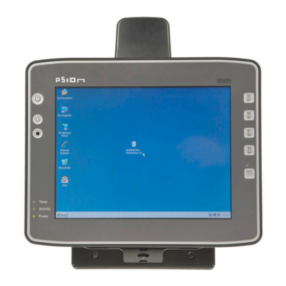
The 8585 has the following front keys and LEDs: Figure 5.2 8585 front keys and LEDs Power key Special keys Manual brightness control Shift key LEDs 5.2.1 Power Key If you want to start the 8585 using the [Power] key: Psion 8585/8595 Vehicle-Mount Computers User Manual... -
Page 47: Manual Brightness Control
5.2.4 Special Keys Special keys [S1] to [S8] The special keys can be configured with the Psion Config program (select the Front keys menu). 5.2.5 Shift Key Switch the keys [S1], [S2], [S3] and [S4] to [S5], [S6], [S7] and [S8]. -
Page 48: Operating System
Installing on Flash When an 8585 is started up for the first time without a pre-installed operating system, the user needs to carry out a number of steps that will vary depending on the system to be installed. Refer to the relevant op- erating system manual for specific instructions. -
Page 49: Tips And Tricks
5.6.4 Network Adaptor (10/100/1000) The 8585 is equipped with a 10/100 Mbit network adaptor. This adaptor features an RJ45 port. The network controller undertakes the entire task of connecting the hardware to the network. The RJ45 connection port features two integrated status LEDs. They display the following messages: Figure 5.3... -
Page 50: Problems With Data Transmission Via Lan/Ethernet
The Psion Config program must be installed for the automatic switch-off module to function correctly. If the Psion Config has not been started, the 8585 will carry out a hard shutdown once the delay time and shutdown time set by the hardware (e.g. via MPCCOM.EXE) has elapsed. In this case, the operating system is not shut down normally before the power is switched off. - Page 51 To ensure that vital data is always saved correctly, applications need to be able to properly respond to the WM_QUERYENDSESSION message, that is, without user queries and within the set time period. Further information on the Psion Config program can be found in Appendix A: “Psion Config Program”. Psion 8585/8595 Vehicle-Mount Computers User Manual...
- Page 53 6.7 WLAN Card (PCIe MiniCard) ..........46 Psion 8585/8595 Vehicle-Mount Computers User Manual...
-
Page 55: Chapter 6: Accessories
SMALL keyboard 6.1.2 24-key Keypad A 24-key keypad which can be mounted onto the 8585 is available, with a protection class IP 65. Figure 6.2 24-key keypad Scanner Bracket Scanner brackets are available for the 8585 for current scanners (optional). Scanner brackets can be fas- tened to the left or right of the unit. -
Page 56: Usb Recovery Stick
Chapter 6: Accessories USB Recovery Stick USB Recovery Stick With the optional Psion recovery stick, images can be backed up and restored on the 8585 if necessary (backup and recovery). Please consult your Psion sales representative if necessary. Scanners You can connect scanners to either the USB port or the serial port. If connected to COM1, the scanner can be powered through the port (optional, 5 V). - Page 57 7.4 Disposal ............. . 50 Psion 8585/8595 Vehicle-Mount Computers User Manual...
-
Page 59: Chapter 7: Maintenance And Troubleshooting
Observe correct voltage ranges. 7.3.2 Powering Up/Down • Please note that the function of the 8585's [Power] key varies depending on how the device is configured. • Only disconnect the computer from the power supply after the computer has been properly shut down and switched off. -
Page 60: Mobile Application On Vehicles
Use neutral detergent or isopropyl alcohol on a clean soft cloth to clean the panel surface. • Prevent using any kind of chemical solvent, acidic or alkali solution. Disposal The Psion general terms and conditions set out the obligations for disposal in accordance with official elec- tronics regulations. Psion 8585/8595 Vehicle-Mount Computers User Manual... - Page 61 8.6 Dimensions 8585/10 ........
-
Page 63: Chapter 8: Device Description And Technical Specifications
• The 8585 with 10.4" display. • The 8595 with 12.1" display. Abbreviations Used for Devices and Accessories Please note that to save space on the 8585 and supplied accessories, the following abbreviations have been used: Table 8.1 Abbreviation Meaning... -
Page 64: Device/Type Identification
Chapter 8: Device Description and Technical Specifications Device/Type identification Device/Type identification 8.4.1 Device Type Plate The device type plate on the 8585 contains the following information: Table 8.2 8585 Describes the vehicle-mount computer with a 10" display Describes the vehicle-mount computer with a 12" display... -
Page 65: Motherboard
2 x USB 2.0 host Properties: • USB 2.0 HiSpeed • Fused at 0.5 A per channel • Fused for ESD level 4 (compliant with EN 61000-4-2). For example for mouse, keyboard, USB stick. Psion 8585/8595 Vehicle-Mount Computers User Manual... -
Page 66: Lcd Interface
Ethernet Realtek RTL8111 10/100/1000 MB/s Drivers available for: • MS-DOS 6.2x • MS Windows XP Professional • MS Windows XP Embedded and Linux Network Connection RJ45 plug-in connector Integrated transmitter Two integrated status LEDs Psion 8585/8595 Vehicle-Mount Computers User Manual... -
Page 67: Power Supply
Power Consumption Standby: typically 1 W (8585/10 with DC power pack in standby mode) * The SELV circuit is a secondary circuit that is designed and protected so that its voltages will not exceed a safe value both when operating correctly or if a single error occurs. -
Page 68: Ambient Conditions
5 hrs. noise 3.6 g effective and 36 vibrations with 30 g peaks Shock-Resistance US Highway Truck according to MIL-STD 810 G: 2000 (Department of Defense), 3 hrs. noise 1 g effective and 600 vibrations 20 g peaks in operation Psion 8585/8595 Vehicle-Mount Computers User Manual... -
Page 69: Dimensions 8585/10
Chapter 8: Device Description and Technical Specifications Dimensions 8585/10 Dimensions 8585/10 8.6.1 Front View Dimensions without add-ons (in mm). Figure 8.2 Dimensions 8585 front view Psion 8585/8595 Vehicle-Mount Computers User Manual... -
Page 70: Side View
Chapter 8: Device Description and Technical Specifications Side View 8.6.2 Side View Dimensions without add-ons (in mm). Figure 8.3 Dimensions 8585 side view Psion 8585/8595 Vehicle-Mount Computers User Manual... -
Page 71: Top View
Chapter 8: Device Description and Technical Specifications Top View 8.6.3 Top View Dimensions without add-ons (in mm). Figure 8.4 Dimensions 8585 top view Psion 8585/8595 Vehicle-Mount Computers User Manual... -
Page 72: Vesa Drill Holes
VESA Drill Holes 8.6.4 VESA Drill Holes The VESA drill holes on the 8585 are visible on this diagram. Dimensions without add-ons (in mm). Figure 8.5 Position of the VESA drill holes Approvals Please see “8585 Declaration of Conformity” on page 13 and “8595 Declaration of Conformity” on page 14 for the list of regulatory approvals. - Page 73 A.3.2 Pre-installed on Psion Computers ........
-
Page 74: Appendix A: Psion Config Program
A.15.2 Info Header of an Export File..........29 Psion 8585/8595 Vehicle-Mount Computers User Manual... -
Page 75: Basic Safety Guidelines
Damage qualified technical personnel, e.g. persons qualified in computer/network/system administration may perform Psion Config settings. If improper changes of the Psion Config settings are performed by the customer, this releases Psion from all liability for warranty claims. Overview of Functions Note: The Psion Config software automatically recognizes the 8585 type and the installed operat- ing system. -
Page 76: Installation
A.3.4 Automatic Installation of Software Keyboard Psion software keyboard is automatically installed as part of the Psion Config installation. If no license is available for this software, the keyboard will only function for three minutes. It then stops working. For further information about the software keyboard, please refer to the instruction manual of the same name. -
Page 77: Starting The Program
Only ASCII files can be loaded at this time. UNICODE is not supported. Loading language files Text files for Psion Config are loaded when the program is started. If a text file is not available in the desired language, the system default text (in English) is used for the dialogs. -
Page 78: Hardware Monitor
Appendix A: Psion Config Program Hardware Monitor Hardware Monitor In the Hardware Monitor menu, 8585 system information is displayed: • 8585 serial number • Psion model • Installed processor • Firmware version • BIOS version • Inside temperature of the 8585 Figure A.3 8585 Hardware monitor menu... -
Page 79: Environment
Appendix A: Psion Config Program Environment Environment The environment controller in the 8585 features monitoring and statistics functions. The Environment menu provides information on the measured values. A.5.1 Information on 8585 Figure A.4 8585 Environment menu Table A.2 Environment controller... -
Page 80: Automatic Switch-Off Configuration Dialog
Damage the 8585 connected to a car ignition. The automatic shutdown settings for 8585 devices that are not going to be installed into a vehicle must also be correctly set for the device type! Figure A.5 Automatic Switch-off menu on 8585 Don't forget to save these settings with the Save button. -
Page 81: Settings
Red: The computer is in shutdown or switch-off mode. Unable to read power status. Double-click or right-click with the mouse to open a popup menu where Psion Config can be started. A small dialog is displayed in the foreground where a counter counts down the after- Show counter if ignition is off run time until shutdown. -
Page 82: Switch-On
The 8585 can be switched on with the power key. The 8585 switches on as soon as it is supplied with power. It is not necessary to press always on the power key or start the ignition. -
Page 83: Configuration Dialog
Appendix A: Psion Config Program Configuration Dialog A.7.1 Configuration Dialog Figure A.6 8585 Front Panel Keyboard menu A.7.2 Assigning Front Panel Keys Select the key to be changed, it appears in the Current assignment field. Press the Change key button. The Define key input dialog appears. -
Page 84: Common System Settings
A CFG file and hence a particular keyboard layout can be specified for the Keyboard definition for the logon logon (it may differ from the default keyboard). Changes to this setting are activated only after the computer has been restarted. Psion 8585/8595 Vehicle-Mount Computers User Manual... -
Page 85: Common
The CFG file for the software keyboard is specified, e.g. “C:\Psion\Keyboard.cfg” A.8.1.5 Keyboard / Front Key Locking Parameter Description Using this setting, all keyboard inputs/key inputs on the 8585 can be locked. • Front panel buttons Lock keyboard and front keys • External keyboard • Software keyboard (via touch screen) Locking is only active after restarting the computer. -
Page 86: Common
A.8.2.4 Keyboard / Front Key Locking Parameter Description Using this setting, all keyboard inputs/key inputs on the 8585 can be locked. • Front panel buttons Lock keyboard and front keys • External keyboard • Software keyboard (via touch screen) Locking is only active after restarting the computer. -
Page 87: Network Settings
Find information about settings for the network adapter currently selected in the Current Settings window. The System Settings button opens the Windows dialog for networks. Figure A.8 Network Settings: Common menu A.9.1.1 Computer name The 8585 host name can be changed. A.9.1.2 Network Adapter Parameter Description... -
Page 88: Network Startup
Network Startup You can define programs in this menu which should be started after a network connection is successfully established with a server (after every boot of the operating system). Figure A.10 Network Startup Psion 8585/8595 Vehicle-Mount Computers User Manual... -
Page 89: Autostart Programs
Then start programs without The programs can also be started without a network connection. network Info text in waiting dialog The text entered here will be displayed on the waiting dialog. Psion 8585/8595 Vehicle-Mount Computers User Manual... -
Page 90: Wlan
Appendix A: Psion Config Program WLAN A.11 WLAN In this menu, you can configure whether a WLAN status window will be displayed on the 8585, with infor- mation about signal strength and quality of the WLAN connection. A.11.1 Information on the WLAN Status Window Figure A.11 WLAN Status Window... -
Page 91: Basic Legend For Signal Strength
The background color of the WLAN status window is selected. Click the color Set background color field to see a palette of all available colors. Psion 8585/8595 Vehicle-Mount Computers User Manual... -
Page 92: Connect Program
“Debug_Logging=0”entry is located by default in section CfgWLANStatus 0 means: no log file will be generated. 1 means: a log file will be generated and written to the Psion directory. Filename of the log file: WLAN_DebugLog.txt. Restart the computer to activate the setting and generate the log file. -
Page 93: Information In The Wlan Log File
Otherwise system errors are a threat, since if the EWF is deactivated storage media will be filled with log files (size of a WLAN log file: up to 50 MB. When this size is reached, the Psion Config automatically creates BAK files, which are sequentially numbered.) Figure A.13 Example of a WLAN log file... -
Page 94: Software Activation
In the Software activation menu, options such as automatic switch-off and software keyboard can be acti- vated. If these options are purchased at a later date (after the 8585 delivery), customers receive an activa- tion key or a license file, which must be entered here. -
Page 95: Enhanced Write Filter
Take over changes the system. Once finished, write protection is immediately active again. • Click Set Command to apply the settings. • Click the Exec. Restart button to restart the computer and activate the settings. Psion 8585/8595 Vehicle-Mount Computers User Manual... -
Page 96: File Based Write Filter
Memory size available for the overlays. Entries between 64 and 1024 MB are pos- Maximum size of the cache sible. Pre-allocation of complete cache Maximum memory is not dynamic, but statically reserved in advance. memory Psion 8585/8595 Vehicle-Mount Computers User Manual... -
Page 97: Exceptions For Write Protection
When FBWF is active, files are shown here that are protected by FBWF and that were changed during the run time. The following is possible here: • apply changes and write them to the file system Psion 8585/8595 Vehicle-Mount Computers User Manual... - Page 98 With OK the file is skipped, the procedure Write changes to data media is carried out for the Explanation: next file on the list. With Cancel, the procedure Write changes to data media is interrupted. Psion 8585/8595 Vehicle-Mount Computers User Manual...
-
Page 99: Settings
With Cancel, the procedure Write changes to data media is interrupted. A.15 Settings In this menu, Psion Config is configured with respect to password, language etc. Figure A.21 Settings menu Psion 8585/8595 Vehicle-Mount Computers User Manual... - Page 100 Psion Config sitive. Allow read access without password: Psion Config can be started without a password. It is possible to read all data, but no Reading all data changes may be made to the settings. Limited to data without COM A password is not required to start Psion Config.
-
Page 101: Command Lines Parameter Import (Only For Administrators
A.15.1 Command Lines Parameter IMPORT (only for administrators) The parameter IMPORT is available for import using batch job (Psion Config V 2.3 and higher). Example: PsionCfg IMPORT=<Path>AnyExportedData.cfg The CFG file to be imported must be generated using export from Psion Config. -
Page 103: Index
50 dynamic loading 27 battery, vehicle 9 BIOS 55 brightness control 37 electrical installation 28 emergency shutdown 9 error messages, Psion Config program A-26 cable ignition adaptor 22 screen blanking adaptor 22 FBWF supply 22 advice A-5 cable cover 30, 49... - Page 104 Germany, antenna regulations 18 supply 9, 27, 49, 57 ground, logic and shield 28 fuses 57 ground bolt 28 protection 9 safety 9 powering up/down the 8585 24 programs, Autostart A-17 housing 54 Protection Class 8, 30 humidity 58 protective antenna cap 30...
- Page 105 Signal Strength, Psion Config program A-19 settings 18 signal strength and quality A-18 status display 17 software compatibility 55 Status Window / Radio Card, Psion Config program Software Keyboard A-20 activate A-22 status Windows settings dialog, Psion Config program logon A-12...
Need help?
Do you have a question about the 8585 and is the answer not in the manual?
Questions and answers