
Related Manuals for Samsung MCM-D211UN


Summary of Contents for Samsung MCM-D211UN
- Page 1 Air conditioner Installation manual MCM-D211UN • Thank you for purchasing this Samsung air conditioner. • Before operating this unit, please read this installation manual carefully and retain it for future reference.
- Page 2 Contents ..................
-
Page 3: Safety Information
Safety Information When installing the product, the following safety precautions must be taken for the safety of an installer and user. Use R-410A refrigerant. reliability of the product. Safety precautions must be taken when installing the refrigerant pipe. When charging mixed refrigerant, you should use liquid refrigerant (If you charge gaseous refrigerant, it may affect the capacity and reliability of the product as a result of change in formation of the refrigerant.) FOR INSTALLATION... - Page 4 Safety Information FOR INSTALLATION CAUTION Proper earthing should be done as per the rating. Do not connect the ground wire to the gas pipe, water pipe, lightning rod or a ground wire of a telephone. If the grounding is incomplete, electric shock may occur. Follow the instructions in this manual to make sure that the condensed water dripping from the drain hose runs out properly and insulate the drain pipe so that dew condensation is not generated.
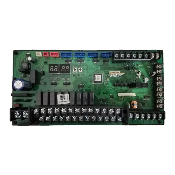
- Page 5 Name of each part and product dimension Name of each part and product dimension Control assembly (Control part) (Unit : inch(mm)) Place for Universal Comm. Kit Wire saddle 13.78"(350mm) 15.16"(385mm) Wire clamp EEV Assembly (Electronic Expansion Valve): Accessory (Ordered separately) For detailed information of EEV installation, refer to the installation manual of EEV Assembly which you need to purchase additionally.
-
Page 6: Accessories Supplied
Parts Accessories (supplied) Discharge air Inlet sensor holder temperature sensor Name Room temperature sensor 32.8’(10m) 32.8’(10m) Quantity Shape Name Aluminum tape Rubber tape Insulator Cable tie Quantity Shape It is not mandatory to connect discharge air temperature sensor. Additional accessory (not included) * Wired remote controller * Wired remote controller * Simple Wired remote... - Page 7 Checking before using a Universal Comm. Kit Structure diagram of a Universal Comm. Kit Outdoor unit EEV Control Liquid valve Communication cable: Exhaust Outdoor Return air Supply air IN sensor * Room Temperature Gas pipe Wired remote controller OUT sensor...
- Page 8 Installing a Universal Comm. Kit Installing Control assembly 1. Check the installation location of Control assembly. You can choose either indoor unit attachment type or indoor unit separation type depending on the installation environment. Make sure that the Control assembly is not exposed to sunlight by covering with a case which has Wire holder Functions of Control assembly communication with an indoor unit or wired remote controller.
- Page 9 (COM) COOL HEAT AUTO COM TEMP COM ENTHALPY EXT-CTRL COMP/ERROR EEV1 EEV2 EEV3 EEV4 AC 24V DEFROST DEFROST ON DEFROST OFF COOL_T COOL THERMO ON COOL THERMO OFF THERMO THERMO ON THERMO OFF FREE COOL_IN FREE COOL ON FREE COOL OFF INPUT INPUT LEVEL OUT...
- Page 10 Installing a Universal Comm. Kit Simple BMS Simple BMS setting Installation option. Discharge temperature can be set by DMS. controller usage. Circuit diagram of Simple BMS [Voltage] decreasing temperature Shielding • The amount of Hysteresis CAUTION...
- Page 11 Operational Voltage range against Setting temperature Cooling...
- Page 12 Installing a Universal Comm. Kit Cooling • Range of Discharge temperature setting Cooling : CAUTION Heating : If the voltage value is beyond the range of discharge temperature setting, the temperature is controlled by maximum/minimum value which meets the setting range. (Ex : The voltage value of cooling discharge temperture...
-
Page 14: Setting The Temperature
Installing a Universal Comm. Kit Setting the temperature link. Use the Simple BMS which outputs voltage so that one Simple BMS controls several Universal Comm. Kit at the same time. DC10V DC10V BMS_Temp.Set BMS_Temp.Set DC10V BMS_Temp.Set DC0V ~ DC10V BMS_Temp.Set •... - Page 15 Wiring diagram for Control assembly USE COPPER SUPPLY WIRES.
- Page 16 Installing a Universal Comm. Kit Working on power supply Connecting power/communication cable Turn the power off before working on the power supply. Maximum cable length and the amount of voltage drop for Universal Comm. Kit power/communication Use the appropriate tools for wiring and make sure the wiring is connected Tightening torque (lb•in) the wires so that cover or other parts does not get loose.
- Page 17 Selecting a solderless terminal 1. Select a solderless terminal on the basis of nominal sectional area for a connecting power cable. 2. Insulate the solderless terminal and connection part of the connecting power cable with sheath. Norminal dimensions for cable [mm (inch )] Norminal dimensions for screw [mm(inch)] Standard dimension [mm(inch)] Standard dimension [mm(inch)]...
- Page 18 Installing a Universal Comm. Kit Installing EEV Assembly (Not provided) 1. Check that EEV Assembly is installed inside the indoor unit. where condensate water can be drained. 2. Check whether IN and OUT pipe connection is correct. 3. Essential to check the EEV Assembly main body is installed vertically. Standard for vertical Standard for vertical installation...
- Page 19 Wire saddle • Be careful when setting the number of the indoor unit installation with an outdoor unit. • CAUTION page • [EEV Models and Quantities for each Capacity] Reated Capacity Capacity Range Disaply...
- Page 20 Installing a Universal Comm. Kit Installing IN/OUT sensor 1. Attach the EVA IN sensor after the distributor and on the lowest temperature pipe of a heat exchanger. the picture. 4. Install the ROOM temperature sensor on the RA (Return Air) path of Indoor unit. path in front of indoor unit heat exchanger Selecting the location of EVA_IN/OUT sensor Cool mode...
-
Page 21: Fan Motor
Setting an indoor unit type Item Description Control Item Circulates indoor air in Common and out of indoor unit Indoor Unit Type Refer to the below table Provides and conditions Cannot change the Fan H/M/L setting and display are not possible Fixed speed. -
Page 22: Economizer (Optional)
Installing a Universal Comm. Kit Economizer (optional) 1. Function Purpose temperature is low. temperature. How to work signal not activated. • When the contact for free cooling is shorted, free cooling is enabled. When the contact is open, free cooling is not available. NOTE •... - Page 23 3. Wiring Connection Cooling thermo contact signal(output) Contact short : Cooling thermo on Contact open : Coollng thermo off or stop Free cooling contact signal(input) Contact short : Free cooling available Contact open : Mechanical cooling available Universal Comm. Kit B11 B13 B15 B12 B14 Power...
- Page 24 Installing a Universal Comm. Kit Damper (optional) and its installation option setting are required. 1. Installation Option Setup Item Description Default Use of the damper Use or Disuse Use of the damper in In Fan mode, whether or Fan mode not to use the damper installation option Step 1...
- Page 25 3. Wiring Connection Damper Actuators (COM) (Field supplied) • NOTE Enthalpy Sensor (optional) • Be sure to use the model name above. NOTE...
-
Page 26: Wiring Example
Installing a Universal Comm. Kit 2. Enthalpy sensor control Operate the product after comparison between the intake enthapy of indoor unit and reference enthalpy. Reference enthalpy (installation option code; selectable according to the site) Cooling Thermo OFF & (enthalpy > reference enthalpy): Cooling T-ON The reference enthalpy for cooling T-ON can be set depending on the site. - Page 27 Setting the Temperature Sensor 1. Setup of the room/discharge temperature sensor type Control. 2. Setup of room and discharge temperature sensor main No setting for the temperature sensor main: Temperature setting of the indoor unit is applied. (Main temperature sensor’s value is not applied.) Setting for the temperature sensor main: The value of the temperature sensor for the indoor unit is applied.
- Page 28 Installing a Universal Comm. Kit Example of IN/OUT sensor installation 1 1. Chcek the sensor and sensor holder you will attach. Diameter of a Diameter of a sensor holder Sensor holder NOTE sensor (in(mm)) (in(mm)) IN sensor (Red) OUT sensor (Blue) Insulator IN/OUT sensor...
- Page 29 Example of IN/OUT sensor installation 2 1. Chcek the sensor and sensor holder you will attach. Diameter of a Diameter of a sensor IN/OUT sensor (in(mm)) holder (in(mm)) sensor NOTE Cable tie Insulator IN sensor (Red) OUT sensor (Blue) Rubber tape 2.
- Page 30 Setting an address and installation option of Universal Comm. Kit Set the address of an Universal Comm. Kit and installation option with remote controller options. Set each same time. You need to set twice when setting the address of an Universal Comm. Kit and installation option. The procedure of option setting Entering mode for Option setting mode...
- Page 31 Status Press Low Fan button( Press High Fan button( Each time you press the button, will be selected in rotation. 2. Setting Cool mode Press button to be changed to Cool mode in the ON status. Press Low Fan button( Press High Fan button( Each time you press the button, will be selected in rotation.
- Page 32 Setting an address and installation option of Universal Comm. Kit Status Press Low Fan button( Press High Fan button( Each time you press the button, will be selected in rotation. 14. Setting Dry mode Press button to be change to Dry mode in the OFF status. Press Low Fan button( Press High Fan button( Each time you press the button,...
- Page 33 Setting an Universal Comm. Kit address (MAIN/RMC/MCU port) 1. Check whether power is supplied or not. When the Universal Comm. Kit is not plugged in, there should be additional power supply. • CAUTION Option The unit digit of an Explanation MODE Setting Main address unit address...
- Page 34 Setting an address and installation option of Universal Comm. Kit Option Setting MCU PORT Explanation MCU PORT address address address Remote Controller Display Indication Details Indication Details Indication Details Indication Details Indication Details No MCU PORT Indication PORT and Details PORT Location address...
- Page 35 Setting the installation option of an Universal Comm. Kit (suitable for the condition of each installation location) 1. Check whether power is supplied or not. When the Universal Comm. Kit is not plugged in, there should be additional power supply. 3.
- Page 36 Setting an address and installation option of Universal Comm. Kit Option Explanation Use of hot water heater Contact Signal EEV Step when heating stops Remote Controller Display Details Thermal Cooling Indication Details Indication Details Indication Indication Details ON : Fan thermal ON : operation connection...
- Page 37 Option Offset of compensation for Oil return/EEV step of Forced Explanation Indoor unit type heating installation stopped defrost mode Heating and Cooling Remote Controller Display Details Details Indication Details Indication Details Indication Details Indication Indication Cooling Fan Heating Fan Model Enthalpy Setting Setting...
- Page 38 Setting an address and installation option of Universal Comm. Kit 05 series installation option (When setting Change Over or Standard for mode Standard heating Cooling only for cooling temp. temp. Offset HR only Offset Cooling (When setting (When setting Compensation option for Long pipe or for mode change Criterion enthalpy...
- Page 39 Option Compensation option for Long pipe or Standard for mode Explanation Criterion enthalpy Time required for mode height difference between indoor units change Heating mode Remote Controller Display Indication Details Indication Details Indication Details Indication Details Details Indication Use default value is more than Indication and Details...
- Page 40 Setting an address and installation option of Universal Comm. Kit Option Skip the prevention of Explanation Capacity setting Fan Feedback Defrost signal Sensor cold air Remote Controller Display Indication Details Indication Details Indication Details Indication Details Indication Details Details Room Discharge Temp.
- Page 41 Additional information for SEG 3,4,5,6,8,9 Standard temp. for Temp. Standard temp. for Cooling Set temp. for Standard temp. for Heating Standard temp. for Heating...
-
Page 42: Changing A Particular Option
Setting an address and installation option of Universal Comm. Kit Changing a particular option You can change each digit of set option. Option Unit digit of an Option mode to Explanation MODE option SEG to option SEG to Changed value change change change... -
Page 43: Troubleshooting
Trouble shooting Key function Display on segment K1 (Number of Key operation press) 1 time Indoor unit capacity 2 times Operation mode 3 times Room setting temperature 4 times Room temperature 5 times Discharge air setting temperature (cooling) Discharge air setting temperature (heating) Discharge air temperature 8 times 9 times... -
Page 44: Initial Check-Up
Trouble shooting Initial check-up 1. Check the connection status between an outdoor unit and the Universal Comm. Kit. Check that you have followed wiring method according to the circuit diagram or installation manual. humidity, dust and temperature. 2. Check the power voltage is 24VAC. 3. - Page 45 Error on a sensor Error on the detachment of Universal Comm. Kit heat exchanger EVA IN sensor Description Refer to the description below. Reason 1. Description In Cool mode Tcond, out-Tair, out > 3°C Tair, in-TEVA, in > 4°C Tair, in-TEVA, out > 4°C Indoor unit operation or thermo ON during operation of a compressor Error message...
- Page 46 Trouble shooting Error on Universal Comm. Kit temperature sensor OPEN/SHORT 1. Checking method (Room temperature sensor OPEN/SHORT) (Discharge temperature sensor OPEN/SHORT) Description When the temperature sensor part of Universal Comm. Kit is detected as OPEN/SHORT Reason Temperature feature table of PT1000 C, and between terminal B and terminal C and then compare the table below.
- Page 47 Error on Universal Comm. Kit enthalpy sensor OPEN/SHORT (enthalpy sensor OPEN/SHORT) When the enthalpy sensor of the Universal Comm. Kit is OPEN or SHORT Description Reason 1. Checking method Check for the enthalpy value in Universal Comm. Kit view mode. Incorrect installation of enthalpy sensor Defective sensor...
- Page 48 Trouble shooting Error on Universal Comm. Kit temperature senor OPEN/SHORT 1. Checking method Description When the temperature sensor part of Universal Comm. Kit is OPEN/SHORT Reason Is the temperature sensor connector of Universal Comm. operate it again. between both terminals. value largely get out of the right table? Since the temperature sensor of Universal...
- Page 49 Error on a fan Description outputting the fan operation signal from Control assembly ( For Universal Comm. Kit) • Fan operation of Universal Comm. Kit is abnormal. Reason • The circuit to detect the fan feedback signal of Universal Comm. Kit is not formed or misconnected.
- Page 50 Trouble shooting Error on EEV step control Cool Description • • EEV coil is reversed. Reason • • Refrigerant is overcharged. 1. Checking method between the distributor and the heat exchanger and to the close part of the heat exchanger. Check the status of sensor attachment.
- Page 51 Error on tracking Communication error between Universal Comm. Kit and an outdoor unit during the tracking (During initial operation) Description Communication error between Universal Comm. Kit and an outdoor unit Reason Refer to the diagram below. 1. Checking method Compare and check the setting value for the number of and the real number of Universal Comm.
- Page 52 Installation check and test operation Error on communication between Universal Comm. Kit and an outdoor unit after the tracking (During operation) Description The communication error between Universal Comm. Kit and an outdoor unit or the problem with the setting switch for the Reason number of Universal Comm.
-
Page 53: Test Operation
Checking Universal Comm. Kit installation 1. Check that Control assembly is correctly installed. You can choose either indoor unit attachment type or indoor unit separation type. Check the length of connection cable of Control assembly is correct. Check that the connection of Control assembly connecting cable is correct. the separation type, it is essential.) Make sure the Control assembly is not exposed to sunlight or rain.