Harman Kardon AVR 235 Owner's Manual
Harman kardon avr 235: owners guide
Hide thumbs
Also See for AVR 235:
- Service manual (122 pages) ,
- Owner's manual (57 pages) ,
- Quick start manual (4 pages)

Related Manuals for Harman Kardon AVR 235


Summary of Contents for Harman Kardon AVR 235
- Page 1 Power for the Digital Revolution AVR 235 AUDIO/VIDEO RECEIVER OWNER’S MANUAL DIGITAL LOGIC 7 PRO LOGIC 3 STEREO 5 7 CH. STEREO SURR. OFF ® ® VID 1 VID 2 VID 3 FMAM VID 4 TAPE 6 8 CH...
-
Page 2: Table Of Contents
AVR 235 AUDIO/VIDEO RECEIVER Introduction Safety Information Unpacking Front-Panel Controls Rear-Panel Connections Remote Control Functions Installation and Connections System Configuration Speaker Placement System Setup Input Setup Surround Setup Speaker Setup Delay Settings Output Level Adjustment Using EzSet Manual Output Level Adjustment... - Page 3 AVR 235 harnesses advanced technologies usually found only in higher priced receivers. The AVR 235 has been engineered so that it is easy to take advantage of all the power of its digital tech- nology. However, to obtain the maximum enjoyment from your new receiver, we urge you to read this manual.
-
Page 4: Safety Information
Do not obstruct the ventilation slots on the top of Í the unit, or place objects directly over them. Due to the weight of the AVR 235 and the heat Í generated by the amplifiers, there is the remote possibility that the rubber padding on the bottom of the unit’s feet may leave marks on certain... -
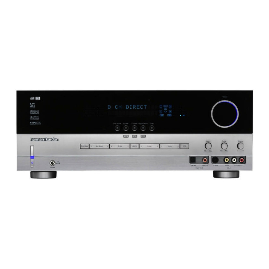
Page 5: Front-Panel Controls
Ô Video 4 Audio Input Jacks Bass Control AVR 235; press it again to turn the unit off. The Power Indicator 3 turns blue when the unit is on. 4 Headphone Jack: This jack may be used to listen to the AVR 235’s output through a pair of headphones. -
Page 6: Front-Panel Controls
! Tuner Band Selector: Press this button to turn the AVR 235 on and to select the Tuner as the input source. Press it again to switch between the AM and FM frequency bands. (See page 29 for more informa- tion on the tuner.) -
Page 7: Rear-Panel Connections
¡ CD Audio Inputs: Connect these jacks to the analog audio output of a compact disc player or changer. ™ Tape Outputs: Connect these jacks to the RECORD/INPUT jacks of an audio recorder. £ Remote IR Input: If the AVR 235’s front-panel REAR-PANEL CONNECTIONS ¶ ª ⁄... - Page 8 (white for front left and red for front right) (+) terminals on the AVR 235 to the red (+) terminals on the speakers and the black (–) terminals on the AVR 235 to the black (–) terminals on the speakers.
- Page 9 Tape Inputs: Connect these jacks to the PLAY/OUT jacks of an audio recorder. AM Antenna Terminals: Connect the AM loop antenna supplied with the receiver to these terminals. If an external AM antenna is used, make connections to the AM and GND terminals, in accordance with the instructions supplied with the antenna.
-
Page 10: Remote Control Functions
EzSet Sensor Microphone NOTE: • The function names shown here are each button’s feature when used with the AVR 235. Most buttons have additional functions when used with other devices. See pages 38–39 for a list of these functions. • To make it easier to follow the instructions that refer to... - Page 11 AVR Selector: Pressing this button will switch the remote so that it will operate the AVR 235’s functions. If the AVR 235 is in the Standby mode, it will also turn the AVR 235 on. g AM/FM Tuner Select: Press this button to select the AVR 235’s tuner as the listening choice.
- Page 12 ` Transport Controls: These buttons do not have any direct functions for the AVR 235, but they may be programmed for the forward/reverse play operation of a wide variety of CD or DVD players, and audio or video cassette recorders.
- Page 13 Channel Direct Input g as the audio source. Mute: Press this button to momentarily silence the AVR 235 or TV set being controlled, depending on which device has been selected. When the AVR 235 remote is being programmed to operate another device, this button is pressed with the Input Selector Button e to begin the programming process.
-
Page 14: Installation And Connections
Digital Audio Inputs ad*(. 4. Connect the coaxial or optical Digital Audio Outputs ‡° on the rear panel of the AVR 235 to the matching digital input connections on a CD-R or MiniDisc recorder. 5. Assemble the AM Loop Antenna supplied with the unit so that the tabs at the bottom of the antenna loop snap into the holes in the base. -
Page 15: Ac Power Connections
However, it will not convert any of these signals to a different format. • When connecting a video source to the AVR 235, you may use composite, component or S-Video, but only one type of video may be connected for each device. -
Page 16: System Configuration
You are now ready to power up the AVR 235 to begin these final adjustments. 1. Make certain that the AC Power Cord › is firmly inserted into an unswitched AC outlet. -
Page 17: Input Setup
“burned into” the projection tubes, plasma screen or CRT. This type of damage is not covered by the AVR 235 warranty and may not be covered by the projector/TV set’s warranty. The AVR 235 has two on-screen display modes, “Semi-OSD”... -
Page 18: Surround Setup
– you may change it later. However, to make it easier to establish the initial parameters for the AVR 235, it is best to select Dolby Pro Logic II or Logic 7 for most analog inputs and Dolby Digital for inputs connected to digital sources. - Page 19 For example, a 48kHz digital source will be processed at 48kHz. However, the AVR 235 allows you to upsam- ple the incoming 48kHz signals to 96kHz for added resolution.
-
Page 20: Speaker Setup
BACK TO MASTER MENU line and press the Set Button p. Speaker Setup This menu tells the AVR 235 which type of speakers are in use. This is important as it adjusts the settings that decide whether your system will use the “5-chan- nel”... - Page 21 “main” speakers. SYSTEM CONFIGURATION SYSTEM CONFIGURATION • If a subwoofer is connected to the AVR 235, you have the option to have the front left/right “main” speakers reproduce bass frequencies at all times,...
-
Page 22: Delay Settings
“sweet spot” position. In addition to adjusting the delay time for each individ- ual speaker position, the AVR 235 is among the few A/V receivers that allows you to adjust the delay for the combined output of all speakers as a group. This feature is called A/V Sync Delay;... -
Page 23: Output Level Adjustment
Output level adjustment is a key part of the configura- tion of any surround sound product. It is particularly important for a digital receiver such as the AVR 235, as correct outputs ensure that you hear soundtracks with the proper directionality and intensity. - Page 24 Lower Display Line T. If the sound from a speaker location does NOT match the position indicated in the display, turn the AVR 235 off using the Main Power Switch 1 and check the speaker wiring or connections to external power amplifiers to make cer- tain that each speaker is connected to the correct out- put terminal.
-
Page 25: Basic Operation
Turning the AVR 235 On or Off • When using the AVR 235 for the first time, you must press the Main Power Switch 1 on the front panel to turn the unit on. This places the unit in a Standby mode, as indicated by the amber color of the Power Indicator 2 . -
Page 26: Digital Audio Playback
(HDTV) system. An optional, external RF demodulator is required to use the AVR 235 to listen to the Dolby Digital sound- tracks available on laser discs. Connect the RF output of the LD player to the demodulator and then connect the digital output of the demodulator to the Optical or Coaxial Inputs *(ad of the AVR 235. -
Page 27: Surround Mode Chart
The Pro Logic mode activates original Pro Logic processing for those who prefer that presentation. Logic 7 Cinema Exclusive to Harman Kardon for A/V receivers, Logic 7 is an advanced mode that extracts the maximum surround information from either Logic 7 Music surround-encoded programs or conventional stereo material. - Page 28 Dolby Pro Logic II or Logic 7. Since the range of available surround modes is dependent on the type of digital data that is present, the AVR 235 uses a variety OPERATION of indicators to let you know what type of signal is present.
-
Page 29: Tuner Operation
DVD player (usually with the “Audio Select” button or in a menu screen on the disc) to send a full 5.1 feed to the AVR 235. It is also possible for the type of signal feed to change during the course of a DVD playback. -
Page 30: Output Level Trim Adjustment
Preset Tuning Using the remote, up to 30 stations may be stored in the AVR 235’s memory for easy recall using the front- panel controls or the remote. To enter a station into the memory, first tune the sta- tion using the steps outlined above. - Page 31 levels are reset, resume the procedure outlined above to reset the levels to the desired settings. When all Buttons n adjustments are done, press the ⁄ ¤ to move the on-screen cursor so that it is next to › BACK TO MASTER MENU and then press the Set Button p if you wish to go back to the main menu to make other adjustments.
-
Page 32: Advanced Features
Turn-On Volume Level As is the case with most audio/video receivers, when the AVR 235 is turned on, it will always return to the volume setting in effect when the unit was turned off. However, you may prefer to always have the AVR 235 turn on at a specific setting, regardless of what was last in use when the unit was turned off. -
Page 33: Default Surround Mode
Dolby Digital or DTS is present. The AVR 235 allows you to set the unit so that it will either respond to the default or switch to your desired mode. -
Page 34: Programming The Remote
Auto Search Method. Auto Search Method If the unit you wish to include in the AVR 235’s remote is not listed in the code tables in this manual or if the code does not seem to operate properly, you may wish... -
Page 35: Programmed Device Functions
Function List and then look in the column for the device you are controlling. For example, button number 46 is the Direct button for the AVR 235, but it is the “Favorite” button for many cable television boxes and satellite receivers. Button number 32 is the Delay button for the AVR 235, but the Open/Close button for CD players. -
Page 36: Volume Punch-Through
TV viewing, you may wish to have the AVR 235’s volume activated, although the remote is set to run the TV. Either the AVR 235 or TV volume control may be associated with any of the remote’s devices. -
Page 37: Resetting The Remote Memory
Example: To use the Video 4 button to operate a satellite receiver, first press the Video 4 Input Selector e and the Mute Button at the same time until the red light glows under the Video 4 Button e. Press the VID2/SAT Button e, followed by the three-digit code for the specific model you wish to control. -
Page 38: Function List
FUNCTION LIST No. Button Name AVR Function Power On Power On Power On Power Off Power Off Power Off Mute Mute Mute AVR Select AVR Select DVD Input Select DVD Select CD Input Select CD Select Tape Tape Input Select Tape Select VID 1 Video 1 Select... - Page 39 No. Button Name AVR Function 45 Tune Up Tune Up Next Chapter Track Direct 46 Direct Direct Tuner Entry Angle 47 Clear Clear Clear 48 Preset Up Preset Tune Up Slow Forward +10 49 Tune Down Tune Down Prev Chapter Track Increment 50 OSD 51 D.
- Page 40 CENTURION CENTRONIC CITIZEN CLASSIC CONCERTO CONTEC CORANDO CORONADO CRAIG CROWN CURTIS MATHES DAEWOO DAYTRON DIGI LINK DYNASTY DYNATECH ELECTROHOME EMERSON FUNAI FUTURETECH GOLDSTAR/LG GRUNDIG HALL MARK HARMAN KARDON HITACHI INFINITY INKEL JC PENNEY JENSEN KAWASHO KENWOOD LLOYTRON LODGENET SETUP CODES...
- Page 41 Manufacturer/Brand Setup Code Number LOGIK LUXMAN MAGNAVOX MARANTZ MATSUI MEMOREX METZ MINERVA MITSUBISHI NATIONAL NIKEI ONKING ONWA OPTONICA ORION PANASONIC PHILCO PHILIPS PIONEER PORTLAND PROSCAN PROTON QUASAR RADIO SHACK REALISTIC RUNCO SAMPO SAMSUNG SANYO SCOTT SEARS SHARP SIEMENS SIGNATURE SONY SOUNDESIGN SPECTRICON SYLVANIA...
- Page 42 SETUP CODE TABLE: TV Manufacturer/Brand Setup Code Number TEKNIKA TELERENT TERA THOMSON TOSHIBA TOTEVISION VIDEO CONCEPTS VIDTECH WARDS YAMAHA YORK YUPITERU ZENITH ZONDA SETUP CODES...
- Page 43 DAYTRON 018 048 DYNATECH EMERSON 013 040 042 110 112 FISHER FUNAI 076 095 124 GO VIDEO GOLDSTAR/LG 018 107 HARMAN KARDON 018 049 HITACHI 040 048 JC PENNEY 018 045 JENSEN 018 048 111 132 KENWOOD 020 048 LLOYD...
- Page 44 SETUP CODE TABLE: VCR Manufacturer/Brand Setup Code Number SALORA SAMSUNG 045 051 095 105 109 SANSUI 048 116 147 SANYO 017 020 SCOTT 110 112 SEARS 017 020 SHARP 129 156 SONY 080 129 SOUNDESIGN SYLVANIA SYMPHONIC TANDY 017 040 TASHICO TATUNG TEAC...
- Page 45 AUDIOFILE CALIFORNIA AUDIO CAPETRONIC CARRERA CARVER 143 144 CASIO CLARINETTE DENON EMERSON FISHER FRABA FUNAI GENEXXA GOLDSTAR/LG HAITAI HARMAN KARDON 054 190 HITACHI INKEL JC PENNEY JENSEN KENWOOD 079 148 LOTTE LUXMAN MAGNAVOX MARANTZ 192 193 MCINTOSH MITSUMI MODULAIRE NAKAMICHI...
- Page 46 YAMAHA 061 135 YORK SETUP CODE TABLE: DVD Manufacturer/Brand Setup Code Number APEX DIGITAL DENON 019 051 003 004 GOLDSTAR/LG HARMAN KARDON 005 055 064 066 MAGNAVOX MARANTZ MITSUBISHI ONKYO 009 048 PANASONIC 024 030 044 PHILIPS PIONEER 041 065...
- Page 47 Manufacturer/Brand Setup Code Number ALPHASTAR ALPHASTAR DBS ALPHASTAR DSR BIRDVIEW CHANNEL MASTER 320 321 CHAPARRAL 315 316 CITOH DRAKE 313 317 413 481 DX ANTENNA 331 352 379 483 ECHOSTAR 395 397 453 463 ELECTRO HOME FUJITSU 324 329 GENERAL INSTRUMENT 303 311 365 403 HITACHI DBS...
- Page 48 SETUP CODE TABLE: TAPE Manufacturer/Brand Setup Code Number HARMAN KARDON SETUP CODE TABLE: CBL Manufacturer/Brand Setup Code Number 001 011 ALLEGRO AMERICAST ARCHER BELCOR CABLE STAR 033 113 CITIZEN COLOUR VOICE 085 090 DIGI EAGLE EASTERN 066 070 ELECTRICORD EMERSON FOCUS G.I.
- Page 49 Manufacturer/Brand Setup Code Number REMBRANT SAMSUNG 072 186 SCIENTIFIC ATLANTA 183 203 221 222 SEAM SIGNATURE 001 188 SPRUCER 053 081 177 189 STARCOM 002 011 163 STARGATE TANDY TELECAPATION TEXSCAN TIMELESS TOCOM 170 205 UNITED CABLE UNIVERSAL 033 034 039 042 113 VIDEOWAY 124 211 VIEWSTAR...
-
Page 50: Troubleshooting
• Additional cooling may not be required In addition to the items shown above, additional information on troubleshooting possible problems with your AVR 235, or installation-related issues, may be found in the list of “Frequently Asked Questions” which is located in the Product Support section of our Web site at www.harmankardon.com. - Page 51 Height measurement includes feet and chassis. All features and specifications are subject to change without notice. Harman Kardon and Power for the Digital Revolution are registered trademarks of Harman International Industries, Incorporated. is a trademark of Harman International Industries, Incorporated (patent no. 5,386,478).
- Page 52 Full-OSD Time-Out 33 Hall 27 Headphones 26 Input-Independent Speaker Setup 21–22 Input Setup 17–18 Installation 14–15 Installation Location 4 IR Receiver 6 INDEX Logic 7 11, 19, 27 Macros 34–35 Manual Mode Tuning 6, 11–12, 30 Master Menu 17 Memory Backup 31...
- Page 53 NOTES NOTES...
- Page 54 NOTES NOTES...
- Page 55 NOTES NOTES...
- Page 56 ® 250 Crossways Park Drive, Woodbury, New York 11797 www.harmankardon.com © 2004 Harman International Industries, Incorporated Part No. CQX1A950Z 8/04...
Need help?
Do you have a question about the AVR 235 and is the answer not in the manual?
Questions and answers
How do i get master menu on the osd display on tv wothout the remote