Table of Contents
Advertisement
Quick Links
Advertisement
Table of Contents

Related Manuals for Arkray AUTION ELEVEN AE-4022


Summary of Contents for Arkray AUTION ELEVEN AE-4022
-
Page 2: Introduction
Follow the instructions in the manual in order to maintain the instrument warranty. © 2015 ARKRAY, Inc. • It is strictly prohibited to copy any part of this reference manual without the expressed consent of ARKRAY, Inc. AE-4022... -
Page 3: Table Of Contents
Table of Contents 1. Introduction ....................i 2. Table of Contents ..................ii 3. PREMISE ......................v Intended Use ....................... v Technology and Scientific Principles................vi Biological Principles*1 ....................viii 4. For Your Safety and Product Performance..........x Electrical Compliance....................x Caution in Handling Specimens .................. - Page 4 2.2. Measurement precautions ..............2-4 2.2.1. Precautions for operation ................2-4 2.2.2. Precautions for handling samples ............. 2-4 2.2.3. Precautions for handling test strips ............2-5 2.3. Preparation for measurement ..............2-6 2.3.1. Check before measurement..............2-6 2.3.2. Starting the instrument ................2-8 2.3.3.
- Page 5 3.7.13. No.010: Number of sheets to print ............3-32 3.7.14. No.011: Number of line breaks ............... 3-33 3.7.15. No.012: Additional data................3-34 3.7.16. No.013: External output ON/OFF............3-35 3.7.17. No.014: Barcode output range setting ............ 3-36 3.7.18. No.016: Operator ID number management..........3-38 3.7.19.
-
Page 6: Premise
The chemical reaction with the urine results in a color change and indicates the concentration of the analyte. The AUTION ELEVEN AE-4022 technology provides fast results that can be used along with other diagnostic information to rule out certain disease states and to determine if microscopic analysis is needed. -
Page 7: Technology And Scientific Principles
Each of the reagent strip pads reflect a given color and shade when immersed in urine which is indicative of the analyte concentration. The strip enters the AUTION ELEVEN AE-4022 where it is auto-aligned and a set of LED’s directs a single wavelength for measurement (635 nm or 565 nm) at each reagent pad on the test strip. - Page 8 Adding the shades light, normal, and dark (based on COLORLESS wavelengths 430 nm and 760 nm) to each of the colors YELLOW ORANGE (yellow, orange, brown, red, violet, blue and green), 21 color BROWN tones are created. There are 23 color tones altogether LIGHT including those categorized as non-reflective ‘Colorless’, and, VIOLET...
-
Page 9: Biological Principles*1
Biological Principles* Glucose Glucose concentration in urine can be indicative of (1) a prerenal condition (hyperglycemia), or (2) a renal condition. Causes for the prerenal condition could include the following: diabetes mellitus, hormonal disorders (such as hyperthyroidism, acromegaly, stress, anxiety, Cushing’s disease), liver disease, pancreatic disease, central nervous system damage, or drugs (namely thiazide, diuretics, or steroids). - Page 10 Blood Hematuria is an abnormal amount of red blood cells in the urine, possibly caused by renal and urinary tract disease, extrarenal disease, trauma, strenuous exercise, or drugs. Hemoglobinuria indicates the presence of hemoglobins, which may be caused by intravascular hemolysis, extensive burns, strenuous exercise, or infections.
-
Page 11: For Your Safety And Product Performance
For Your Safety and Product Performance Electrical Compliance This product conforms to the EMC Standard IEC61326-2-6:2012. Class of emission: CISPR 11 Class A For In Vitro Diagnostic Use. NOTE: This instrument has been tested and found to comply with the limits for a Class A digital device, pursuant to part 15 of the FCC Rules. -
Page 12: Symbols
Symbols Symbol Meaning To avoid Personal Injury Follow the instructions given here to prevent exposure to pathogenic microorganisms. Follow the instructions given here to prevent injury and property damage. Follow the instructions given here to prevent pinch points. Follow the instructions given here to prevent burns from hot surfaces. To avoid Damage to the Product or its Performance IMPORTANT: Follow the instructions given here to obtain accurate measurement results. -
Page 13: Caution Labels
Caution Labels This instrument has several caution labels on the areas that have potential dangers. Please learn potential dangers warned by each label and observe the precautions described below. a Carrying arm The carrying arm moves during measurement. While the carrying arm is moving, do not put your hand close to the arm so as to avoid being caught or pinched. - Page 14 d Waste box Never touch with unprotected hands the waste box, where the sample may adhere. During cleaning or maintenance of the waste box, wear protective gloves to prevent exposure to pathogenic microorganisms. e Motor Do not touch the motor and its surrounding area, which may be hot and cause burn on the hand, especially during operation and just after the instrument is turned off.
-
Page 15: Environmental Conditions
Environmental Conditions Storage conditions Temperature: 1 to 30°C, Humidity: 20 to 80% R.H. (non-condensing) Shipping conditions Temperature: -10 to 60°C, Humidity: 20 to 80% R.H. (non-condensing) Operating conditions Temperature: 10 to 30°C, Humidity: 20 to 80% R.H. (non-condensing) ... -
Page 16: Materials Provided
Materials Provided Items in the package a Instrument b Accessory kit box Name Description Qty. Instrument AE-4022 Accessory kit box See below. Accessory kit box a Test strip tray b Check strip set c Thermal recording paper d AC adapter e Power cord f Operating manual Name... -
Page 17: Materials Necessary
Commercial Control solution for use with urine analyzers Quality Control Performance of the AUTION ELEVEN AE-4022 and the AUTION Sticks 10EA should be confirmed regularly utilizing both known negative and known positive urine specimens or control materials. Adhere to all regulations applicable to the practice region as well as manufacturers’... - Page 18 Before Using the AE-4022 Chapter 1 Outline of the AE-4022.................. 1-2 1.1.1. AE-4022 Features .....................1-2 1.1.2. Measurement types ...................1-4 1.1.3. Specifications ....................1-5 Name and function of each part ..............1-6 1.2.1. Front side ......................1-6 1.2.2. Rear side ......................1-7 1.2.3. Display.......................1-8 1.2.4.
-
Page 19: Chapter 1 Before Using The Ae-4022
Chapter 1 Before Using the AE-4022 Outline of the AE-4022 1.1.1 AE-4022 Features Compact and lightweight, with simple structure The instrument has a minimal installation footprint of just the area of an A4-size sheet of paper. It can be installed in various locations and can be carried easily, thanks to its lightweight construction and minimal weight of approx. - Page 20 Outline of the AE-4022 Abnormal color detection The instrument has an abnormal color detection function that detects abnormal color generation on the reagent pad. The instrument prints a “!” mark with the measurement result (only applicable to measurement items KET, BIL, and URO).
-
Page 21: Measurement Types
Chapter 1 Before Using the AE-4022 1.1.2 Measurement types Normal measurement In the normal measurement mode, samples are measured consecutively. Measurements in this mode are allocated MEAS No. * * * *. After the measurement number of the first sample is entered, the system automatically increments the number by one for each subsequent measurement. -
Page 22: Specifications
Outline of the AE-4022 1.1.3 Specifications Sample Urine Test Strip / Reagent pack AUTION Sticks 10EA Measurement item GLU, KET, BIL, NIT, PRO, URO, pH, BLD, LEU, Specific Gravity, color tone Measurement range Test strip: Rank table (See “6.1. Rank tables” on page 6-2) Color tone: Color tone classification chart (See “Technology and Scientific Principles”... -
Page 23: Name And Function Of Each Part
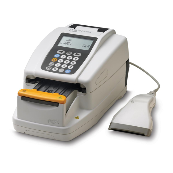
Chapter 1 Before Using the AE-4022 Name and function of each part 1.2.1 Front side The maintenance cover closed The maintenance cover opened Name Function Display Displays information such as operating status and error messages. Operator panel Used to start and stop measurement as well as to input numeric values. Built-in printer Thermal line printer for printing measurement results and parameter setting details. -
Page 24: Rear Side
Name and function of each part 1.2.2 Rear side Name Function Power switch Turns the instrument ON/OFF. Power input terminal For connection with the supplied AC adapter. B.C.R. Terminal for the optional hand-held barcode reader. RS-232C Terminal for an external device. Ethernet (optional) For connection to an Ethernet unit. -
Page 25: Display
Chapter 1 Before Using the AE-4022 1.2.3 Display Standby screen When the instrument is turned ON, the [Standby screen] appears. Name Function Measurement mode The currently selected measurement mode is shown with an icon. To change the measurement mode, press when the [Standby screen] is displayed. - Page 26 Name and function of each part The function of each icon is noted below. Icon Name Function See page MODE icon Selected to change the measurement mode. MEMORY icon Selected to reprint or resend measurement results. DATE icon Selected to set the date and time. 3-11 LIST icon Selected to print an abnormal measurement results list.
-
Page 27: Operator Panel
Chapter 1 Before Using the AE-4022 1.2.4 Operator panel Name Function START Press to start measurement. STOP Press to interrupt measurement, a menu function, setting, or to cancel an input operation. FEED Thermal recording paper is fed to the built-in printer while this key is pressed. -
Page 28: Installing The Instrument
Installing the instrument Installing the instrument 1.3.1 Precautions for installation Before installing the instrument, read the following items and always take proper safety precautions. Install the instrument at least 20 cm away from walls. Inadequate clearance between the instrument and walls may cause overheating of the instrument or undesirable load on cable connections, thus resulting in fire or incorrect measurement results. -
Page 29: Installation Of The Instrument
Chapter 1 Before Using the AE-4022 1.3.2 Installation of the instrument Certain components are held securely using fixing tape to protect the instrument from damage during transportation. The tapes must be removed and these security measures released to install the system and prepare the instrument for use. - Page 30 Installing the instrument Release the suction ports a Remove the fixing tape from the suction ports. Fixing tape Suction ports NOTE: After removing the fixing tape, press the suction ports with your finger and ensure that the part is securely fixed in its proper position.
- Page 31 Chapter 1 Before Using the AE-4022 Release the printer cover a Remove the fixing tape from the printer cover on the back of the instrument. Fixing tape Release the waste box a Remove the fixing tape from the waste box on the back of the instrument.
- Page 32 Installing the instrument Connect an external device (if necessary) REFERENCE: Use an appropriate connection cable (option) when connecting an external device. a Connect the cable from the external device to the RS-232C RS-232C terminal on the back of the instrument. Tighten the terminal screws.
-
Page 33: Starting And Ending Operation After Installation
Chapter 1 Before Using the AE-4022 1.3.3 Starting and ending operation after installation This section describes the startup process of the instrument, how to set the thermal recording paper, and how to set the date and time. NOTE: When the instrument is turned ON, the carrying arm repeats the test strip feeding movement. Ensure that nothing on the test strip tray obstructs the carrying arm movement. - Page 34 Installing the instrument e After 20 seconds, the warm-up process ends, and the [Standby screen] appears. The currently selected measurement mode, test strip type, and measurement number appear on the display screen. NOTE: An error or problem is indicated by a buzzer alarm and a message on the screen, as shown in the right figure.
- Page 35 Chapter 1 Before Using the AE-4022 Turn OFF the instrument a At the end of work, or when you will not be performing measurements or making settings, turn OFF the instrument after first checking that the [Standby screen] is displayed. AE-4022 1-18...
-
Page 36: Chapter 2 Measurement Operation
Measurement Operation Chapter 2 Outline of measurement operation ............. 2-2 2.1.1. Measurement operational flow ................2-2 2.1.2. Measurement ....................2-3 Measurement precautions ................2-4 2.2.1. Precautions for operation ..................2-4 2.2.2. Precautions for handling samples ..............2-4 2.2.3. Precautions for handling test strips ..............2-5 Preparation for measurement .............. -
Page 37: Outline Of Measurement Operation
Chapter 2 Measurement Operation Outline of measurement operation This instrument measures samples and Controls. This chapter describes the operational flow and outline of each measurement mode. 2.1.1 Measurement operational flow Check before measurement Check used test strips Turn ON the instrument Check the feeder Check the thermal recording paper To change settings... -
Page 38: Measurement
Outline of measurement operation 2.1.2 Measurement Measurement mode This instrument has four types of measurement modes: “Normal measurement”, “STAT measurement”, “Control measurement” and “Check measurement”. Press on the [Standby screen] to change the measurement mode. The figures below show the appearance of the [Standby screen] for each of the four measurement modes. Normal measurement mode STAT measurement mode Control measurement mode... -
Page 39: Measurement Precautions
Chapter 2 Measurement Operation Measurement precautions 2.2.1 Precautions for operation Always use the instrument in the proper operating environment. Before turning ON the instrument, check that the “1.3.1. Precautions for installation” explained on page 1-11 have been followed. In the ambient temperature range of 10 to 30 °C, the temperature correction function operates to give the most accurate measurement results possible. -
Page 40: Precautions For Handling Test Strips
Precautions for handling test strips Use only ARKRAY’s test strips designed for the AUTION ELEVEN The AUTION ELEVEN works with special test strips designed and made by ARKRAY, Inc. Thoroughly read the test strip package insert and use them by the expiry date. -
Page 41: Preparation For Measurement
Chapter 2 Measurement Operation Preparation for measurement Before starting measurement, check the waste box, feeder, and thermal recording paper. Wear protective gloves to prevent exposure to pathogenic microorganisms. Discard used test strips in accordance with local regulations for biohazardous waste. NOTE: The special test strips for the AUTION ELEVEN do not come with the instrument. - Page 42 Preparation for measurement Check the feeder a Check for the presence of crystallized surplus urine adhering to the test strip tray. If you find any, wipe it off and clean the area. Maintenance cover Test strip tray Close the maintenance cover a Close the maintenance cover until it clicks closed.
-
Page 43: Starting The Instrument
Chapter 2 Measurement Operation 2.3.2 Starting the instrument This section describes the instrument’s operation from the time it is turned ON until the [Standby screen] is displayed. NOTE: When the instrument is turned ON, the carrying arm repeats the test strip feeding movement. Ensure that nothing on the test strip tray obstructs the carrying arm movement. - Page 44 Preparation for measurement NOTE: An error or problem is indicated by a buzzer alarm and a message on the screen, as shown in the right figure. See “Chapter 5. Troubleshooting” to solve the error or problem. AE-4022...
-
Page 45: Setting Measurement Conditions
Chapter 2 Measurement Operation 2.3.3 Setting measurement conditions Before starting measurement, set the measurement conditions as required. If you wish to use the same measurement conditions as the last time, you need not set them again. See “Chapter 3. Supplementary Operations” for explanations concerning how to set individual items. - Page 46 Preparation for measurement Item No Setting item Description Standard value pages No.019 Printing of operator ID Specifies whether to print operator ID numbers with 3-46 numbers with results measurement results. No.020 QC deadline Specifies the deadlines for QC (control – 3-47 measurement).
-
Page 47: Entering Your Operator Id Number
Chapter 2 Measurement Operation 2.3.4 Entering your operator ID number When the operator ID function is ON, you need to enter your operator ID number before performing a test. Call up the screen a With the [Standby screen] displayed, press and hold for 3 seconds. -
Page 48: Sample Preparation
Preparation for measurement 2.3.5 Sample preparation Prepare samples according to the following steps, referring to “2.2.2. Precautions for handling samples” on page 2-4. Wear protective gloves to prevent exposure to pathogenic microorganisms. Preparing samples Prepare sufficient sample. IMPORTANT: Prepare a sufficient volume of samples so that the entire test strip pad area can be dipped in a single movement. -
Page 49: Entering Patient Id Numbers
Chapter 2 Measurement Operation 2.3.6 Entering patient ID numbers Each patient ID number can have up to 13 digits of numeric figures and “–” characters entered. The patient ID number entered is uniquely allocated to the measurement made just after this entry is made. After a group of measurements is completed, the patient ID numbers are automatically deleted. - Page 50 Preparation for measurement b Press • The recorded patient ID number is stored and the display returns to the [Standby screen]. • Once the patient ID number is set, the “measurement number + test strip type” and “patient ID number” are displayed alternately on the [Standby screen].
- Page 51 Chapter 2 Measurement Operation b Press • The entered patient ID number is stored and the display returns to the [Standby screen]. • Once the patient ID number is set, the “measurement number + test strip type” and “patient ID number” are displayed alternately on the [Standby screen].
-
Page 52: Measurement Operation
Measurement operation Measurement operation 2.4.1 Normal measurement Normal measurement mode is used for consecutive measurement of samples. To measure one or more urgent samples immediately during a normal measurement process, press to switch to the STAT measurement mode. Wear protective gloves to prevent exposure to pathogenic microorganisms. Prepare the samples a Prepare the samples, referring to “2.3.5. - Page 53 Chapter 2 Measurement Operation Prepare test strips REFERENCE: The currently set test strip type is displayed on the [Standby screen]. To change the test strip type, please refer to “3.7.5. No.002: Test strip type” on page 3-22. a Take out the required number of test strips from the bottle. b Close the test strip bottle cap securely.
- Page 54 Measurement operation Call up the [Clarity input screen] a Press and hold for about 2 seconds. • The [Clarity input screen] appears. Enter the clarity value a Enter the clarity value of the sample using the numeric keys. • Enter a number between 1 and 5 using the table below. Input No.
- Page 55 Chapter 2 Measurement Operation REFERENCE: If the buzzer setting is ON, follow the timing chart below. Slow beeping Fast beeping Preparation for dipping: Dipping period: Test strip setting: 3 seconds 2 seconds 1.4 seconds Place the test strip on the test strip tray a Immediately place the test strip on the test strip tray holding the strip in a horizontal position to prevent possible mixing of chemicals from adjacent reagent areas and/or contaminating the...
- Page 56 Measurement operation 10 Prepare the next sample and test strip a Repeat steps 6 and 9 for entering the clarity value, and dipping and setting subsequent test strips. • When a test strip is placed, the system automatically starts the measurement of the next sample.
-
Page 57: Stat Measurement
Chapter 2 Measurement Operation 2.4.2 STAT measurement The STAT measurement mode, like the normal measurement mode, measures samples consecutively. The STAT measurement mode can also be used for measuring urgent samples during normal measurement. With the [Standby screen] or [Measurement screen] displayed, press to switch to the STAT measurement mode. - Page 58 Measurement operation Set the measurement number After the first sample is allocated a 4-digit measurement number, the system automatically increments the measurement number by one. The measurement numbers are stored in the system until the power is turned OFF. To set the first measurement number to “0001”, do not enter a measurement number, but follow the procedure in step 4 below.
- Page 59 Chapter 2 Measurement Operation Start the STAT measurement IMPORTANT: Different procedures at this stage are required, depending on the setting of the “operational mode when turning ON” parameter. (See “ Operational mode” on page 2-3.) The standard setting is “Auto start” mode. To change the “operational mode when turning ON”, see “3.7.8.
- Page 60 Measurement operation Place the test strip on the test strip tray a Place the test strip on the test strip tray. In the auto start mode, the instrument makes a beep sound when detecting a test strip. Then the carrying arm moves the test strip to the suction ports. After surplus urine has been removed, the test strip is fed through the test strip feed mechanism to the photometric section.
- Page 61 Chapter 2 Measurement Operation 10 Finish STAT measurement a When the STAT measurement finishes, the display returns to the [Standby screen]. The measurement and patient ID numbers for the next measurement are displayed on the [Standby screen]. AE-4022 2-26...
-
Page 62: Control Measurement
Measurement operation 2.4.3 Control measurement Controls should be used daily, whenever a new bottle of strips is opened, before reporting unusual or unexpected results, and when training new operators. Refer to the control solution package insert for expected values. Each laboratory should establish its own goals for adequate standards of performance by following local, state and federal requirements when establishing their QC program. - Page 63 Chapter 2 Measurement Operation Set a measurement number After the first sample is allocated a 4-digit measurement number, the system automatically increments the measurement number by one. The measurement numbers are then stored in the system until the power is turned OFF. To set the first measurement number to “0001”, do not enter a measurement number, but follow the procedure in step 4 below.
- Page 64 Measurement operation Start the Control measurement IMPORTANT: Different procedures at this stage are required, depending on the setting of the “operational mode when turning ON” parameter. (See “ Operational mode” on page 2-3.) The standard setting is “Auto start” mode. To change the “operational mode when turning ON”, see “3.7.8.
- Page 65 Chapter 2 Measurement Operation Place the test strip on the test strip tray a Immediately place the test strip on the test strip tray holding the strip in a horizontal position to prevent possible mixing of chemicals from adjacent reagent areas and/or contaminating the hands with urine.
- Page 66 Measurement operation End Control measurement a When the Control measurement finishes, the display returns to the [Standby screen]. The measurement and patient ID numbers for the next measurement are displayed on the [Standby screen]. AE-4022 2-31...
-
Page 67: Check Measurement
Chapter 2 Measurement Operation 2.4.4 Check measurement Check measurement is conducted using the check strips that are included with the instrument, to confirm the system status. The check strip bottle contains two gray and two white check strips. Use one test strip of each color for this measurement procedure. - Page 68 Measurement operation b Press to switch to check measurement mode. • On the [Standby screen], the icon is displayed, and the measurement mode is switched to the Check measurement mode. Prepare the check strips a Prepare the check strips. The check strip bottle has a reflectance Check strip (white) label on it, which must be used when evaluating reflectance after the check measurement.
- Page 69 Chapter 2 Measurement Operation • When using the “Cycle start” mode, press to start the check measurement of the first strip. • In the “Auto start” mode, the system automatically starts the check measurement of the first strip when placement of the check strip is detected.
- Page 70 Measurement operation Remove the check strips a Pull out the waste box to remove the check strips from the instrument. b Return the check strips to the check strip bottle for safekeeping. Check strips Evaluate reflectance See the samples of the printed check measurement results on the next page. Check that the reflectance at each wavelength printed for the check measurement result is within the ranges written on the reflectance label.
- Page 71 Chapter 2 Measurement Operation Check measurement results Measurement mode Serial number of the instrument Date and time of measurement Wavelength Reflectance When unwanted light entered the instrument and prevented proper measurement When the check strip was not placed in the correct position and proper measurement was impossible AE-4022 2-36...
-
Page 72: How To Read The Measurement Results
How to read the measurement results How to read the measurement results When the measurement result format is “semiquantitative”. MEAS Normal measurement Measurement STAT STAT measurement mode CONTROL Control measurement Measurement number Used test strip name Patient ID number Date and time of Internal system temperature measurement... - Page 73 Chapter 2 Measurement Operation When the operator ID function is ON: Operator ID 1234567890123 Operator ID number When the clarity input function is ON: Clarity CLAR Clear AE-4022 2-38...
- Page 74 How to read the measurement results When the selected measurement result format is “reflectance”: Reflectance AE-4022 2-39...
- Page 75 Chapter 2 Measurement Operation AE-4022 2-40...
-
Page 76: Chapter 3 Supplementary Operations
Supplementary Operations Chapter 3 Outline of menu screen ................3-2 3.1.1. How to operate the menu screen ..............3-2 3.1.2. Menu list ......................3-3 MODE (measurement mode selection) ............3-4 MEMORY (reprinting and resending measurement results) ..... 3-6 DATE (setting the date and time)............... 3-11 LIST (printing a list of abnormal measurement results)...... -
Page 77: Outline Of Menu Screen
Chapter 3 Supplementary Operations Outline of menu screen This system has six menus, each of which is represented by an icon displayed in a group at the top of the menu screen. By selecting the icon of the menu you wish to work with, you can switch to the setup screen for that menu and then make the appropriate settings. -
Page 78: Menu List
Outline of menu screen 3.1.2 Menu list The following lists the six menus and their purpose. Menu Icon Description Pages MODE Measurement mode selection MEMORY Reprinting and resending measurement results DATE Setting the date and time 3-11 LIST Printing a list of abnormal measurement results 3-13 STRIP Selecting the test strip type... -
Page 79: Mode (Measurement Mode Selection)
Chapter 3 Supplementary Operations MODE (measurement mode selection) Use the MODE menu to choose or change the measurement mode. See section “2.4. Measurement operation” on page 2-17 for details concerning the measurement method for each mode. REFERENCE: If you press during operation or input, the current setting is canceled and the display returns to the [Menu screen]. - Page 80 MODE (measurement mode selection) Quit the MODE menu (measurement mode selection) a Press • The display returns to the [Standby screen]. REFERENCE: When the [Standby screen] is displayed, you can change the measurement mode directly by pressing You can toggle between the Normal and STAT measurement modes by pressing when in either of these two measurement modes.
-
Page 81: Memory (Reprinting And Resending Measurement Results)
Chapter 3 Supplementary Operations MEMORY (reprinting and resending measurement results) Use the MEMORY menu to reprint or resend measurement data (of up to 520 samples) stored in the instrument’s memory. The stored measurement results are classified by measurement mode and by measurement result. To reprint or resend the data, specify the “measurement period”, “measurement mode”, “sample”, and “measurement result type”... - Page 82 MEMORY (reprinting and resending measurement results) Specify the start date of the measurement period a Use to move the flashing indicator, and use the numeric keys to enter the start date of the measurement period to be reprinted or resent. •...
- Page 83 Chapter 3 Supplementary Operations Select the sample extraction method a Press several times until the desired method for extracting samples flashes. • : Extracts all samples : Extracts by patient ID number : Extracts by measurement number b Press • If is selected, the [Measurement result type selection screen] appears.
- Page 84 MEMORY (reprinting and resending measurement results) 10 Select the search result type a Press several times until the desired measurement result type flashes. • : All the measurement results : Measurement results of normal samples : Measurement results of abnormal samples REFERENCE: Different screens appear, depending on the sample data extraction method selected in step 7.
- Page 85 Chapter 3 Supplementary Operations 12 Quit this menu a Press • The display returns to the [Standby screen]. AE-4022 3-10...
-
Page 86: Date (Setting The Date And Time)
DATE (setting the date and time) DATE (setting the date and time) Use the DATE menu to set the date and time. After setting the date and time, you will not need to set them again until after a long period of use, when a deviation may indicate the need for adjustment. REFERENCE: If you press during operation or input, the current setting is canceled and the display returns to the [Menu... - Page 87 Chapter 3 Supplementary Operations Set the time a Use to move the flashing indicator, and use the numeric keys to enter current time. • Hour or minute that can be entered blinks. b Press • The entered time is confirmed, and the [Menu screen] appears. Quit the date and time setting menu a Press •...
-
Page 88: List (Printing A List Of Abnormal Measurement Results)
LIST (printing a list of abnormal measurement results) LIST (printing a list of abnormal measurement results) Use the LIST menu to print a list of measurement results, along with sample error marks “*” and measurement error marks “?”, extracted from the records of up to 520 samples stored in the system. See “2.5. How to read the measurement results”... - Page 89 Chapter 3 Supplementary Operations Quit the LIST setup menu a Press • The display returns to the [Standby screen]. AE-4022 3-14...
-
Page 90: Strip (Selecting The Test Strip Type)
STRIP (selecting the test strip type) STRIP (selecting the test strip type) Use the STRIP menu to select the type of test strips to use in each measurement mode. REFERENCE: If you press during operation or input, the current setting is canceled and the display returns to the [Menu screen]. - Page 91 Chapter 3 Supplementary Operations Select which test strip to use a Using , select the test strip type to be used in the current measurement mode. b Press • The test strip type is confirmed, and the display returns to the [Menu screen].
-
Page 92: Setup (User Settings)
SETUP (user settings) SETUP (user settings) Use the SETUP menu to set the detailed conditions for measurements, printing, and external output. To change the settings for a specific item, enter the desired user setting item number, using the [Item number input screen] to call up the setting screen for that particular item. -
Page 93: List Of Settable Items
Chapter 3 Supplementary Operations 3.7.2 List of settable items The details for each item number are as follows. Item No. Item Description Standard value page No.000 Printing of parameter item Prints the parameter item number, parameter item, – 3-20 numbers specified range, or selected item. - Page 94 SETUP (user settings) Item No. Item Description Standard value page No.019 Printing of operator ID Specifies whether to print operator ID numbers 3-46 numbers with results with measurement results. No.020 QC deadline Specifies the deadlines for QC (control – 3-47 measurement).
-
Page 95: 000: Printing Of Parameter Item Numbers
Chapter 3 Supplementary Operations 3.7.3 No.000: Printing of parameter item numbers Use this submenu item to print parameter item numbers, parameter items, specified ranges or selected items. Refer to the printed material to change the user settings. REFERENCE: If you press during operation or input, the current setting is canceled and the display returns to the [Item number input screen]. -
Page 96: 001: Printing Of Parameters
SETUP (user settings) 3.7.4 No.001: Printing of parameters Use this submenu item to print the current settings for each parameter item number, if you need to verify them. REFERENCE: If you press during operation or input, the current setting is canceled and the display returns to the [Item number input screen]. -
Page 97: 002: Test Strip Type
Chapter 3 Supplementary Operations 3.7.5 No.002: Test strip type Use this submenu to select the test strip type for each measurement mode. The sequence of measurement modes when making these settings is “Normal measurement”, “STAT measurement”, and “Control measurement”. REFERENCE: If you press during operation or input, the current setting is canceled and the display returns to the [Item number input screen]. - Page 98 SETUP (user settings) Select the test strip type to be used in the control measurement mode a Press to display the desired test strip type to be used in the control measurement mode. b Press • The test strip type used in the control measurement mode is confirmed and the display returns to the [Item number input screen].
-
Page 99: 003: Measurement Result Format
Chapter 3 Supplementary Operations 3.7.6 No.003: Measurement result format Use this submenu to select a measurement result format for each measurement mode, namely “semiquantitative value” or “reflectance”. The sequence of measurement modes when making these settings is “Normal measurement”, “STAT measurement”, and “Control measurement”. - Page 100 SETUP (user settings) Select the measurement results format for the STAT measurement mode a Select the measurement results format for the STAT measurement mode, using the numeric keys. b Press • The measurement result format for the STAT measurement mode is confirmed and the [Measurement result format setting screen] for the control measurement mode appears.
-
Page 101: 004: Test Strip Placing Direction
Chapter 3 Supplementary Operations 3.7.7 No.004: Test strip placing direction Use this submenu to select the direction for placing test strips on the test strip tray. REFERENCE: If you press during operation or input, the current setting is canceled and the display returns to the [Item number input screen]. -
Page 102: 005: Operational Mode When Turning On
SETUP (user settings) 3.7.8 No.005: Operational mode when turning ON Use this submenu to set the operational mode when the instrument is turned ON. See the explanation of the operational modes in the “ Operational mode” on page 2-3. REFERENCE: If you press during operation or input, the current setting is canceled and the display returns to the [Item number input screen]. -
Page 103: 006: Buzzer Sound On/Off
Chapter 3 Supplementary Operations 3.7.9 No.006: Buzzer sound ON/OFF Use this submenu to select whether to sound the buzzer that indicates the dipping timing for test strips during measurement. REFERENCE: If you press during operation or input, the current setting is canceled and the display returns to the [Item number input screen]. -
Page 104: 007: Printing Of Abnormal Marks
SETUP (user settings) 3.7.10 No.007: Printing of abnormal marks Use this submenu to select whether to print/output abnormal marks (the abnormal mark “*” or the abnormal color mark “!”) with the measurement results when abnormal values are detected in samples. Please note that the abnormal color mark will only print with the KET, BIL, and URO items when the measurement results are abnormal. -
Page 105: 008: Initialization Of Measurement Number When Turning On
Chapter 3 Supplementary Operations 3.7.11 No.008: Initialization of measurement number when turning ON Use this submenu to specify whether the measurement number is initialized when the instrument is turned ON. REFERENCE: If you press during operation or input, the current setting is canceled and the display returns to the [Item number input screen]. -
Page 106: 009: Printer Use
SETUP (user settings) 3.7.12 No.009: Printer use Use this submenu to specify whether to use the built-in printer. The measurement results stored in memory can be printed using the reprinting function, even if the built-in printer use is set to OFF. REFERENCE: If you press during operation or input, the current setting is canceled and the display returns to the [Item... -
Page 107: 010: Number Of Sheets To Print
Chapter 3 Supplementary Operations 3.7.13 No.010: Number of sheets to print Use this submenu to set the number of sheets used to print the measurement results. REFERENCE: If you press during operation or input, the current setting is canceled and the display returns to the [Item number input screen]. -
Page 108: 011: Number Of Line Breaks
SETUP (user settings) 3.7.14 No.011: Number of line breaks Use this submenu to set the number of line breaks to be made between two printed measurement results. This setting adjusts the bottom margin (the number of breaks between the last line and the cutoff line). REFERENCE: If you press during operation or input, the current setting is canceled and the display returns to the [Item... -
Page 109: 012: Additional Data
Chapter 3 Supplementary Operations 3.7.15 No.012: Additional data Use this submenu to specify additional data to be printed with the measurement results. REFERENCE: If you press during operation or input, the current setting is canceled and the display returns to the [Item number input screen]. -
Page 110: 013: External Output On/Off
SETUP (user settings) 3.7.16 No.013: External output ON/OFF Use this submenu to specify whether to output the measurement results to an external device. REFERENCE: If you press during operation or input, the current setting is canceled and the display returns to the [Item number input screen]. -
Page 111: 014: Barcode Output Range Setting
Chapter 3 Supplementary Operations 3.7.17 No.014: Barcode output range setting Before using the optional hand-held barcode reader, set “the first digit to read” and “the number of digits to read”. The hand-held barcode reader designed for this instrument can read 32-digit barcodes, but can store or output only up to 13 digits. - Page 112 SETUP (user settings) Quit the SETUP menu a Press twice. • The display returns to the [Standby screen]. AE-4022 3-37...
-
Page 113: 016: Operator Id Number Management
Chapter 3 Supplementary Operations 3.7.18 No.016: Operator ID number management Use this submenu to register new operator ID numbers, delete unnecessary operator ID numbers, or print a list of all operator ID numbers. REFERENCE: Up to 150 operator ID numbers can be registered. ... - Page 114 SETUP (user settings) To register a new operator ID number: Call up the operator ID number input screen a Press for operator ID number registration. • The [Operator ID number input screen] appears. Enter a new operator ID number a Enter a new operator ID number.
- Page 115 Chapter 3 Supplementary Operations Set the measurement authority a Select ON or OFF for the measurement authority beyond the QC deadline, using the numeric keys. • 0 : OFF (Measurement is denied) 1 : ON (Measurement is allowed) b Press •...
- Page 116 SETUP (user settings) To delete an operator ID number: Call up the operator ID number input screen a Press for operator ID number deletion. • The [Operator ID number input screen] appears. Enter the operator ID number a Enter the operator ID number you want to delete. b Press •...
- Page 117 Chapter 3 Supplementary Operations To print a list of operator ID numbers: Start printing a Press for printing. • A list of the operator ID numbers is printed. Example: A list of operator ID numbers #001 1234567890123 [1. 0] #002 987655412333 [1.
-
Page 118: 017: Operator Id Function On/Off
SETUP (user settings) 3.7.19 No.017: Operator ID function ON/OFF Use this submenu to specify whether to use the operator ID function. NOTE: When the operator ID function is ON, you need to enter your operator ID number each time: • the power is turned ON, or •... - Page 119 Chapter 3 Supplementary Operations Select ON or OFF for the operator ID function a Select whether to use the operator ID function, using the numeric keys. • 0 : OFF 1 : ON b Press • The ON or OFF setting for the operator ID function is confirmed, and the display returns to the [Item number input screen].
-
Page 120: 018: Operator Id Number Effective Time
SETUP (user settings) 3.7.20 No.018: Operator ID number effective time Use this submenu to set the number of seconds in which the current operator ID number is effective during standby. NOTE: If the [Standby screen] is displayed for longer than the set effective time, you need to reenter your operator ID number before performing a test. -
Page 121: 019: Printing Of Operator Id Numbers With Results
Chapter 3 Supplementary Operations 3.7.21 No.019: Printing of operator ID numbers with results Use this submenu to select whether to print the operator ID numbers with the measurement results. REFERENCE: If you press during operation or input, the current setting is canceled and the display returns to the [Item number input screen]. -
Page 122: 020: Qc Deadline
SETUP (user settings) 3.7.22 No.020: QC deadline Use this submenu to specify the deadlines for QC (control measurement). REFERENCE: The QC deadline is set as a day of the week and time (i.e. Monday 8:00). When the set time on the set date is reached, the instrument locks itself to prevent measurement operations. - Page 123 Chapter 3 Supplementary Operations Set the day of the week a Select the day of the week for the first deadline, using the numeric keys. • 0: Everyday 1: Monday 2: Tuesday 3: Wednesday 4: Thursday 5: Friday 6: Saturday 7: Sunday b Press •...
- Page 124 SETUP (user settings) Set the day of the week a Select the day of the week for the second QC deadline, using the numeric keys. If you use one QC deadline, select “9: No setting”. • 0: Everyday 1: Monday 2: Tuesday 3: Wednesday 4: Thursday...
-
Page 125: 021: Qc Lock-Out Function On/Off
Chapter 3 Supplementary Operations 3.7.23 No.021: QC lock-out function ON/OFF Use this submenu to specify whether to use the QC lock-out function. NOTE: When the QC lock-out function is ON, only the control measurement mode can be selected once the QC deadline has elapsed. - Page 126 SETUP (user settings) Select ON, OFF, or Prompt for the QC lock-out function a Select one of the following options, using the numeric keys. • 0: OFF 1: ON 2: Prompt b Press • The setting for the QC lock-out function is confirmed, and the display returns to the [Item number input screen].
-
Page 127: 022: Clarity Input Function On/Off
Chapter 3 Supplementary Operations 3.7.24 No.022: Clarity input function ON/OFF Use this submenu to specify whether to input the clarity value for each measurement. REFERENCE: When the clarity input function is ON, the clarity value (manually entered) is printed with measurement results. ... -
Page 128: 090: Printing Of A Trouble List
SETUP (user settings) 3.7.25 No.090: Printing of a trouble list Use this submenu to print the trouble history as a list. REFERENCE: If you press during operation or input, the current setting is canceled and the display returns to the [Item number input screen]. -
Page 129: 099: Initialization Of Parameters
Chapter 3 Supplementary Operations 3.7.26 No.099: Initialization of parameters This submenu is used to return the parameter settings to their standard values. The standard values for the parameters are shown in “3.7.2. List of settable items” on page 3-18. REFERENCE: If you press during operation or input, the current setting is canceled and the display returns to the [Item number input screen]. - Page 130 Maintenance Chapter 4 Daily maintenance ..................4-2 4.1.1. Cleaning the feeder ...................4-2 4.1.2. Cleaning the waste box ...................4-10 Replacing the thermal recording paper ............ 4-12 Maintenance of the instrument when it will not be used for a long period..4-15 AE-4022...
-
Page 131: Chapter 4 Maintenance
Chapter 4 Maintenance Daily maintenance At the end of each working day, turn OFF the instrument, and then clean the feeder, and the waste box. 4.1.1 Cleaning the feeder Sample residue often builds up on the test strip tray, carrying arm, suction ports, and test strip feed mechanism, as these parts carry test strips. - Page 132 Daily maintenance Detach the carrying arm a Pull the carrying arm until a click sounds ((1) in the right figure), Carrying arm and lift it up to remove it ((2) in the right figure). Open the maintenance cover a Press and hold the two cover open buttons, one on either side of the instrument ((1) in the right figure) to open the maintenance cover ((2) in the right figure).
- Page 133 Chapter 4 Maintenance Sterilize and clean the carrying arm a Sterilize the carrying arm using alcohol and then wash it with water to remove any dirt present. Tabs NOTE: Carefully wipe and thoroughly clean the tabs shown in the right figure. Any dirt remaining on the tabs may prevent smooth feeding of test strips.
- Page 134 Daily maintenance Detach the test strip feed tray a Slide the test strip feed tray to the front ((1) in the right figure) Test strip feed tray and lift it up to detach it ((2) in the right figure). Detach the feed lever a Slide the white lever in the center to the front.
- Page 135 Chapter 4 Maintenance Clean the test strip tray, suction ports, test strip feed tray, and feed lever. a Wash the test strip tray, suction ports, test strip feed tray, and feed Test strip feed tray lever with water to remove any dirt. Test strip tray NOTE: ...
- Page 136 Daily maintenance 11 Attach the feed lever a Place the feed lever inside the unit. Positioning Set the feed lever to align with the two positioning pins. b Slide the lever at the center to the back until it audibly clicks into place.
- Page 137 Chapter 4 Maintenance 13 Attach the suction ports to the test strip tray a Push the suction ports straight into the test strip tray until they come in contact with the bottom of the tray (until the protrusions on both sides are no longer visible). NOTE: If the suction ports are not correctly in contact with the bottom of the test strip tray, the test strip may not be...
- Page 138 Daily maintenance 16 Close the maintenance cover a Close the maintenance cover until it clicks closed. 17 Attach the carrying arm a Insert the carrying arm into the bracket until you hear a click. NOTE: Insert carrying arm in the bracket in an upright position. Check that the carrying arm is not skewed against the bracket.
-
Page 139: Cleaning The Waste Box
Chapter 4 Maintenance 4.1.2 Cleaning the waste box The waste box gets full after approximately 100 measurements. Discard the used test strips, and sterilize and clean the waste box. Wear protective gloves to prevent exposure to pathogenic microorganisms. Discard used test strips in accordance with local regulations for biohazardous waste. NOTE: When sterilizing and cleaning the waste box, avoid the use of thinner, other organic solvents, or ultrasonic cleaning. - Page 140 Daily maintenance Attach the waste box. a Attach the waste box to the unit. NOTE: When attaching the waste box to the unit, do not spread tissue paper (Kleenex) or anything else in the bottom of the box. Doing so may cause a problem later when disposing of waste.
-
Page 141: Replacing The Thermal Recording Paper
Chapter 4 Maintenance Replacing the thermal recording paper When a red line appears on each side of the thermal recording paper, the paper will soon run out. Replace the depleted paper roll with a new one before it runs out. A new roll of thermal recording paper can be used for approximately 450 measurements. - Page 142 Replacing the thermal recording paper NOTE: When the thermal recording paper is completely removed from the printer, the screen message shown in the right figure appears and a continuous beep sounds for approximately 1 minute. The alarm sound can be stopped by pressing Prepare a new roll of thermal recording paper a Cut the first (outermost) layer of a new thermal recording paper...
- Page 143 Chapter 4 Maintenance Close the printer cover a Close the printer cover. Printer cover AE-4022 4-14...
-
Page 144: Maintenance Of The Instrument When It Will Not Be Used For A Long Period
Maintenance of the instrument when it will not be used for a long period Maintenance of the instrument when it will not be used for a long period If the instrument will not be used for a period longer than one week, maintain it by following the procedures below. ... - Page 145 Chapter 4 Maintenance Unplug the instrument a Disconnect the power cord from the wall outlet. Wall outlet Power cord AE-4022 4-16...
-
Page 146: Chapter 5 Troubleshooting
Troubleshooting Chapter 5 Warning messages ..................5-2 Error messages ..................... 5-3 Trouble messages ..................5-5 AE-4022... -
Page 147: Warning Messages
W005 Wrong test strip A test strip other than that specified Only use ARKRAY’s test strips was used. designed for the AUTION ELEVEN. W006 Transport error The test strip may not have been •... -
Page 148: Error Messages
Error messages Error messages Errors may occur when you operate the instrument incorrectly or make a mistake during normal operation. When an error occurs, an error message appears on the screen and an alarm (pi-pi-pi-pi) sounds for approximately 1 minute. Press to cancel the error notice. - Page 149 Chapter 5 Troubleshooting Situation Error Possible cause Measures Buttons will not respond and/ Elapse of operator ID The operator ID effective time Enter operator ID. or testing does not start when effective time elapsed. (See page 2-12.) strip is placed. AE-4022...
-
Page 150: Trouble Messages
Trouble messages Trouble messages A trouble message appears when the instrument itself has encountered trouble and must stop operation. When trouble is detected, a message appears on the screen, as shown in the figure below. An alarm beep sounds for approximately 1 minute. - Page 151 Chapter 5 Troubleshooting Message Description Possible cause Measures XX XXXX XXXX XXXX Unknown trouble Trouble occurred due to unknown Note the displayed details, turn OFF cause(s). (The message varies the instrument, and contact your according to the trouble that has local distributor.
- Page 152 Trouble messages Message Description Possible cause Measures T132 A/D overflow • The white plate was dirty, or the • Turn OFF the instrument and open photometric section malfunctioned. the maintenance cover. T133 A/D range over • The test strip feed system had a •...
- Page 153 Chapter 5 Troubleshooting AE-4022...
-
Page 154: Chapter 6 Appendix
Appendix Chapter 6 Rank tables ....................6-2 Performance characteristics................ 6-4 External output specifications..............6-5 AE-4022... -
Page 155: Rank Tables
Chapter 6 Appendix Rank tables GLU (Glucose) Rank No. Qualitative value – ± Semiquantitative value 1000 (mg/dL) PRO (Protein) Rank No. Qualitative value – ± Semiquantitative value 1000 (mg/dL) BIL (Bilirubin) Rank No. Qualitative value – Semiquantitative value (mg/dL) ... - Page 156 Rank tables NIT (Nitrite) Rank No. Qualitative value – LEU (Leukocytes) Rank No. Semiquantitative value (Leu/uL) Clarity Input No. Clarity Slightly Clear Cloudy Turbid Other cloudy IMPORTANT: In the rank tables above, measurement results in the range of values shown in gray cells will be printed with abnormal marks.
-
Page 157: Performance Characteristics
Chapter 6 Appendix Performance characteristics Please refer to the AUTION Sticks 10EA package insert for information on accuracy and precision. AE-4022... -
Page 158: External Output Specifications
External output specifications External output specifications • External output: Bit serial output, RS-232C serial interface • Communication system: Asynchronous communication • Character structure: (1) Standard format Character length: 10 bits Start bit: 1 bit Data bits: 8 bits (ASCII code) Parity bit: None Stop bit: 1 bit (2) AM/AJ/AX compatible format... - Page 159 Chapter 6 Appendix Connection diagram <The external device has a 9-pin connector> Instrument External device 1. FGND 1. FGND 2. RXD 2. RXD 3. TXD 3. TXD 4. DTR 4. DTR 5. SG 5. SG 6. DSR 6. DSR 7.
Need help?
Do you have a question about the AUTION ELEVEN AE-4022 and is the answer not in the manual?
Questions and answers