Table of Contents
Advertisement
Quick Links
Installation and Operation Manual
Manual P/N 5900158 — Manual Revision F — March 2022
Models:
• R980XR
• R980AT
• R980AT-L
Designed and engineered in Southern California, USA. Made in China.
⚠
DANGER
Swing Arm Tire Changer
R980XR
entire
Read the
product. Failure to follow the instructions and safety precautions in
this manual can result in serious injury or death. Make sure all other
operators also read this manual. Keep the manual near the product
for future reference. By proceeding with setup and operation,
you agree that you fully understand the contents of this
manual and assume full responsibility for product use.
contents of this manual
1645 Lemonwood Dr.
Santa Paula, CA 93060 USA
Toll Free: (800) 253-2363
Telephone: (805) 933-9970
rangerproducts.com
R980AT
before
using this
Advertisement
Table of Contents

Related Manuals for Ranger R980AT-L


Summary of Contents for Ranger R980AT-L
- Page 1 Swing Arm Tire Changer Installation and Operation Manual Manual P/N 5900158 — Manual Revision F — March 2022 Models: • R980XR • R980AT • R980AT-L R980XR R980AT Designed and engineered in Southern California, USA. Made in China. ⚠ entire before...
- Page 2 Ranger website. Warranty. The BendPak Ranger warranty is more than a commitment to you: it is also a commitment to the value of your new product. For full warranty details, contact your nearest BendPak Ranger dealer or visit bendpak.com/support/warranty.
-
Page 3: Table Of Contents
Technical support and service for your Tire Changer is available from your distributor or by calling BendPak Ranger at (805) 933-9970. You may also call regarding parts replacement (please have the serial number and model number of your unit available). -
Page 4: Shipping Information
Shipping Information Your equipment was carefully checked before shipping. Nevertheless, you should thoroughly inspect before the shipment you sign to acknowledge that you received it. When you sign the bill of lading, it tells the carrier that the items on the invoice were received in good Do not sign the bill of lading until after you have inspected the shipment. - Page 5 • Use of the equipment for purposes other than those described in this manual. • Modifications to the equipment without prior, written permission from BendPak Ranger. • Injury or death caused by modifying, disabling, overriding or removing safety features. •...
-
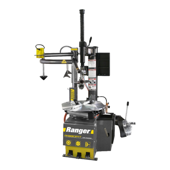
Page 6: Components
Components The following image identifies the main components of the Tire Changer. R980AT shown; the R980XR is not equipped with an Assist Tower, but may be ordered and installed separately. (See Installing the R30XLT Assist Tower in this manual.) Not all components visible. R980 Series of Tire Changers P/N 5900158 —... - Page 7 Tire Changer components include: • Turntable. Holds the Wheel. • RimGuard™ Wheel Clamps. Durable, hardened plastic Clamps do not damage expensive Wheels as they hold the Wheel in place. • Main Tower. Holds the Swing Arm. • Swing Arm. Holds the main tool, the Mount/Demount Head. •...
-
Page 8: Faq
Frequently Asked Questions Question: What does a Tire Changer do? Answer: A Tire Changer takes Tires off of Wheels (called demounting) and puts Tires onto Wheels (called mounting). Q: What is the difference between a Tire, Wheel, and Rim? A: A Wheel is the round metal piece that attaches to the Vehicle’s axle. -
Page 9: Specifications
Specifications Model R980AT R980XR Motor 220 VAC 3 HP, 208-240 VAC, 50-60 HZ, 1 Ph Motor 110 VAC (980AT-L) 2 HP, 110 VAC, 50-60 Hz. 1 Ph. Power Cord Length 96 in (8 feet) / 2,438 mm Drive System Type Electric / Air Air Requirement 140 –... -
Page 10: Installation Checklist
Installation Checklist Following are the steps needed to install the Tire Changer. Perform them in the order shown. ☐ 1. Review the installation Safety Rules. ☐ 2. Make sure you have the necessary Tools. ☐ 3. Find an appropriate Location. ☐... -
Page 11: Installation
⚠ CAUTION Certain parts of installing the Tire Changer are difficult for just one person. BendPak Ranger strongly recommends having two or more persons work together to install the unit. Tools You may need some or all of the following tools: •... - Page 12 A certain amount of space around the Tire Changer is required. above You also need room the Tire Changer. BendPak Ranger recommends leaving at least an above additional 12 inches / 305 mm of open space the highest point of the Tire Changer.
- Page 13 4. Rotate the Cover off and set aside. ⚠ CAUTION Ranger recommends having at least two people lift the Cover off; it is heavy and awkward. If it is dropped or falls, it could cause injury or equipment damage. 5. Remove the Accessory Box.
- Page 14 The Tire Changer has holes for anchoring it into place; anchoring is optional. Note: You are not required to anchor your Tire Changer. BendPak Ranger recommends doing so, as the Tire Changer uses force at various times during the changing of a Tire.
- Page 15 6. Use a torque wrench to tighten each Nut to the torque recommended by the manufacturer of the Anchor Bolt. If no torque is specified, BendPak Ranger recommends ~55 lbf-ft / 74 N-m for a 3/8 in diameter Anchor Bolt. Important: use an impact wrench to torque the Anchor Bolts.
- Page 16 Installing the Tower, Inflation Gauge and the Bead Breaker (R980XR Only) The Tower/Swing Arm, Inflation Gauge and Bead Breaker come uninstalled from the factory. You need to remove them from where they are secured on the shipping pallet and install on the Tire Changer Cabinet.
- Page 17 ⚠ WARNING Use care when moving the Tower; it is heavy and not evenly balanced. If it is dropped, you could injure yourself, bystanders and damage the unit. Make sure to orient the Tower so that the Mount/Demount Head is over the Turntable. 7.
- Page 18 Connecting to Air The Tire Changer requires a 15 to 25 CFM Air Source with an operating air pressure of 140 to 165 PSI (9.6 to 11.4 bar). Important: The Tire Changer uses pneumatic and electrical energy; if your organization has Lockout/Tagout policies, implement them once the unit is connected to the Air Source.
- Page 19 Connecting to Power The R980AT-L Tire Changer must be connected to a 110 VAC power source on a dedicated 20 Amp circuit . The 110 VAC Unit’s power cord is prewired with a plug. The R980AT and R980XR Tire Changers must be connected to a 208-240 VAC power source, on a...
- Page 20 The Tire Changer comes with a Lube Bucket (to hold your Lube) and a Lube Brush (to apply your Tire Lube). BendPak Ranger does not include any Tire Lube with the Tire Changer, as there are many options available. ⚠...
- Page 21 The Tire Changer comes from the factory with the Assist Tower Post already greased. Re-grease the Post as required. BendPak Ranger recommends a lithium-based grease that includes molybdenum and graphite. For example, Extreme Pressure Moly-Graph® Multi-Purpose Grease from CRC/Sat-Lube®. ⚠...
- Page 22 The following procedure details the installation of an optional Assist Tower for the R980XR, providing enhanced functionality to the Tire Changer. The R30XLT may be ordered through bendpak.com/support, or by calling BendPak Ranger at (805) 933-9970. Components The photo above shows the main components of the R30XLT Assist Tower: •...
- Page 23 To install the R30XLT Assist Tower: 1. Unpack the R30XLT Assist Tower, including the Parts Box. ⚠ CAUTION Use care when moving the Assist Tower, it is heavy. 2. Open the Parts Box and remove the five black Bolts. 3 ea. M12 x 25 and 2 ea. M12 x 20. 3.
- Page 24 View is inside of the Tire Changer, with Side Panel removed. Not to scale. Not all components shown. 11. Cut the short Tubing piece in the middle. 12. Take the Tee Connector end of the New Air Hose and connect it at two places where you cut the short Tubing piece, as shown above.
- Page 25 Tower Controls to raise and lower the Tool Arms (they move up and down together). If the Tool Arms can do these things, they are working correctly. • Change some non-customer Tires. To get used to the Tire Changer, BendPak Ranger non-customer Tires recommends have all potential Operators change some before putting the Tire Changer into normal operation.
-
Page 26: Operation
Centering/Inflation Tool, or in a Tire Inflation Cage (such as the RIC-4716 4-Bar Tire Inflation Cage from BendPak Ranger). Do not inflate a Tire if it is externally clamped; external clamping interferes with inflation. • When using the Tire Changer, be careful of your hands; there are multiple pinch point dangers on Do not rest your hands on any part of the Tire Changer while using it the unit. - Page 27 Keep the work area clean and well lit. Dirty, cluttered, and dark work areas increase the chances of an accident happening. • Do not access the inside of the unit unless instructed to do so by BendPak Ranger Support. ⚠ WARNING Be especially careful when inflating Tires.
- Page 28 Turntable The Turntable is where you the Wheel and Tire is clamped to be dismounting or mounting. Top and side views. Not necessarily to scale. Not all components shown. There are several important things to know about the Turntable: • Flat, steel piece.
- Page 29 As a general rule, you clamp steel Wheels internally (Clamps push out against Wheel) and custom and mag Wheels externally (Clamps push in against outside Rim edge). Check with your supervisor if you are unclear about which method to use for a particular set of Wheels. To clamp externally : If necessary, use the Clamps Foot Pedal to move the Clamps all the way (they may be all the way out already), position the Wheel between the Clamps, then press...
- Page 30 Pedals The Tire Changer has four Foot Pedals: • Inflation Foot Pedal. Supplies air through the Air Pressure Gauge Cord. • Turntable Foot Pedal. Rotates the Turntable. Press down to go clockwise, press up to go counter-clockwise. • Clamps Foot Pedal. Moves the Clamp Mechanisms in or out. Press down and release to move the Clamp Mechanisms out (if they are in), press down and release to move the Clamp Mechanisms in (if they are out).
- Page 31 Air Pressure Gauge Shows the air pressure in Tires to which the Air Chuck is attached. The components of the Air Pressure Gauge are: • Gauge. Displays air pressure in the Tire to which the Air Chuck is attached. • Pressure Relief Button.
- Page 32 Swing Arm The Swing Arm holds the main Tire Changer Tool, the Mount/Demount Head. It swings out of the way when you do not need it. Front view. Swing Arm shown fully to the right. Not necessarily to scale. Not all components shown. The main parts of the Swing Arm are: •...
- Page 33 Mount/Demount Heads The Mount/Demount Head is the main tool on the Tire Changer for demounting and mounting Tires. The Tire Changer comes with two Mount/Demount Heads: • Alloy Steel. Lasts virtually forever. Silver in color. Includes plastic inserts on the inside to avoid damaging Rims and a roller for extra mounting functionality.
- Page 34 Bead Breaker Use the Bead Breaker to break the Beads (on both sides) of the Tires you are changing. ⚠ Do not break the Beads of a Tire until you are certain the Tire is fully WARNING deflated . Breaking the Bead of a Tire with air still in it could injure you or others nearby.
- Page 35 • Adjustment Rod. Allows you to accommodate Tires of different sizes by controlling the location of the Bead Breaker Mechanism. When the Adjustment Know is in the locking position, the Bead Breaker Mechanism can come out further, accommodating larger Tire sizes. To use the Adjustment Rod : Grab the end of the rod, then move the outside of the rod from its current locking position to the other locking position.
- Page 36 Assist Tower or the Tools on it. An Assist Tower is available for the R980XR as an option. Order Model Number R30XLT from the BendPak Ranger website , or call (805) 933-9970. The two Assist Tower Arms move up and down as one, but move side to side independently.
- Page 37 Before You Change a Tire ⚠ DANGER Do not use the Tire Changer unless you have been properly trained and have read the entire Installation and Operation Manual. Tire changing must only be done by Failure to understand and follow trained, authorized, supervised personnel.
- Page 38 The Tire, Wheel, or both can be damaged and the Tire could explode under pressure, resulting in serious injury or death. BendPak Ranger recommends you not try to demount or mount this type of Wheel . If you do attempt to demount or mount this type of Wheel, proceed with extreme caution.
- Page 39 The Steps in Changing a Tire Before you start working on a Tire, review the requirements in Before You Change a Tire. Changing a Tire consists of multiple steps: 1. Deflate the Tire. There is a lot of energy stored in a Tire when it is inflated. You must fully deflate the Tire before you can demount it.
- Page 40 Tire on a Wheel. When mounting a new Tire, BendPak Ranger recommends installing a new Valve Stem, but it is not required. The process for replacing a Valve Stem is to cut out or pull out the old Valve Stem, then install the new Valve Stem.
- Page 41 If you are going to use the same Valve Stem with the new Tire you are going to mount, keep the Valve Core you just took out. BendPak Ranger recommends installing a new Valve Stem when you mount a new Tire. 3. Make sure all of the air comes out of the Tire.
- Page 42 Break the Beads The Beads must be broken – on both sides of a Tire – before the Tire can be demounted. ⚠ WARNING Do not Break the Bead of a Tire until have made sure the Tire is fully deflated. A Tire with air still in it could explode, injuring the Operator or bystanders.
- Page 43 9. Step on and hold down the Bead Breaker Foot Pedal. The Blade pushes in, moving the Bead out of the Bead Seat and in towards the Drop Center of the Tire. When the Bead breaks, it frequently (but not always) makes an audible popping sound. 10.
- Page 44 Secure the Wheel on the Turntable Before you can demount a Tire, you must secure the Wheel on the Turntable. The Tire Changer supports two ways of securing the Wheel to the Turntable: • External clamping. The Clamps are on the outside, pressing inwards. •...
- Page 45 Demount the Tire Demounting a Tire is the process of taking a Tire off a Wheel. Specifically, you need to pull the top Bead over the top of the Rim, then pull the bottom Bead also over the top of the Rim. ⚠...
- Page 46 6. Take the Bead Lifting Tool, position one end on the outside of the Demount Lip of the Mount/Demount Head, then slide it down between the Demount Lip and the top Tire Bead until it is just past (and a little under) the Bead. 7.
- Page 47 14. Take the Bead Lifting Tool, put it on the outside of the Demount Lip, then slide it down past and under the bottom Bead. Getting the Bead Lifting Tool into position may be trickier this time, as the rest of the Tire is in the way as you are trying to get access to the bottom Bead.
- Page 48 Mount a New Tire Mounting a Tire is the process of putting a Tire onto a Wheel. ⚠ WARNING Mounting a new Tire can be hazardous if not done correctly. Do not change a Tire unless you have been trained to do so. Failure to understand and follow proper procedures can result in injury or death.
- Page 49 7. Push the side of the Tire furthest away from the Mount/Demount Head down over that side of the Rim and Wheel as far as it will go. 8. Press down on the Turntable Foot Pedal. The Turntable will turn clockwise and the bottom Tire Bead will drop over the top of the Rim. 9.
- Page 50 13. If using the R980AT, position the Assist Tool to the left of the Mount/Demount Head (about 20 percent of the total distance around the Tire), with the Assist Tool pushing down on the Sidewall of the Tire. Top view. Not to scale. When you start rotating the Tire, move the Assist Tool around as the Tire moves around, keeping the Tool at the same spot on the Tire.
- Page 51 Inflate the Tire Tire inflation has three stages: sealing • Bead is putting in a small amount of air pressure to push the Tire up against the Rim so the rest of the air you put in does not leak out. Remove the Valve Core before beginning the Bead sealing, as that allows more air to go in through the Valve Stem.
- Page 52 Bead Sealing To seal a Tire’s Beads, you put a small amount of air pressure into the Tire, which pushes the Tire up against the Rim so that additional air you put in does not leak out. To Seal the Beads: 1.
- Page 53 Bead Seating To seat a Tire’s Beads, you put in additional air pressure until you hear a “pop”, which indicates the Tire Beads have slipped over the Bead Humps into their Bead Seats. Remember that a Tire has Beads on both sides of the Tire. The Beads have to be seated on both sides.
- Page 54 Inflating the Tire To inflate a Tire after sealing and then seating the Beads, add air pressure to the Tire to get the pressure to the manufacturer’s recommended pressure. Use the Pressure Gauge to monitor air pressure; do not ‘guesstimate’ the psi. ⚠...
-
Page 55: Maintenance
• Daily: Make sure the unit is clean and dry. • Weekly: Check all labels to make sure they are in place and legible. Contact BendPak Ranger if replacement labels are needed. • Weekly: Check the water level of the Regulator/Filter. If the reservoir is one quarter (25%) or more filled with water, drain it. - Page 56 Check the Water Level Water coming in from the Air Source is pulled out of the incoming air by the Regulator/Filter and dropped into the reservoir at the bottom. This water needs to be drained periodically. To drain water from the Regulator/Filter reservoir: 1.
- Page 57 Check the Oil Feed Rate and Adding Oil The built-in lubricator adds pneumatic oil to the incoming air. This ensures that all pneumatic components of the Tire Changer receive the necessary lubrication, which maintains operating performance, reduces wear, and extends service life. It is very important to make sure the oil feed rate is correct, 1 or 2 drops of oil per use of pneumatic component (such as the Clamps Foot Pedal), and that there is enough pneumatic oil in the Oil Reservoir of the Oiler/Lubricator.
-
Page 58: Troubleshooting
Grease the Assist Tower Post for more information. noises when moving. If you continue to have problems with your Tire Changer, visit www.bendpak.com/support/ or call BendPak Ranger at (805) 933-9970. R980 Series of Tire Changers P/N 5900158 — Rev. F - March 2022... -
Page 59: Wiring Information
Wiring Information The Tire Changer comes with a Power Cord that is connected inside the unit on one end and with three exposed wires on the other end (called a ‘pigtail’). The three exposed wires need to be hard- wired to the facility’s power system or connected to a 250 VAC, 30A, 2-Pole, 3-Wire, NEMA rated plug (which is then connected to a power outlet). -
Page 60: Labels
Labels R980 Series of Tire Changers P/N 5900158 — Rev. F - March 2022... - Page 61 R980 Series of Tire Changers P/N 5900158 — Rev. F - March 2022...
- Page 62 R980 Series of Tire Changers P/N 5900158 — Rev. F - March 2022...
-
Page 63: Parts
Parts Cabinet Number Part Number Description Container weldment Container weldment 5327673 Side Cover Container front face weldment Socket head cap screw M6 x 16 Large flat head screw with cross groove 5328066 Chassis front board (A) Chassis front board Washer; M6 x 12 mm Flat Socket head cap screw M6 x 12 5400913 Washer;... - Page 64 119-2 5327806 Fitting; 1/4 x 1/4 Tee Fitting G1/4″ φ12 119-3 119-4 Tower straight in G1/4″ -G1/4″ 119-5 5327684 Oiler cup 119-6 5327685 Filter cup 119-7 Air pressure gauge 119-8 5327847 Yellow Air Oiler; I Models Fitting G1/4″ φ12 Straight 119-9 Rubber cord grip 5401121...
- Page 65 Main Tower Number Part Number Description 5601102 Tower unit weldment Washer; M12 x 24 Hexagon headed bolt M12 x 60 Locknut M16 Lock pad 5401222 Swing Arm Adjustment Screw with Knob 5404141 M18 Snap Ring Mount / demount head φ46 x 34 x 12 5327310 5328198 Metal duckhead...
- Page 66 5327619 Vertical Shaft 5400237 Hex Shaft Spring; B & I Models 5400942 Socket head cap screw M10 x 25 Hex shaft cap 5327620 Hex Shaft Lock Cover Socket head cap screw M6 x 30 Hexagon headed bolt M10 x 25 Thin nut M10 5327359 Swing arm pivot pin...
- Page 67 SHCS M8 x 25 5328119 Duckhead Insert (A) 5327880 Plastic components of bird head Quick change head fixed set of bird 5327883 SHCS M8 x 45 SHCS M8 x 40 Plastic bird head flange 5328289 Plastic head flange 5150523 Plastic head of A bird 5545202 Washer;...
- Page 68 5327300 Jaw clamp cylinder 302-1 5327475 Fitting; G1/8 8 mm 302-2 5327365 Small Front Cylinder Cover; I Models 302-3 5327487 O-Ring 25 x 3.1; I Models 302-4 Jaw Clamp Cylinder Wear Strip; I Models 302-5 5401421 HHB M8 302-6 Locknut M8 302-7 Small Cylinder Piston;...
- Page 69 5327405 Jaw Clamp Support; R23/26/980 (I) 5328306 Jaw Clamp Support; R76/980 327-1 Jaw Clamp Support assy 5327630 Jaw Clamp Inner Adjustment Knob 5327621 Jaw Clamp Inner Adjustment Pin 5327662 Jaw Clamp Pin Spring 5327623 Jaw Clamp Locking Pin 5327623 Jaw Clamp Locking Pin 5328328 Boat gasket Turntable assy (B) cylinder bracket assembly...
- Page 70 Cylinder liner Nut M18 x 1.5 - Thin threaded Piston limit bowl 5327682 Y-Ring Ø200 x 12 x 6 mm 5327413 BB Cylinder Piston; I Models 5327537 O-Ring; 193 x 5.7; I Models 5328078 Eccentric Bushing; I Models O-Ring; φ25 x 3.1 5327487 Y-Ring φ25 5327493...
- Page 71 O-Ring φ 25 x 3.1 5327487 Cross recessed round head screw M6 x 10 Cross recessed round head screw M6 x 10 Fitting; G1/4" 12 mm Leather packing Metal quick exhaust valve leather cushion 5327732 Fitting; G1/4" 12 mm Quick exhaust valve Metal quick exhaust valve Quick drain valve bowl Quick exhaust valve metal cup...
- Page 72 Gearing Number Part Number Description 5327479 Gearbox assy 5327479 Gearbox assy 500-1 5327175 Rotary valve assy 500-1 5327175 Rotary valve assy Gearbox front flange 5327520 Hexagon headed bolt Oil plug Washer φ10 Hexagon headed bolt M10 x 180 Socket head cap screw M8 x 30 Large gear key 12 x 8 x 35 Oil block 45 x 8 Cone roller bearing 6205...
- Page 73 Gearbox back flange Nut M10 Washer φ10 Nut M8 Bering 80208 Seeger ring φ50 Helical gear m2 (Al) Spline shaft Bering 6010 Hexagon headed bolt M10 x 170 Fitting G1/8″ φ8 5327745 Fitting; φ8- φ8-G1/8″ 5328350 Fitting G1/8″ φ8 5327745 Inner hexangular set screw M6 x 20 Rotary Joint Block Inner Piece;...
- Page 74 Pedals Number Part Number Description Directional Switch Cover Air valve shaft 601-1 5327531 Tilt tower air valve shaft I Models Washer; φ6 spring Cross recessed round head screw M6 x 12 Cross recessed round head screw M4 x 10 Nut M8 Spring pin M 4 x 18 φ4 x 18 Socket head cap screw M6 x 55 5327482...
- Page 75 Washer; M6 x 12 mm Flat 5400913 Washer; M6 flat Washer φ5 flat Washer φ5 spring Cross recessed round head screw M5 x 16 5400324 Turntable Direction Switch Cam; B & I 5327038 Directional Switch Cam Linkage; I Models Cross recessed round head screw M4 x 16 Washer φ4 spring Washer φ4 flat Washer φ6...
- Page 76 BB cylinder air valve assy BB cylinder air valve assy Cylinder air valve assy Foot pedal assy Turbo Blaster Number Part Number Description 5328443 Locknut elbow Union Turbo blast handle Vent valve Clamp nut White steel buckle Nylon sleeve PVC steel wire tube PU straight pipe Elbow O-ring φ40 ×...
- Page 77 Movable joint sleeve Movable joint 5328494 Outer wire pitch assembly 705-1 O-ring 705-2 Piston 705-3 Spring 705-4 Valve 705-5 Button 1" Connector 1" Connector 730-1 5327892 Turbo Blast Complete – OLD RED HOSE 730-1 5328444 Turbo Blast Complete – NEW CLEAR HOSE Snap Ring φ40 5327611 5327335...
- Page 78 Assist Tower (not included with the R980XR) R980 Series of Tire Changers P/N 5900158 — Rev. F - March 2022...
- Page 79 Number Part Number Description 800-1 5150545 Upgrade Tower 801-1 Assist Arm Valve Control Assy 5327098 L/R Assist Arm Valve Cover; I Models 5530012 Cross recessed round head screw M4 x 0.7 x 30 mm 5327109 Assist Arm Control Valve; I Models Banjo bolt φ6 G1/8"...
- Page 80 Locknut elbow 5327472 Turbo Blast Hook; I Models Nut M8 5328299 Presser arm weldment 839-1 Metal Braided Hose Cover Slide Unit Slide Unit 5327483 Assist Tower Plastic Slide; I Models 5327483 Assist Tower Plastic Slide; I Models Slide Guide Left Assist Tower Weldment 5327434 Assist Tower Top Plug Washer φ10 Splick lock...
- Page 81 Washer φ5 Flat Washer φ5 Splick lock Washer φ12 split lock Cross recessed pan head screw M4 x 12 Bearing B3025 5327979 Assist tower bent arm plug Seal ring φ33 × 2 5× 6 Seal ring φ33 × 25 × 8 SHCS M8 x 30 Washer φ8 Splick lock Washer φ8 Flat...
- Page 82 Number Part Number Description Inflation foot pedal assy 148-1 5327178 Plastic foot pedal cover 148-2 5327670 Inflation foot pedal lever 148-3 Cross recessed round head screw M6 x 12 148-4 Pedal valve unit weldment 148-5 Bead blaster valve assembly O-ring φ15.4 x 3.9 148-5-1 5327821 Air valve end cap φ15 x 1.2...
- Page 83 Assist Tower (Optional) R980 Series of Tire Changers P/N 5900158 — Rev. F - March 2022...
- Page 84 Number Part Number Description Center power hand Quick union M6X1/8″ 90° 5327740 Fitting; Φ6 G1/8″ 90° 801-1 5324168 8mm to 6mm union PU air compressor hoseφ6 5327637 Assist Tower Rear Cyl Plate; R30XLT(3) 5327638 O-Ring Ø84 x 3.1mm; R30XLT (10) 5327639 Assist Cylinder Body Ø75 x 360mm;...
- Page 85 836-1 5327802 Fixed roller assy. (A) 836-2 Assist arm slide roller weldment (A) 836-3 Slide set of components (C 5327654 AT Roller Lock Nylon Insert; R30XLT Club hand shank M12 5327857 AT ROLLER LOCK BOLT;R980/30 839-1 5327655 Assist Tower Roller Lock Knob; R30XLT (4) Washer φ10 flat 5327696 HHB M10X20(LEFT HAND THREAD)
- Page 86 Quick plug bent on φ6-G1/4" 5327740 Banjo bolt 8mm 1/8 φ6 single Washer φ4; flat Cross recessed round head screw M4X30 Adjustment silencer G1/4″ Adjustment silencer G1/8″ 5327545 Assist Arm Control Valve; I Models 5327109 Assist Arm Control Valve; I Models B Cross recessed round head screw M4 Washer φ4 Cross recessed tapping screws M4.2X13...
-
Page 87: Maintenance Log
Maintenance Log R980 Series of Tire Changers P/N 5900158 — Rev. F - March 2022... - Page 88 1645 Lemonwood Drive Santa Paula, CA 93060 USA © 2022 BendPak Inc. All rights reserved. bendpak.com...
Need help?
Do you have a question about the R980AT-L and is the answer not in the manual?
Questions and answers