Table of Contents
Advertisement
Quick Links
Product overview
Table 1 HP MSR 2000, 3000 and 4000 Router Series models
Product code
JG$
JG
$
J*$
JG$
JG$
JG$
J*$
For regulatory identification purposes, the products are assigned Regulatory Model
x
For regulatory identification purposes, the HP 5920AF-24XG and HP 5920AF-24XG TAA products
are assigned Regulatory Model Numbers (RMN). The Regulatory Model Numbers for these
Numbers (RMN). The Regulatory Model Numbers for these products are listed below.
products are listed below. These regulatory numbers should not be confused with the marketing
These regulatory numbers should not be confused with the marketing name (HP description)
names HP 5920AF, or product numbers JG296A and JG555A.
or product numbers (product code).
Product code
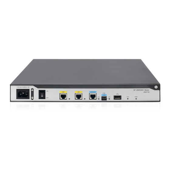
JG411A
JG296A
______________________________________________________________________________________
JG555A
JG409A
x
For
regulatory
______________________________________________________________________________________
5900AF-48XG-4QSFP+ TAA products are assigned Regulatory Model Numbers (RMN). The
JG406A
Regulatory Model Numbers for these products are listed below. These regulatory numbers should
______________________________________________________________________________________
not be confused with the marketing names HP 5900AF, or product numbers JC772A and JG554A.
JG405A
Product code
______________________________________________________________________________________
JG404A
JC772A
______________________________________________________________________________________
JG554A
JG403A
x
______________________________________________________________________________________
For regulatory identification purposes, the HP 5900AF-48XGT-4QSFP+ Switch is assigned a
regulatory model number (RMN) BJNGA-AD0018. This regulatory number should not be confused
JG402A
with the marketing name HP 5900AF, or product code JG336A.
x
For regulatory identification purposes, the HP 5900AF-48G-4XG-2QSFP+ Switch is assigned a
regulatory model number (RMN) BJNGA-AD0017. This regulatory number should not be confused
with the marketing name HP 5900AF, or product code JG510A.
HP description
+3 065 $& 5RXWHU
+3 065 $& 5RXWHU
+P 065 $& 5RXWHU
+3 065 5RXWHU
+3 065 5RXWHU
+3 065 5RXWHU &KDVVLV
+3 065 5RXWHU &KDVVLV
RMN
BJNGA-BB0009
BJNGA-AC0007
BJNGA-AC0007
BJNGA-BB0008
identification
purposes,
BJNGA-BB0007
BJNGA-BB0011
RMN
BJNGA-BB0006
BJNGA-AD0016
BJNGA-AD0016
BJNGA-BB0010
BJNGA-BB0005
1
Alias
HP 065
+3 065
HP 065
+3 065
+3 065
+3 065
+3 065
HP description
HP MSR2003 AC Router
HP 5920AF-24XG Switch
HP 5920AF-24XG TAA Switch
HP MSR3012 AC Router
the
HP
5900AF-48XG-4QSFP+
HP MSR3024 AC Router
HP MSR3044 Router
HP description
HP MSR3064 Router
HP 5900AF-48XG-4QSFP+ Switch
HP 5900AF-48XG-4QSFP+ TAA Switch
HP MSR4060 Router Chassis
HP MSR4080 Router Chassis
and
HP
Advertisement
Table of Contents
Troubleshooting

Related Manuals for HP MSR 2000


Summary of Contents for HP MSR 2000
- Page 1 BJNGA-BB0007 HP MSR3024 AC Router Regulatory Model Numbers for these products are listed below. These regulatory numbers should ______________________________________________________________________________________ not be confused with the marketing names HP 5900AF, or product numbers JC772A and JG554A. JG405A BJNGA-BB0011 HP MSR3044 Router Product code...
-
Page 2: Table Of Contents
Contents Preparing for installation ············································································································································· 1 Safety recommendations ·················································································································································· 1 Safety symbols ·························································································································································· 1 General safety recommendations ··························································································································· 1 Electricity safety ························································································································································ 1 Laser safety ································································································································································ 1 Examining the installation site ········································································································································· 1 Temperature and humidity ·······································································································································... - Page 3 Troubleshooting ······························································································································································i Troubleshooting the power supply system failure ··········································································································· i Troubleshooting fan failures ·············································································································································· i Troubleshooting the configuration system failures ········································································································· ii No display on the configuration terminal ·············································································································· ii Garbled characters on the configuration terminal ································································································ ii ...
-
Page 4: Preparing For Installation
Preparing for installation Safety recommendations Safety symbols When reading this document, note the following symbols: WARNING means an alert that calls attention to important information that if not understood or followed can result in personal injury. CAUTION means an alert that calls attention to important information that if not understood or followed can result in data loss, data corruption, or damage to hardware or software. -
Page 5: Temperature And Humidity
Temperature and humidity You must maintain a proper temperature and humidity in the equipment room. Lasting high relative humidity tends to cause poor insulation, electricity creepage, mechanical property change of materials, and corrosion of metal parts. Lasting low relative humidity is likely to result in loose screws due to washer contraction, and even ... -
Page 6: Esd Prevention
Figure 1 Airflow through the MSR4000 chassis To ensure good ventilation, the following requirements must be met: Leave at least 10 cm (3.94 in) of clearance for the air inlet and outlet vents. The installation site has a good cooling system. ... -
Page 7: Emi
To attach an ESD-preventive wrist strap: Wear the wrist strap on your wrist. Lock the wrist strap tight around your wrist to keep good contact with the skin. Insert the ESD-preventive plug into the ESD-preventive socket. Connect the alligator clip to the rack. All electromagnetic interference (EMI) sources, from outside or inside of the router and application system, adversely affect the router in a conduction pattern of capacitance coupling, inductance coupling, electromagnetic wave radiation, or common impedance (including grounding system) coupling. -
Page 8: Installation Accessories Shipped With The Router
ESD-preventive gloves, ESD-preventive wrist wrap, and antistatic bag or mat Installation accessories shipped with the router Power cord Console cable Grounding cable Mounting brackets Checklist before installation Table 4 Checklist before installation Item Requirements Result ... - Page 9 Item Requirements Result The grounding cable of the chassis is well grounded. The grounding terminal of the AC power receptacle is well grounded. Lightning protection A port lightning arrester is installed. (Optional.) A power lightning arrester is installed. (Optional.) ...
- Page 10 Contents Installing the router ·························································································································································i Installation prerequisites ···················································································································································· i Installation flow ·································································································································································· i Installing the router ··························································································································································· iii Installing an air filter ··············································································································································· iii Mounting the router on a workbench ···················································································································· iv Installing the router in a 19-inch rack ··················································································································· iv ...
-
Page 11: Installing The Router
Keep the tamper-proof seal on a mounting screw on the chassis cover intact, and if you want to open the chassis, contact HP for permission. Otherwise, HP shall not be liable for any consequence. Installation prerequisites You have read "Preparing for installation" carefully. - Page 12 Figure 2 Installation flow Start Install an air filter Mount the router to a Mount the router to a rack workbench Mount to a specific position Mount the router to a 19-inch Examine the workbench rack Ground the router Install an MPU Install an SPU Install a CF card Install an interface module...
-
Page 13: Installing The Router
Installing the router Installing an air filter No air filter is provided with the router. Purchase one yourself. To install an air filter: Face the left side (side of the inlet vents) of the router. Install the upper and lower guide rails of the air filter to the chassis. See Figure Fasten the fastening screws on the guide rails with a Phillips screwdriver. -
Page 14: Mounting The Router On A Workbench
Mounting the router on a workbench IMPORTANT: Ensure good ventilation and 10 cm (3.94 in) of clearance around the chassis for heat dissipation. Avoid placing heavy objects on the router. To mount the router on a workbench: Make sure the workbench is clean, stable, and properly grounded. Place the router on the workbench with the upside up. - Page 15 Figure 7 MSR4080 mounting brackets Installing the router to the rack CAUTION: The mounting brackets and rack shelf can support only the weight of the router. Do not place any object on the router to avoid device damage. To install the router to the rack: Use a front mounting bracket to mark the positions of cage nuts, making sure they are at the same level.
- Page 16 Figure 8 Installing a cage nut Install a rack shelf at the position where the cage nuts are installed.
- Page 17 Figure 9 Installing a rack shelf Attach the front mounting brackets to the chassis and fasten the screws clockwise.
- Page 18 Figure 10 Attaching the front mounting brackets to the MSR4060 viii...
- Page 19 Figure 11 Attaching the front mounting brackets to the MSR4080 Place the router on the rack shelf, and secure the chassis by attaching the front mounting brackets with proper pan head screws to the rack. The specifications of pan head screws must satisfy the installation requirements, and rustproof treatment has been made to their surfaces.
-
Page 20: Grounding The Router
Figure 12 Mounting the router to the rack Grounding the router WARNING! Correctly connecting the router grounding cable is crucial to lightning protection and EMI protection. IMPORTANT: The resistance reading should be smaller than 5 ohms between the chassis and the ground. Grounding the router through the grounding terminal on the rack IMPORTANT: Make sure the rack is properly grounded before grounding the router. - Page 21 Use a Phillips screwdriver to fasten the grounding screws into the grounding screw holes. Remove the grounding screw from the grounding point on the rack. Attach the other end of the grounding cable to the grounding point on the rack, and secure it with a screw.
- Page 22 Grounding the router with a grounding strip If a grounding strip is available at the installation site, use grounding screws to attach the ring terminal of the grounding cable to the grounding strip, and make sure the grounding strip is properly grounded.
-
Page 23: Installing The Mpu-100
Figure 14 Grounding the router with a grounding strip Grounding the router with a grounding conductor buried in the earth ground If the installation site has no grounding strips, but earth ground is available, hammer a 0.5 m (1.64 ft) or longer angle iron or steel tube into the earth ground to serve as a grounding conductor. -
Page 24: Installing An Spu
Installing an SPU MSR4000 routers support SPU- 1 00 and SPU-200. The installation procedures are similar. This section describes installation of an SPU-200 to the MSR4060. To install an SPU: Insert the SPU into the slot along the guide rails, and push the ejector levers inward. Use a Phillips screwdriver to fasten the captive screws to secure the SPU to the router. -
Page 25: Installing An Interface Module
Figure 17 Installing a CF card Installing an interface module An HMIM or MIM interface module can be 1U or 0.5U. This section takes a 0.5U interface module for example. When you install a 1U interface module to an MSR router, remove the filler panels of the target slot and the neighboring slot above. - Page 26 Figure 18 Installing an HMIM Fasten the captive screws on the HMIM to secure it to the router. Installing a MIM IMPORTANT: To install a MIM, install it to the HMIM adapter and then insert it into the HMIM slot. ...
-
Page 27: Installing A Power Module
Figure 20 Installing the MIM to the router Installing a power module IMPORTANT: To install two power modules for redundancy, make sure both power modules are AC input or DC input. Installing an AC/DC power module Face the front of the router and locate the slot to be used. Loosen the captive screws with a Phillips screwdriver to remove the filler panel from the slot. - Page 28 Figure 21 Installing an AC power module Figure 22 Installing a DC power module Installing a PoE power module Face the front of the router and locate the slot to be used. Loosen the captive screws with a Phillips screwdriver to remove the filler panel from the slot. Keep the removed filler panel for future use.
-
Page 29: Connecting The Router To The Network
Figure 23 Removing the filler panel Holding the handle of the power module with one hand and supporting the bottom of the power module with the other hand, insert the power module slowly along the slide rails until it makes close contact with the backplane. - Page 30 Figure 25 Connecting the router to a PC Connecting an optical fiber WARNING! Do not stare into any fiber port when you connect an optical fiber. The laser light emitted from the optical fiber may hurt your eyes. Follow these guidelines when you connect a fiber cable: Never bend or curve a fiber when connecting it.
-
Page 31: Connecting The Power Cord
Figure 26 Connecting an optical fiber Connecting the power cord Connecting an AC power cord Make sure the router is well grounded, and the power switch on the router is in the OFF position. Connect one end of the AC power cord to the AC receptacle on the router, and the other end to the AC power source. - Page 32 Figure 27 Connecting an AC power cord to the router Connecting a DC power cord WARNING! Pay attention to the mark on a power cord to avoid connection errors. To connect DC power cords: Make sure the router is well grounded, and the power switch on the router is in the OFF position. Loosen the captive screws on the power module with a Phillips screwdriver to remove the power module connector.
-
Page 33: Verifying The Installation
Verifying the installation After you complete the installation, verify that: There is enough space for heat dissipation around the router, and the rack or workbench is stable. USB devices and interface modules are properly installed. The router, rack, and power cords are properly grounded. The correct power source is used. - Page 34 To connect a USB cable: Connect the USB port to the PC. Connect the other end to the USB console port of the router. Figure 30 Connecting the USB cable Setting terminal parameters This section uses a PC with Windows XP as an example. To set terminal parameters: Select Start >...
- Page 35 Figure 32 Setting the serial port used by the HyperTerminal connection Set Bits per second to 9600, Data bits to 8, Parity to None, Stop bits to 1, and Flow control to None, and click OK. Figure 33 Setting the serial port parameters Select File >...
-
Page 36: Powering On The Router
Figure 34 HyperTerminal window On the Settings tab, set the emulation to VT100 or Auto detect and click OK. Figure 35 Setting terminal emulation in test Properties dialog box Powering on the router Turn on the switch of the power supply system for the router. xxvi... - Page 37 System is starting... Booting Normal Extend BootWare The Extend BootWare is self-decompressing..Done. **************************************************************************** HP MSR4060 BootWare, Version 1.01 **************************************************************************** Copyright (c) 2004-2012 Hangzhou HP Technologies Co., Ltd. Compiled Date : Sep 25 2012 CPU ID : 0x1 Memory Type : DDR3 SDRAM...
-
Page 38: Configuring Basic Settings For The Router
Configuring basic settings for the router After the router is powered on for the first time, configure the basic settings for the router. For more information, see HP MSR Routers Fundamentals Configuration Guide (V7) and HP MSR Routers Fundamentals Command Reference (V7). - Page 39 Contents Replacement procedure ·················································································································································i Replacing a power module ··············································································································································· i Replacing a fan tray ·························································································································································· i Replacing an SPU ····························································································································································· ii Replacing an MPU ··························································································································································· iii Replacing a VPM ····························································································································································· iii Replacing a memory module ··········································································································································· v ...
-
Page 40: Replacement Procedure
Keep the tamper-proof seal on a mounting screw on the chassis cover intact, and if you want to open the chassis, contact HP for permission. Otherwise, HP shall not be liable for any consequence. Replacing a power module The replacement procedure of an AC power module is the same as a DC power module. This section uses an AC power module as an example. -
Page 41: Replacing An Spu
Use a Phillips screwdriver to loosen the captive screws of the fan tray. Holding the handle of the fan tray with one hand and supporting the bottom of the fan tray with the other hand, gently pull the fan tray out of the slot along the slide rails. Figure 37 Removing a fan tray To install a new fan tray, holding the handle of the fan tray with one hand and supporting the bottom of the fan tray with the other hand, gently push the fan tray into the slot along the slide rails. -
Page 42: Replacing An Mpu
Figure 38 Removing the SPU-200 Replacing an MPU To replace an MPU- 1 00: Use a Phillips screwdriver to loosen the captive screws of the MPU until the spring pressure is released. Pivot the ejector levers of the MPU outward, and gently pull the MPU out of the slot. Install a new MPU. - Page 43 NOTE: Before you replace a VPM, remove the SPU from the chassis. For information about removing an SPU, see "Replacing an SPU." VPM (Voice Processing Module) functions to implement the encryption/decryption, EC and CNG of voices. The following types of VPM modules are available on the MSR4000 routers: 256-channel voice processing module (256-VPM) ...
-
Page 44: Replacing A Memory Module
Figure 42 Removing a VPM Figure 43 Installing a VPM Replacing a memory module NOTE: Before you replace a memory module, remove the MPU from the chassis. For information about removing the MPU, see "Replacing an MPU."... - Page 45 Figure 44 MPU structure (1) Front panel (2) Memory module To replace a memory module: Pull the release latches away from the memory module at both ends so that the memory module springs up from the slot. Holding the non-conductive edge, remove the memory module. Keep the removed memory module for future use.
-
Page 46: Replacing An Air Filter
Figure 46 Installing a memory module Replacing an air filter Use a Phillips screwdriver to completely loosen the captive screws of the air filter. Gently pull the air filter out along the slide rails. Figure 47 Removing an air filter Install a new air filter. -
Page 47: Replacing A Cf Card
Figure 48 Removing slide rails Replacing a CF card CAUTION: Execute the umount cfb0: command before you remove the CF card if the router is powered on. To replace a CF card: Press down the spring clip of the CF card cover and open the cover. Press the CF card eject button of the CF card reader so that the eject button projects from the panel. -
Page 48: Replacing An Hmim
Figure 49 Removing a CF card Replacing an HMIM WARNING! Before replacing an HMIM when the router is powered on, you must execute the remove hmimslot slotnumber command first. Completely loosen the captive screws of the HMIM. Gently pull the HMIM out of the slot along the slide rails. Install a new HMIM. -
Page 49: Replacing A Mim
Replacing a MIM WARNING! slotnumber Before replacing a MIM when the router is powered on, you must execute the remove hmimslot command first. To replace a MIM: Completely loosen the captive screws of the HMIM adapter. Gently pull the MIM and the HMIM adapter out of the slot along the slide rails. Figure 51 Removing a MIM and the HMIM adapter Completely loosen the captive screws of the MIM, loosen and take off the screws securing the MIM to the HMIM adapter, and pull the MIM out of the HMIM adapter along the slide rails. - Page 50 Contents Troubleshooting ······························································································································································i Troubleshooting the power supply system failure ··········································································································· i Troubleshooting fan failures ·············································································································································· i Troubleshooting the configuration system failures ········································································································· ii No display on the configuration terminal ·············································································································· ii Garbled characters on the configuration terminal ································································································ ii ...
-
Page 51: Troubleshooting
Keep the tamper-proof seal on a mounting screw on the chassis cover intact, and if you want to open the chassis, contact HP for permission. Otherwise, HP shall not be liable for any consequence. Troubleshooting the power supply system failure Symptom The router cannot be powered on. -
Page 52: Troubleshooting The Configuration System Failures
Troubleshooting the configuration system failures If the router operates properly after being powered on, the boot information is displayed on the configuration terminal. If the configuration system is faulty, the configuration terminal displays garbled characters or does not display anything. No display on the configuration terminal Symptom After the router is powered on, the console terminal does not display anything. -
Page 53: Solution
Execute the save command after modifying the user password to save the new password. [Sysname] save NOTE: HP recommends that you save the modification as the default configuration file. Troubleshooting interface module, cable, and connection failure Symptom After an interface module is installed and the router is powered on, the LEDs on the interface module panel indicate that the interface module is operating improperly. -
Page 54: Restoring The Factory Settings
Solution Verify that the interface module makes good contact with the rear panel of the router slot. Verify that the router supports the interface module. Verify that the interface module is installed in the specified router slot. Verify that a correct cable is used. Verify that the cable is correctly connected. -
Page 55: Reset Button Usage Guidelines
Reset button usage guidelines An MSR4000 router provides the Reset button. You can use the button to reboot the system or restore the factory settings. Press the Reset button for a short time to reboot the router. Press the Reset button for more than 4 seconds to reboot the router and restore the factory settings. - Page 56 Contents Appendix A Chassis views and technical specifications ····························································································i Chassis views ····································································································································································· i MSR4060 ··································································································································································· i MSR4080 ·································································································································································· ii Appearance of the MPU·················································································································································· iii Appearance of SPUs ························································································································································ iv SPU-100 ··································································································································································· iv SPU-200 ··································································································································································· iv ...
-
Page 57: Appendix A Chassis Views And Technical Specifications
Appendix A Chassis views and technical specifications Chassis views NOTE: The router appearance in this installation guide is for illustration only. MSR4060 Figure 53 Front view of the MSR4060 (1) MPU slot 0 (2) SPU slot (3) MPU slot 1 (4) HMIM slot 6 (5) HMIM slot 4 (6) HMIM slot 2... -
Page 58: Msr4080
Figure 54 Rear view of the MSR4060 (1) Fan tray (2) Grounding terminal (3) Power module slot PWR4 (4) Power module slot PWR2 (5) Power module slot PWR3 (6) Power module slot PWR1 (7) Filler panels of the PoE power module slots MSR4080 Figure 55 Front view of the MSR4080 (1) MPU slot 0... -
Page 59: Appearance Of The Mpu
Figure 56 Rear view of the MSR4080 (1) Fan tray (2) Grounding terminal (3) Power module slot PWR 4 (4) Power module slot PWR 2 (5) Power module slot PWR 3 (6) Power module slot PWR1 (7) Filler panels of the PoE power module slots Appearance of the MPU MPU- 1 00 is required for the MSR4000, which performs protocol processing, low-speed packet forwarding, interface control, and fault detection. -
Page 60: Appearance Of Spus
Appearance of SPUs SPU-100 Figure 58 Rear view of the SPU-100 (1) Captive screw (2) Fiber Ethernet ports SFP0 through SFP3 (3) USB port 1 (4) Copper Ethernet ports GE0 through GE3 (5) USB port 0 SPU-200 Figure 59 Rear view of the SPU-200 (1) Captive screw (2) Fiber Ethernet ports SFP0 through SFP3 (3) USB port 1... -
Page 61: Ac Power Module
Install the PoE power module to PWR1 or PWR3. Before you install the PoE power module, remove the filler panel from the slot. The PoE power module requires AC power input. AC power module Figure 60 AC power module (1) Captive screw (2) Power switch (3) Air outlet vent... -
Page 62: Poe Power Module
PoE power module Figure 62 PoE power module (1) Captive screw (2) Power switch (3) Air outlet vent (4) Power receptacle Technical specifications Table 5 Technical specifications Item MSR4060 MSR4080 MPU slot SPU slot HMIM slot Dimensions (H × W × D), 175.1 ×... - Page 63 Item Specification Rated power 300 W Table 8 PoE power module specifications Item Specification Model PSR750-A Rated input voltage range 100 VAC to 240 VAC @ 50 Hz or 60 Hz Rated power 780 W Table 9 MPU-100 specifications Item Specification Console port AUX port...
- Page 64 Contents Appendix B LEDs ····························································································································································i Panel LEDs ··········································································································································································· i Appearance ······························································································································································· i Description ································································································································································ ii Power module LEDs ·························································································································································· iv Appearance ····························································································································································· iv Description ································································································································································ v viii...
-
Page 65: Appendix B Leds
Appendix B LEDs Panel LEDs Appearance Figure 63 MPU-100 LEDs (1) CF card LED (2) USB console port LED (3) Console port LED (4) System LED (SYS) (5) Power module LED (PWR) (6) PoE power module LED (7) MPU status LED (ACT) (8) Fan LED (FAN) Figure 64 SPU-100 LEDs (1) SFP port LED... -
Page 66: Description
Description Table 11 LED description Location Status Description A CF card is in position and the host has detected the Steady green CF card. The CF card is performing read and write operations. Flashing green Do not remove the CF card at this moment. CF card LED MPU-100 Steady yellow... - Page 67 Location Status Description No SFP link is present. Steady green An SFP link is present. Flashing green Data is being sent or received on the SFP link. SFP port LED The transceiver module has failed to pass the Steady yellow detection on the SFP port or the transceiver module cannot be identified.
-
Page 68: Power Module Leds
Power module LEDs Appearance Figure 66 AC power module LEDs (1) Power input LED (2) Power output LED Figure 67 DC power module LEDs (1) Power input LED (2) Power output LED Figure 68 PoE power module LEDs (1) Power input LED (2) Power output LED... -
Page 69: Description
Description Table 12 LED description Location Status Description No power input or the power input is faulty. AC OK AC power module Steady green The power is input properly. No power output or the power output is faulty. DC OK AC power module Steady green The power is output properly. - Page 70 Contents Appendix C Slot arrangement ···································································································································· 1 ...
-
Page 71: Appendix C Slot Arrangement
Appendix C Slot arrangement Table 13 Slot arrangement Model Slot arrangement MSR4060 MSR4080 MPU slots SPU slots HMIM slots...