
Related Manuals for ARRI ALEXA 35


Summary of Contents for ARRI ALEXA 35
- Page 1 ALEXA 35 ALEXA 35 OPERATING MANUAL OPERATING MANUAL July 4, 2022 (1.0) July 4, 2022 (1.0)
- Page 2 In no event shall ARRI or its subsidiaries be liable for or have a remedy for recovery of any special, direct, indirect, incidental, or consequential damages, including, but not limited to lost profits, lost savings, lost...
- Page 3 The information and intellectual property contained herein is confidential between ARRI and the client and remains the exclusive property of ARRI. If you find any problems in the documentation, please report them to us in writing. ARRI does not warrant that this document is flawless.
-
Page 4: Table Of Contents
Content Content About this Document....................... 5 About this Product......................6 Introduction to the ALEXA 35...................6 Intended Use........................6 Identification........................6 Environmental Conditions....................6 Technical Data........................7 Dimensional Drawings....................10 Scope of Delivery and Warranty..................11 Certifications and Safety Standards (in progress)............11 Safety Instructions......................16... -
Page 5: About This Document
The separate ALEXA 35 User Manual contains more detailed information about the features and functionalities of the camera. Please visit the website www.arri.com to download the ALEXA 35 User Manual and much more information. -
Page 6: About This Product
About this Product Introduction to the ALEXA 35 For over a decade the combination of the ALEV 3 sensor and ARRI Color Science have set the gold standard for digital image quality in the professional motion picture industry with ALEXA and AMIRA cameras. -
Page 7: Technical Data
0-95% RH from -20° C to +45° C / -4° F to +113° F Technical Data Sensor Type Super 35 format ARRI ALEV 4 CMOS sensor with Bayer pattern color filter array Sensor Photosites and Size 4608 x 3164 27.99 x 19.22 mm / 1,102x 0,757"... - Page 8 Rec 709, Rec 2020, Rec 2100 PQ, Rec 2100 HLG, LogC4 Look Control ARRI Textures Custom color look (through ARRI Look File ALF4 or ARRI Look Library) White Balance Manual and auto white balance, adjustable from 2000K to 11000K Color correction adjustable from -16 to +16 CC...
- Page 9 About this Product Wireless Interfaces Built-in WiFi module (IEEE 802.11b/g) Built-in White Radio for ARRI ECS lens and camera remote control Lens Mounts & Adapters ARRI LPL Mount (LBUS) ARRI PL-to-LPL Adapter ARRI PL Mount (LBUS) ARRI PL Mount (Hirose)
-
Page 10: Dimensional Drawings
About this Product Dimensional Drawings Camera body with LPL lens mount. All dimensions in mm. -
Page 11: Scope Of Delivery And Warranty
Certifications and Safety Standards (in progress) Approval Information The ARRI ALEXA 35 is approved for use in Europe (CE), USA (FCC), Uk (UCKA), Kanada (ICES), China (CMIIT), Japan (MIC), Australien (SDoC), Korea (ICC), Thailand (SDoC) and where one of those declarations are accepted. - Page 12 You agree to indemnify, defend, and hold ARRI harmless from any and all claims, damages, losses, liabilities, costs, and expenses (including reasonable fees of attorneys and other professionals) that may arise out of a demand on ARRI in connection with your obligations mentioned above.
- Page 13 Brand Name: ARRI Product Description: Digital Camera System ARRI ALEXA 35 The designated products conform to the specifications of the following United Kingdom regulations: The Electromagnetic Compatibility Regulations 2016 (SI 2016 No. 1091 as amended by SI 2019 No. 696) The Electrical Equipment (Safety) Regulations 2016 (SI 2017 No.
- Page 14 About this Product China ALEXA 35 CMIIT ID: 2021AP13709 Japan WiFi Module 003-170091 ECS Transceiver 020-180030 Module Taiwan WiFi Module pending ECS Transceiver pending Module Australia & New Zealand ALEXA 35 South Korea Certification no: ALEXA 35 R-R-ARg-ALEXA35 Singapore pending...
- Page 15 About this Product Egypt WiFi Module pending ECS Transceiver Module pending South Africa WiFi Module pending ECS Transceiver Module TA-2022/0070...
-
Page 16: Safety Instructions
Safety Instructions Safety Instructions This safety information is in addition to the product specific operating instructions in general and must be strictly observed for safety reasons. Read and understand all safety and operating instructions before you operate or install the system. Retain all safety and operating instructions for future reference. -
Page 17: General Safety Instructions
Do not place the system on an unstable trolley or hand truck, stand, tripod, bracket, table or any other unstable support device. Always place the camera on dedicated support devices. Use only accessories approved by ARRI. The use of accessories not approved by ARRI is at your own risk. Please observe all relevant safety guidelines... - Page 18 Do not place any unauthorized objects on the camera system. Do not hang any unauthorized objects on the camera system. Use only accessories approved by ARRI. The use of accessories not approved by ARRI is at your own risk. Please observe all relevant safety guidelines...
- Page 19 Safety Instructions CAUTION! Hot Surfaces on Recording Media During extended operation, high data rates and/or operation at high ambient temperatures, the recording media in the camera can get hot to the touch and can cause pain or even burns if held for too long directly after removal. Do not handle the recording media for longer than three seconds and remove it quickly but carefully.
- Page 20 Place the protective cap on the lens mount, when no lens is attached to the camera Contact ARRI Service to inspect the camera if undefined spots appear in the image. NOTICE Connection of Onboard Monitor Damage to the SDI driver chip caused by power surge.
-
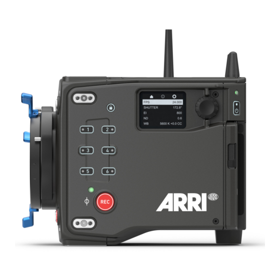
Page 21: Camera Overview
Camera Overview Camera Overview Camera Layout Camera Front SERIAL Connector LBUS Connector (on Lens Mount) VF 1 Viewfinder Connector Lens Mount (here: LPL Mount) LBUS Connector Camera Left Lens Mount (here: LPL Mount) Side Attachment Points LOCK Button Side Display Side Display Jogwheel Rear Camera Status LED Left Camera Status LED... - Page 22 Camera Overview Camera Back Rear Camera Status LED POWER Button Media Door Release Media LED Window Media Door VF 2 Viewfinder Connector SDI 1 Connector SYNC IN Connector SDI 2 / RET IN Connector TC (Timecode) Connector PWR Connector PWR Status LED Camera Rear Interface Camera Top Top Attachment Points...
- Page 23 Camera Overview Media Bay USB-C Connector Recording Media Slot Media Door Media Door Release...
-
Page 24: Multi Viewfinder Mvf-2 Layout
Camera Overview Multi Viewfinder MVF-2 Layout NOTICE Permanent Activation of the Viewfinder OLED Display Permanent activation can cause irreversible burn-ins on the viewfinder OLED display. Do not cover the viewfinder proximity sensor. When covered, the viewfinder OLED display will be switched on permanently. -
Page 25: Mounting And Assembly
When using the system on camera cranes, a suitable safety rope must be used. Use only accessories approved by ARRI. The use of accessories not approved by ARRI is at your own risk. Please observe all relevant safety guidelines. -
Page 26: Power Supply
Mounting and Assembly Bottom Attachment Points The three attachment points on the camera bottom (3, 4) are used to attach the Balance Utility Dovetail BUD-1 (K2.0034180). Use a 3.0 mm Allen/hex key to attach the Balance Utili- ty Dovetail. Tighten screws crosswise. Side Attachment Points The camera is equipped with two accessory attach- ment points (5) each on the camera left and the cam-... - Page 27 Mounting and Assembly Power In (PWR) Connector The PWR 8-pin LEMO connector (1) is located at the right side of the camera. Use KC50-S (K2.75007.0) or KC50-SP- S (K2.0001275) power cables to connect the camera to a power supply. Onboard Battery (BAT) Interface NOTICE Improper Handling of Batteries Risk of damage to the camera system.
-
Page 28: Viewfinder Connection
Mounting and Assembly Power Management When using the PWR connector and an onboard battery adapter simultaneously, the camera’s power management system ensures that the power source with the highest voltage level is used. When the voltage level of one power source drops below the level of the other, or a power source is disconnected from the camera, the power management system automatically switches to the other power source, avoiding shutdown of the camera. -
Page 29: Basic Operation
Switching On the Camera ► Press the POWER button. The camera starts booting. During the boot process, the ARRI logo is shown in the flip-out monitor of the MVF-2 (if connected) and the side display. While the camera is booting up, the POWER button's boot status LED is flashing blue. -
Page 30: Cleaning And Repair
If the sensor cover glass has been contaminated by particles or smear, special optical cleaning kits should be used for dirt removal under very high care. If the contamination cannot be removed, the camera should be taken to an ARRI Service center for cleaning. -
Page 31: Repair
Repairs carried out by Untrained Personnel Risk of electric shock and fire caused by short circuit. Do not try to repair the device yourself. Repairs may only be carried out by authorized ARRI service partners. For repairs and maintenance work on the camera system, please contact "ARRI... -
Page 32: Transportation & Storage
Transportation & Storage Transportation & Storage NOTICE Improper Packing and Transportation of the Camera Risk of damage to the camera system. Follow the specified environmental conditions. Only transport the camera and accessories in suitable cases. Follow the instructions for transport and storage in this chapter. The camera and its accessories can be damaged if not transported and stored properly. -
Page 33: Disposal
Disposal Disposal INFO The product can be returned to the manufacturer. When disposing of accessories, please observe the relevant manufacturer's instructions. This product falls within the scope of Directive 2012/19 / EU OF THE EUROPEAN PARLIAMENT AND OF THE COUNCIL of June 4, 2012 on waste electrical and elec- tronic equipment (WEEE II). -
Page 34: Arri Service Contacts
ARRI Service Contacts ARRI Service Contacts Arnold & Richter Cine Technik ARRI CT Limited / London GmbH & Co. Betriebs KG 2 Highbridge, Oxford Road Herbert-Bayer-Str. 10 UB8 1LX Uxbridge 80807 Munich United Kingdom Germany +44 1895 457 000 +49 89 3809 2121... - Page 35 ARRI Service Contacts CINEOM Broadcast DMCC. CINEOM Broadcast India Pvt. Ltd. Unit No. 2109, Jumeirah Bay Tower X2 Cluster X C-4, Goldline Business Centre Jumeirah Lakes Towers Link Rd. Malad West P.O Box 414659 400 064 Mumbai Dubai, UAE India...
Need help?
Do you have a question about the ALEXA 35 and is the answer not in the manual?
Questions and answers