Table of Contents
Advertisement
Quick Links
-
SHARP
• PRODUCTS OUTLINE
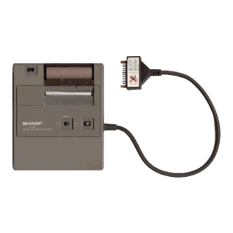
rhe CE-126P prlnter is an optional printer with the cassette
'nterface designed for use with the pocket computer models
?C-17"''', PC-1250, PC-1251, and PC-1401 (El-55OOI.
~.SliECIFICATIONS
'rinter type:
Oot matrix thermal printer (MTP-
201 I, identical to the one used for
the CE-125
'rinting positions:
24 printing positions
'rint speed:
Approx. 0.8 Iines/second
)aper feed speed:
Approx. 0.8 lines/second
~ecording paper:
CPAPR1025CC05 (EA1250P, identi-
cal to the one used for the CE-1251
Thermal recording paper (paper roll
with outer diameter of 18 mm, maxi-
mum, and width of 58mml
~ 'ower supply:
Uses four UM3 (AAl dry celJ batter-
ies.
Options:
AC adaptor (EA-23EI
NiCd battery (EA-27BI
EA-23E for rechargel
'owe......_.,nsumption:
3 watts
3attery Iife:
UM3:
SUM3:
EA-27B:
'hysical dimensions:
140.5(WI x 116(01 x 23(HI mm
3. TAPE RECORDER INTERFACING
METHOD
Tape Recorder,
(use of the
Approx. 2000 lines
Approx. 3000 lines
Approx. 5000 lines
(recharge time: about 15
hours)
CE-l26P
etc.
Pocket computer
PC-12SO, PC-1251,
PC-1251 H, PC-1245,
PC-1401, etc,
SHARP CORPORATION
SERVICE MANUAL
MODEL
G,..,
pi",
tfOfc!llU
=7:!:.~~
I•
Mika it connected
;:t:
<,
!At::'ONE
SPEAKER jock 01
the upe recorder.
• Use of the CE-125 Tape Recorder exclusively design'ed
for the Pocket Computer is recommended.
C-tt.
Tape Recorder
The following
is a descriptlon
cations necessary
Item
1. Recorder
2. Input Jeck
3.
Input Impedance
4. Minimum
5. Output
jack
6. Output
impedance
7. Output
level
8. Distortion
9. Wow and Fluner
10. Other
L...__
Do not sale !
CODE:OOZCE126PSM/E
CE-126P
I ! :'•
I
•
I
of the minimum
tape recorder
for interfacing
with the CE-l26P.
Requirements
Type
Any
tape
recorder,
cassette
or
recorder,
may be used in accor-
dance
with
the requirements
outlined
below.
The
recorder
should
mini-jack input labeled "MIC".
Never use the "AUX"
The input jack should be a low
impedance
input (200 - 1,000
OHM.)
Input level
Below 3 mV or -SO dB.
Should
be a minijack
(EXTernal
"EXT.
"MONITOR",
phone"
or quivalent.
Should be below 10 OHM.
Should
be above 1 V (practical
maximum
outpur
mW)
Should be within 15% within a
range of 2 kHz through
0.3% maximum
Recorder
motor
fluctuate
speed.
-
C E 126P
Grav plug
Ifor datl transfer
.nd .... r ifiation'
Rod
pi",
(tor recording)
specifi-
standard
micro-casserte
have
11
jack.
labeled
speaker",
"EAR
(EAR.
above
100
4 kHz.
(W.R.M.S)
should
not
Advertisement
Table of Contents

Related Manuals for Sharp CE-126P


Summary of Contents for Sharp CE-126P
- Page 1 ;:t: <, !At::'ONE Grav plug Ifor datl transfer SPEAKER jock 01 rhe CE-126P prlnter is an optional printer with the cassette .nd ..r ifiation' the upe recorder. 'nterface designed for use with the pocket computer models pi", (tor recording) ?C-17"''', PC-1250, PC-1251, and PC-1401 (El-55OOI.
-
Page 2: Circuit Description
(1) For DEVICE SELECT, XOUT becomes high. the P-CPU receives a high state of XOUT, it sends The CE-126P has two microprocessors; the P-CPU by which ACK to the M-CPU. data traosfer is carried out with the host CPU (M-CPU) and the M-CPU receives ACK, it sends back BUSY. -
Page 3: Block Diagram
CE 12S-P 5.BLOCK DIAGRAM liREMOTEl lIT ... t2 circuit F.AR Xi" Low battery X01II ~IIIC 1'21 P63 Basy Dout P2I) POIl POl SELI SEL2 DI-4 R/'WIlJSYSEL HI-1 Zero- Driver I. C Crass HI-1 6.CPU(UPD7506G515 PRINTER SIGNAL DESCRIPTI Pin No. Signal Name Description ln/Out SEL2... - Page 4 C E 126P 7. PCU (SC6994) SIGNAL DESCRIPTION Pin No. Signal Name In/Out Oescription SEL2 Select SEL1 Select Power supply Not used BUSY Hi!tl: chip select - - - - - - • - - low: Non-select High to low transition: write Hi!tl: read 7-10 04-1...
-
Page 5: Service Cautions
C E 126P 8. SERVICE CAUTIONS 8-1. Cautions in exchanging the printer unit After the above procedure, adjust by me ans of the 20- Inorder to prevent print density variation caused Kohms protentiometer so that an optimum print quality is thermal head resistance variation, the printhead is classified obtained. - Page 6 C E 126P 9. PARTS SIGNALS POSITION & ...--------------------------------------00 P WB (Top and bottl Chip dl ..DAN202 AC I.PI PWB (Top view) A18U x4 C.Ir 470Knt BE" 58Kn ":r~ · C •• C '.. Q Do not sale !
- Page 7 > :rn vievv tom .Iew) I'O~'I l " 1-- - - - - - - I Printer INd wir. --=,. POWER SW · .:,/' " /- ."_- ~U· ~ ~ • __./ -=l:c:~ " ../ "'4)~ ~!!!.! cl': "r..- ~"...
-
Page 8: Circuit Diagram
CIRCUIT DIAGRAM UXZ,..-l)l- ;;.. 2ZKn Trltt'(ZSCI_ 21111<RVR ..All .. _ ..ZSCIC8I 2llKAVR ;llIn Illn 100Kft ,lOH ZSC2811 Priala' 1Iad-..ICIIKn "NlectiCII 47ft 470 Kn"2 (PCU) 10Kft 5C6994 - --'-+-------, "'ICIIPP "" leodKEY - - - - -- -+--t r-l-+-I- REIIOTI! S. - Page 9 CE 1261' M51Zl1L r--- Tr:i a, 1..-1 ~'."9." ~Rewtl r---..., H COIOlON llad ---+ ~! : 11~:5 L ___ Printer IITP20I-Z41lA IIGEIN Ni--cd --1_-- __ -, !:alte" : ---.., ~_S. ,...-----. t>I LI"I .._ -""" •• lipiD _tor cable IIfTOU1'I ~l!j(SIIJ bh.,>...
-
Page 10: Parts List
C E126P 11. PARTS LIST GUIDE & (*.IU.~~) Exteriors PIlICE RANK PAIIT PARTS CODE DESCRIPTION MARK RAHIl '11",: 1 GCOVA1363CCZZ ..:.,.t Paper cover 'IJ~,' 2 PCUT 102SCCZZ Paper cutter ..:, ,-t 3 GCABB2761CCZZ TODcabinet "''I"t''''.x. 4 JKNBZ122SCCOI + SW "'7:: Silde switch knob ~.f -, S QCNTMI042CCZZ... - Page 11 PARTS CODE 0 E S C R I P T ION PRICE RANK PART Ex MARKRANK 44 RC-CZI052CCNl :1:'-7':.-"'- Capacitor(lSOpF) 45 RH-OZI008CCNl '>('1'-1'71..-{ Diodearray(DAN202) RH-iXI004CCNl Transistor {AI 036) ~7:.-:;~1- 47 RH-iXI009CCNl Transistor(BSISB6B7l ~7:'-:;~1- RH-iXI010CCNI Transistor (All ~7:.-;;~1- 79 M6) 49 RH i X I 0 I 2 C C N 1 Transistor (C2812,L5 l6) 7:'- :;...
- Page 12 SHARP SHARP CORPORA TlON I ndustrial Instruments Group Reliability & Quality Control Departme Yamatokorivama, Nara 639-11, Japan 1983 Ocrober Printed in Japan Do not sale !