Table of Contents
Advertisement
E Schaudt GmbH, Elektrotechnik und Apparatebau, Daimlerstraße 5, 88677 Markdorf, Germany, Tel. +49 7544 9577-0, Fax +49 7544 9577-29, www.schaudt- -gmbh.de
830.588 BA / EN
Instruction manual
Control and Switch Panel DT 220 B
Table of contents
1
. . . . . . . . . . . . . . . . . . . . . . . . . . . . . . . . . . . . . . . . . . . .
2
2.1
2.2
3
4
. . . . . . . . . . . . . . . . . . . . . . . . . . . . . . . . . . . . . . . . . . . . . . . .
5
. . . . . . . . . . . . . . . . . . . . . . . . . . . . . . . . . . . . . . . . . . . . . .
5.1
5.2
5.3
5.4
5.5
5.6
5.7
5.8
6
. . . . . . . . . . . . . . . . . . . . . . . . . . . . . . . . . . . . . . . . . . . . . .
. . . . . . . . . . . . . . . . . . . . . . . . . . . . . . . . . . . . . .
. . . . . . . . . . . . . . . . . . . . . . . . . .
. . . . . . . . . . . . . . . . . . . . . . . . . . . . . . .
. . . . . . . . . . . . . . . . . . . . . . . . . . . . . . . . .
. . . . . . . . . . . . . . . . . . . . . . . . . . . . . . . . . . . . . .
. . . . . . . . . . . . . . . . . . . . . . . . . . . . . . . . . . . . . . . .
. . . . . . . . . . . . . . . . . . . . . . . . .
. . . . . . . . . . . . . . . . . . . . . . . . . . . . . . . . . . . . . . . . . . .
. . . . . . . . . . . . . . . . . . . . . . . . . . . . . . . . . . . . . . . . .
. . . . . . . . . . . . . . . . . . . . . . . . . . . .
. . . . . . . . . . . . . . . . . . . . . . . . . . . . . . . . . . . . . . . . . . .
. . . . . . . . . . . . . . . . . . . . . . . . . . . . . . . .
. . . . . . . . . . . . . . . . . . . . . . . . . . . . . . . . . . . . . . . . . . .
2
2
2
2
3
5
5
5
6
9
10
15
21
25
25
26
27
Issued: 30.06.2006
Advertisement
Table of Contents

Related Manuals for Schaudt DT 220 B


Summary of Contents for Schaudt DT 220 B
-
Page 1: Table Of Contents
..........E Schaudt GmbH, Elektrotechnik und Apparatebau, Daimlerstraße 5, 88677 Markdorf, Germany, Tel. +49 7544 9577-0, Fax +49 7544 9577-29, www.schaudt- -gmbh.de 830.588 BA / EN... -
Page 2: Introduction
Introduction This instruction manual contains important information for the safe operation of equipment supplied by Schaudt. It is imperative that you read and follow this safety information. The instruction manual should always be kept in the vehicle. All safety infor- mation must be passed on to other users. -
Page 3: Application And Function
Only use original fuses rated as specified on the device. Application and function The DT 220 B control and switch panel is the central operating unit for the EBL ... Electrobloc, which supplies all of the 12 V electrical supply’s consu- mers onboard the motorhome or caravan. - Page 4 Truma Triomatict or Truma Duomatic L Plust Internal or external temperature sensors The DT 220 B control and switch panel is responsible for controlling the electrical functions in the motorhome’s living area and displaying various measured values.
-
Page 5: Design
Menu buttons Operation Operating controls The DT 220 B control and switch panel has the following controls fitted to it: Main switch: Button for switching the 12 V supply in the motorhome or caravan on or off. Menu button: Main menu... -
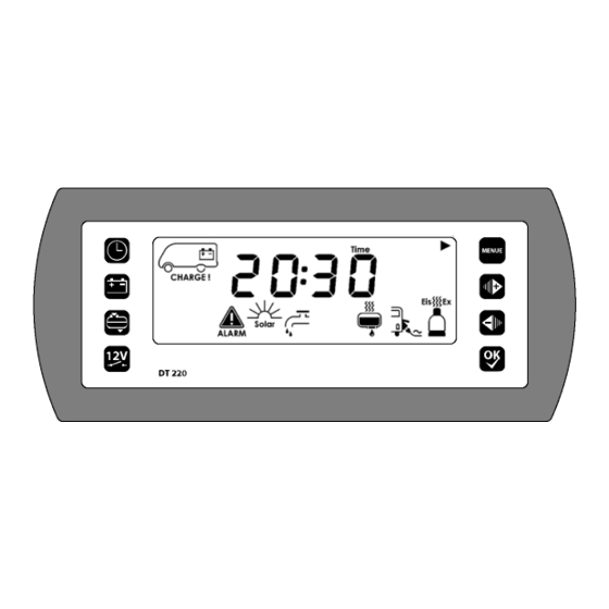
Page 6: Display Controls
DT 220 B control and switch panel instruction manual Display controls The various sections of the display are sub-divided as follows: Fig. 3 Display design (see Chapter 5.3 for segment test display) Main display Info line Unit window Continue arrows... - Page 7 DT 220 B control and switch panel instruction manual Main menu and settings in main menu Press for at least 3 s Fig. 4 Main menu - - menu structure This window is only displayed when the “Truma Duomatic L Plus” or “Truma Triomatic”...
- Page 8 DT 220 B control and switch panel instruction manual Battery menu and settings in battery menu Press for at least 3 s ***** **** **** Fig. 5 Battery menu - - menu structure Setting can be adjusted using the “+” and “- -” buttons; press “OKn” to confirm...
-
Page 9: Reactivation (Following Shutdown)
DT 220 B control and switch panel instruction manual Tank menu and settings in tank menu Press for at least 3 s Fig. 6 Tank menu - - menu structure Only displayed when the “Extra tank” option is active Only displayed when the “Water tap” function is active... -
Page 10: Switching On
DT 220 B control and switch panel instruction manual 230 V mains operation Plug in the 230 V main supply. The “Mains indicator” symbol will be displayed. The batteries will then be charged. Connecting up the battery for the first time: The display will illuminate for approx. - Page 11 DT 220 B control and switch panel instruction manual 5.4.1 Switching on the 12 V supply to the living area The control and switch panel should only be switched on if the leisure battery voltage lies above 11.0 V; otherwise the voltage display (e.g.
- Page 12 DT 220 B control and switch panel instruction manual Use the “+” or “--” buttons to set the year. Confirm the entry by pressing “OK”. Press the “Set up” menu button. The day display flashes. Use the “+” or “--” buttons to set the day.
- Page 13 The ”water pump” symbol is displayed /disappears The power supply for the water pump is switched on/off. When the control and switch panel DT 220 B is in this mode, the ”OK” button is used to switch the current setting.
- Page 14 The ”tank heating” symbol is displayed /disappears. The power supply for the tank heating is switched on/off. When the control and switch panel DT 220 B is in this mode, the ”OK” button is used to switch the current setting.
-
Page 15: Display Menus
DT 220 B control and switch panel instruction manual 5.4.2.6 Switching EisEx-facility on and off This function is only available if a Truma Duomatic L Plus or Truma Trio- matic is fitted in the vehicle. Press the ”Main menu” button. - Page 16 DT 220 B control and switch panel instruction manual 5.5.2 Battery menu Press the “Battery menu” button. The display will illuminate. The remaining utilisable leisure battery capacity will now be displayed. Press the “Battery menu” button several times again (provided that the display is still lit).
- Page 17 DT 220 B control and switch panel instruction manual 5.5.2.2 Battery voltage Battery status The following table shows how to interpret the displayed leisure battery vol- tage correctly. These values apply to actual operation, not off-load voltage. Battery voltage Description 10.4 V or less...
- Page 18 DT 220 B control and switch panel instruction manual The following table shows how to interpret the displayed off-load voltage correctly. These values apply for gel batteries. Values for off-load voltage Charging condition of the battery Less than 12 V Totally discharged 12.2 V...
- Page 19 5.5.2.4 Solar current The solar current display is only available if a Schaudt GmbH LRS ... solar charger is fitted and the “Read solar current” option is active. Solar charging current will be displayed when it rises above 200 mA. The “Sun”...
- Page 20 DT 220 B control and switch panel instruction manual 5.5.3 Tank menu Press the “Tank menu” button. The display will illuminate. The water tank filling level is now displayed. Press the “Tank menu” button several times again (provided that the dis- play is still lit).
-
Page 21: Troubleshooting And Remedies
DT 220 B control and switch panel instruction manual Troubleshooting and remedies 5.6.1 Alarms A flashing warning triangle indicates an alarm in the main menu. A flashing symbol is displayed in the relevant function area in the main menu and the display is also illuminated for 20 seconds whenever an alarm is set. - Page 22 DT 220 B control and switch panel instruction manual Alarm Possible cause Remedy Battery menu: Unknown battery capacity: Use the 230 V power Battery capacity is un- supply to fully charge the known (e.g. after starting battery. This will define the the system up or having charge status.
- Page 23 DT 220 B control and switch panel instruction manual Alarm Possible cause Remedy Acoustic warning (pulsed) Step extended when Retract the step. engine is running. Main menu: Operating fault (false Only occur with an operat- alarm) caused by defec- ing fault: tive sensor or D+ signal is Press “Main menu“...
- Page 24 In this case you must ensure that the warranty is not invalidated by incorrect repairs being carried out and Schaudt GmbH will not accept any liability for damage resulting from such repairs.
-
Page 25: Switching Off
DT 220 B control and switch panel instruction manual Switching off 12 V power supply must always be switched off when leaving the motor- home. This prevents the leisure battery from discharging unnecessarily. Press the “12 V” button briefly. The display will illuminate. -
Page 26: Maintenance
Tank sensors/ Clean the sensors/probes (the sensor/probe surfaces must always be tank probes clean). Inform Schaudt GmbH customer service department if a problem still exists. The reproduction, translation and duplication of this manual, even in parts, is not allowed without written authorisation. -
Page 27: Appendix
DT 220 B control and switch panel instruction manual Appendix EU Conformity Declaration Schaudt GmbH hereby confirms that the DT 220 B control and switch panel design complies with the following relevant regulations: Directive on electromagnetic compatibility 72/245/EEC with 95/54/EC Appendix 1... - Page 28 There are components fitted on the control and switch panel PCB that can be destroyed by an electrostatic discharge (ESD). Do not touch the components fitted on the PCB. A suitable bag can be ordered from Schaudt GmbH if you do not have one available.
- Page 29 DT 220 B control and switch panel instruction manual Fault report In the event of damage, please return the defective device together with the completed fault report. Device type: _______________________ Article no.: _______________________ SW vers.: _______________________ (see Chapter 5.6.3) Vehicle:...
- Page 30 DT 220 B control and switch panel instruction manual Block circuit diagram/Connection diagram Fig. 7 DT 220 B control and switch panel connection diagram X1 Lumberg MSFQ 10-way X6 Lumberg MSFQ 8-way Full Pump Tank heating Frost protection valve n.c.
Need help?
Do you have a question about the DT 220 B and is the answer not in the manual?
Questions and answers