
Related Manuals for PMT EVO 2.0 S

Summary of Contents for PMT EVO 2.0 S
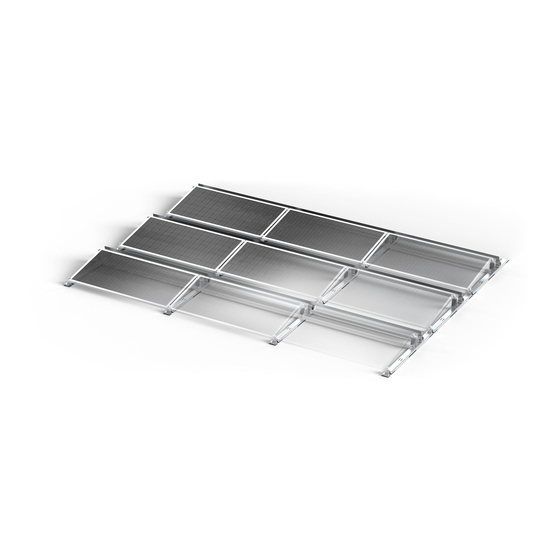
- Page 1 EVO 2.0 S A S S E M B LY I N S T R U C T I O N S O N LY F I V E S T E P S T O T H E C O M P L E T E S Y S T E M...
-
Page 2: General Safety Instructions
Otherwise the instructions must be complied with. roof cladding may be damaged. In the event of noncompliance, PMT reserves the right to • In the event of non-compliance with our general safety instructions or assembly instructions exclude liability. - Page 3 Components Edge profile Cross and ballast strut, Screw M8 x 30 Main profile Cross strut connector Base Ballast stone Tower Middle and end clamp Back wall, Back wall Tower Screw M8 x 16 PMT EVO 2.0 S...
-
Page 4: Required Tools
Required Tools Tape measure Chalk line Torque wrench with attachment Distance gauge SW 5 mm allen key socket PMT EVO 2.0 S... - Page 5 Set up the rows of main profiles with the spacing specified in the planning documents. Use the supplied spacing gauge between the insides of the main profiles. Adjustment: Module length – 95 mm CLICK! Attention! Check the latching connection for proper fitting. PMT EVO 2.0 S...
- Page 6 Place and mount Tower and back wall Tower CLICK! CORRECT! CLICK! INCORRECT! PMT EVO 2.0 S...
- Page 7 Secure cross and ballast strut to cross strut connector Minimum 15 mm M8x30 10 Nm PMT EVO 2.0 S...
- Page 8 Ballast stones on the double cross struts: Mount cross - and ballast struts as described in Step 3 on both tower sides. Place the stones evenly distributed on the the braces. PMT EVO 2.0 S...
- Page 9 Assembly on the Tower CORRECT! Mount middle and end clamps screw on the modules 10 Nm INCORRECT! Middle clamp Minimum 20 mm 10 Nm Assembly on the Base End clamp CORRECT! KLICK! INCORRECT! PMT EVO 2.0 S...
- Page 10 Fit back wall onto back wall tower and screw it on Minimum 40 mm Minimum 20 mm M8x16 10 Nm DONE! PMT EVO 2.0 S...
-
Page 11: Service Hotline
Service-Hotline +49 9225 9550 0 We are happy to advise you. Premium Mounting Technologies GmbH & Co. KG Industriestr. 25 D-95346 Stadtsteinach T +49 9225 9550 0 F +49 9225 9550 999 info@pmt.solutions www.pmt.solutions...
Need help?
Do you have a question about the EVO 2.0 S and is the answer not in the manual?
Questions and answers