Table of Contents
Advertisement
Advertisement
Table of Contents

Related Manuals for FRC PumpBoss PBA100


Summary of Contents for FRC PumpBoss PBA100
- Page 1 PBA100 Rev0407 Document Number: XE-PBA1PM-R0A PRESSURE GOVERNOR with DISPLAY and MONITORING SYSTEM MODEL: PBA100 FIRE RESEARCH CORPORATION www.fireresearch.com 26 Southern Blvd., Nesconset, NY11767 TEL ( 631 ) 724-8888 FAX ( 631 ) 360-9727 TOLL FREE 1-800-645-0074...
-
Page 2: Table Of Contents
PBA100 Rev0407 CONTENTS Table of Contents CONTENTS ........................ 2 INTRODUCTION ...................... 4 Overview ........................ 4 Features ........................4 Specifications ......................5 GENERAL DESCRIPTION ..................6 Controls and Indicators ..................8 INSTALLATION ...................... 10 Install Control Module ..................10 Install Pressure Sensor ..................12 Install Engine Sensors .................. - Page 3 PBA100 Rev0407 List of Tables Table 1. Pressure Sensor Output Voltage ..............5 Table 2. Error Codes ....................15 Table 3. Fault Warning Codes .................. 15 List of Figures Figure 1. Controls and Indicators ................9 Figure 2. Control Module Mounting Dimensions............ 11 Figure 3.
-
Page 4: Introduction
PBA100 Rev0407 INTRODUCTION Overview The Fire Research PumpBoss pressure governor uses state of the art programmable microprocessor technology and operates in one of two modes, pressure or RPM. It will maintain a steady pump discharge pressure within system capabilities by controlling the engine speed. -
Page 5: Specifications
PBA100 Rev0407 Specifications The PumpBoss is available in various models. Each model is programmed to interface with specific engines. All models provide the same functions, controls, and digital readouts for the management of pump discharge pressure. Display Module Supply Power: 12/24 VDC Supply Current: 0.5 Amps... -
Page 6: General Description
PBA100 Rev0407 GENERAL DESCRIPTION The PumpBoss pressure governors are compatible with the following engines: PBA101 Cummins IS Series PBA102 Detroit Diesel PBA104 Navistar PBA105 Caterpillar PBA106* Ford PBA108 Scania PBA109* PBA110 Mercedes * Note: An adapter and cable assembly replaces the basic 8-pin cable when connecting the PumpBoss to a Ford or GMAC engine. - Page 7 PBA100 Rev0407 Pressure Sensor The pressure sensor is mounted on the pump discharge manifold. It provides an input signal to the control module that is proportional to the discharge pressure. Engine Coolant Temperature Sensor The engine coolant temperature sensor is installed as necessary. Engine Oil Pressure Sensor The oil pressure sensor is installed as necessary.
-
Page 8: Controls And Indicators
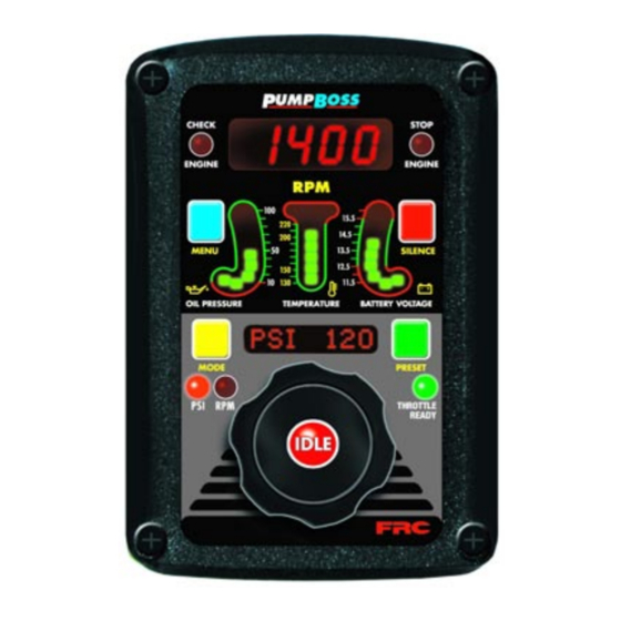
PBA100 Rev0407 Controls and Indicators All controls and indicators are located on the front of the control module. (Refer to Figure 1.) See Operation and Programming Sections for more information. OIL PRESSURE LED Display Shows engine oil pressure. The LEDs will be green when the pressure is within normal limits and red when it is not. -
Page 9: Figure 1. Controls And Indicators
PBA100 Rev0407 Control Knob When rotated changes the pressure or RPM setting. The setting will increase or decrease proportionally to the speed and direction the control knob is rotated. RPM LED The LED is on to indicate operation in the RPM mode. PSI LED The LED is on to indicate operation in the PSI mode. -
Page 10: Installation
PBA100 Rev0407 INSTALLATION Install Control Module 1. Measure and mark mounting location for control module panel cutout and mounting screw holes. Make sure there is clearance behind the panel for the module and cables before cutting holes. Refer to Figure 2 for layout and dimensions. -
Page 11: Figure 2. Control Module Mounting Dimensions
PBA100 Rev0407 4" Mounting holes are 3 1/2" clearance or tapped for 10-32 screws. Panel 5 3/4" Cutout Maximum Radius 1/2" 5 3/4" 1 3/4" 4 5/8" 6 3/4" Figure 2. Control Module Mounting Dimensions... -
Page 12: Install Pressure Sensor
PBA100 Rev0407 Install Pressure Sensor The discharge pressure sensor is mounted on the discharge manifold of the pump. If there is a check valve in the discharge side of the pump, mount the discharge sensor before the check valve. T-fittings can be used to mount the pressure sensors. Note: Install the pressure sensor upright so that the water in the end of the sensor is able to drain back into the pipe. -
Page 13: Install Engine Sensors
Pin 6 on the 12-pin connector at the rear of the control module is provided to connect an optional buzzer. Connect the ground side of the buzzer to pin 6. Maximum current through pin 6 is 300 mA. The buzzer ordered from FRC requires a 1-1/8 inch diameter mounting hole. (Refer to the Wiring section.) -
Page 14: Operation
PBA100 Rev0407 OPERATION On power-up the PumpBoss will be in the pressure mode of operating. The RPM display will show engine at idle RPM, the three LED bar graphs will be green indicating readings within normal ranges, and the message display will alternate between showing the date and time. -
Page 15: Table 2. Error Codes
PBA100 Rev0407 Table 2. Error Codes Message Probable Cause Display Display NO DATA >Datalink cable not connected / connected to wrong port >Broken wire / bad connector contact on datalink cable NO RESP >No responce to control signal NO RPM >Datalink cable not connected / connected to wrong port >Engine not running / ignition key on >Broken wire / bad connector contact on alternator cable... -
Page 16: Pressure Mode Operation
PBA100 Rev0407 Pressure Mode Operation In the pressure mode of operation the PSI LED will be on. The PumpBoss will maintain a constant discharge pressure within system capabilities. It will adjust the engine RPM automatically to compensate for variations in pressure. Note: When changing from RPM mode to pressure mode the pressure setting will be the pressure that the pump was operating at in RPM mode. - Page 17 PBA100 Rev0407 Running Away From Water, No or Low Supply Water There are situations during pump operations when there may be no or low supply water. This can be due to an empty water tank, a problem on the intake line, or when switching the water supply source.
-
Page 18: Rpm Mode Operation
PBA100 Rev0407 RPM Mode Operation In the RPM mode of operation the RPM LED will be on. The PumpBoss will maintain a constant engine RPM. The pump discharge pressure can vary but, as a safety feature, the PumpBoss limits the increase in pressure to 30 PSI over the last established PSI value. As the discharge pressure approaches this limit the PumpBoss will automatically lower the RPM to prevent a high pressure surge. -
Page 19: Switching Between Operating Modes
PBA100 Rev0407 Switching Between Operating Modes • No variation in discharge pressure or RPM will occur when changing between pressure and RPM modes. • When changing to RPM mode, the RPM setting will be the RPM that the pump was operating at in pressure mode. •... -
Page 20: Preset Settings (Pressure Or Rpm)
PBA100 Rev0407 Preset Settings (Pressure or RPM) The preset button allows the operator to go to a pre-programmed pressure or RPM setting during operations. The setting will be shown in the message display. This procedure is to change the setting in the program. Note: The engine must be running and the pump engaged interlock circuit must be closed (the THROTTLE READY LED must be on). -
Page 21: Display Stored Data
PBA100 Rev0407 Display Stored Data Both the RPM and the message displays are used to show stored data. Accumulated Hours and Transmission Temperature Accumulated hours are stored in memory for engine operation, pump operation, last incident, and current incident. The menu button allows the operator to gain access to this stored data. -
Page 22: Programming
PBA100 Rev0407 PROGRAMMING To gain access to the program features a four digit program code must be entered. Review the Program Code Descriptions for the proper four digit code. Both the MENU and SILENCE buttons are used to enter a program code. The RPM display is used to show the codes. -
Page 23: Program Code Descriptions
PBA100 Rev0407 Program Code Descriptions When a valid four digit program code has been entered, stored data or program options will show in the displays. The MENU and SILENCE buttons are used to change the data. The SILENCE button will select the digit that is to be changed. The MENU button will change the digit or change the option choice. -
Page 24: Wiring
PBA100 Rev0407 WIRING The following figures include the schematics, wiring diagrams, block diagrams, and cables for the PumpBoss series governors. Connectors and Cables For most engines the PumpBoss receives engine RPM, oil pressure, and coolant temperature data over the J1939 data link from the ECM. Some engines do not broadcast this data over the data link and sensors may need to be installed. -
Page 25: Figure 5. Pba 8-Pin Connector Wiring
PBA100 Rev0407 8-Pin 12-Pin Connector Control Module Connector Pin 1 Rear View Pin 1 Vent 12/24 Ignition Key 8-Pin Cable + VDC Pump Engaged 8-Pin Interlock Deutsch Connector Butt Connectors 8 Pin Connector/Cable Wire Color Description Supply Voltage (12/24 VDC) Black Ground Orange... -
Page 26: Pressure Sensor
PBA100 Rev0407 Pressure Sensor Pressure Sensor (Top View) Supply Pressure SensorCable Voltage Signal from 12-Pin Connector Output Ground Pressure Sensor Cable 3-Pin Connector Pin/Wire Description A/Black Ground B/Red Supply Voltage C/White Signal Pressure Sensor Side View Vent Port Figure 6. Pressure Sensor Wiring... -
Page 27: Common Oem Diagnostic Connector
PBA100 Rev0407 Common OEM Diagnostic Connector Typical 9-pin Deutsch Diagnostic Connector. Commonly found under the driver side dashboard. 9-Pin Connector Description BATTERY GROUND +12 VDC J1939 DATA LINK (+) J1939 DATA LINK (–) J1939 SHIELD J1587 DATA LINK (+) J1587 DATA LINK (–) PLUG FRONT PLUG... -
Page 28: Cummins Harness Connections
PBA100 Rev0407 Cummins Harness Connections Interface Information For use on 2004 or newer engines. The PUMP BOSS governor is designed to control engine throttle directly over the SAE J1939 databus. If the PUMPBOSS is being used on a COMMERCIAL CHASSIS with a Cummins Engine, ENSURE that the Cummins Engine EMERGENCY VEHICLE CALIBRATION is programmed in the engine ECM for the PUMP BOSS to work. -
Page 29: Detroit Diesel Harness Connections
PBA100 Rev0407 Detroit Diesel Harness Connections Interface Information. Note: Refer to Figure 5. PBA 8-Pin Connector Wiring for power and interlock connections. For DDEC VI 2007 and newer engines. ® DDEC 2/16 Black Wire J1939 CAN (–) 12-Pin Connector 2/17 J1939 SHIELD (Refer to Figure 4) -
Page 30: Navistar Harness Connections
PBA100 Rev0407 Navistar Harness Connections Interface Information The ECM must be programmed for a remote throttle input. Set PTO REMOTE PEDAL to 1. (This will enable the remote throttle input.) The VARIABLE PTO ENABLE input has to be at +12 VDC to activate the remote throttle. -
Page 31: Caterpillar Harness Connections
PBA100 Rev0407 Caterpillar Harness Connections Interface Information The ECM Remote Throttle Option has to be enabled. Refer to an authorized dealer to program this option. 3116B, 3126B, 3176B, 3406E, C7,C9,C10,C11,C12,C13,C15 Engine Interface Engines with 70-pin OEM connector. Note: Refer to Figure 5. PBA 8-Pin Connector Wiring for power and interlock wire connections. -
Page 32: Ford Harness Connections
Foot Throttle 3011 BK/OR yellow/green Signal Return RPM Signal Levels IDLE Note: For wiring on earlier engines Position Sensor #1 4.00V 0.60V contact FRC Engineering. Position Sensor #2 1.42V 4.12V Position Sensor #3 0.88V 3.53V Figure 12. Ford PBA106-B Wiring... -
Page 33: Ford Torque Lock-Up Module
An output from pin 7 (green wire) on the adapter assembly will contol the Torque Lock-up Module The RPM for the green wire to go low and engage the third gear lock-up is factory set. If this setting needs to be changed, contact FRC. From Adapter Assembly 8-Pin... -
Page 34: Scania Harness Connections
PBA100 Rev0407 Scania Harness Connections Interface Information For use on P, R, and T-series trucks equipped with a bodywork control unit (BWS). Connector C259 is available on all vehicles ordered with any of the bodywork options. It is located on the plate for the electrical bodywork interface for body builders. Connector C259 is white and has 21 pins. -
Page 35: Gmc Harness Connections
PBA100 Rev0407 GMC Harness Connections Interface Information An adapter and cable assembly is needed to interface the with GMC engines. Note: Refer to Figure 4. PBA 12-Pin Connector Wiring for seperate sensor and RPM connections. +12 (24) Ignition Key +12 (24) VDC Pump Engaged Interlock GMC Adapter and... -
Page 36: Mercedes Harness Connections
PBA100 Rev0407 Mercedes Harness Connections Note: Refer to Figure 5. PBA 8-Pin Connector Wiring for power and interlock wire connections. For 2007 engines. 2/16 J1939 (–) Black Wire 12-Pin Connector J1939 SHIELD 2/17 Shield (Refer to Figure 4) J1939 (+) 2/18 Red Wire Vehicle Interface Harness... - Page 37 PBA100 Rev0407 ACTROS Wiring 12-Pin Connector J1939 (–) 18/16 Black Wire (Refer to J1939 (+) 18/18 Red Wire Figure 4) 8-Pin Remote PTO Power Supply 18/10 Orange Wire Connector (Refer to Remote Throttle Signal Analog 18/11 White Wire Figure 5) Sensor Ground (Throttle Pedal &...
-
Page 38: High Idle Wiring
The high idle is set at about 1000 RPM at the factory. (This value will vary depending on the specific engine.) To adjust this setting refer to High Idle in the Operation Section. From A High Idle Kit is available from FRC. Transmission P/N XE-TG38HK Neutral... -
Page 39: Flyback Diode Information
(soleniod coil, relay coil, electric motor winding, etc.). It is recommended that a flyback diode be installed on inductive devices that share a common power source/ ground with a FRC governor. Typical circuit showing a flyback diode installed across an inductive load.
Need help?
Do you have a question about the PumpBoss PBA100 and is the answer not in the manual?
Questions and answers