
Summary of Contents for WIRTGEN HAMM H195 Series
- Page 1 OPERATING MANUAL GRW 280 H195 0012 Series valid from Serial No. 01.03.2010 Date of first issue 2153734 Order number Language © HAMM AG 2011 Version 02...
- Page 2 Publisher HAMM AG Postfach 1160 95633 Tirschenreuth Germany Phone: +49 (0) 96 31 / 80-0 http://www.hamm.eu Name of the document 2153734_02_BAL_GRW280_H195_en Original operating manual Date of first issue 01.03.2010 Date of change 01.07.2011 Copyright © HAMM AG 2011 The disclosure as well as the duplication of this document, the use and the forwarding of its contents, are forbidden as far as not expressively permitted.
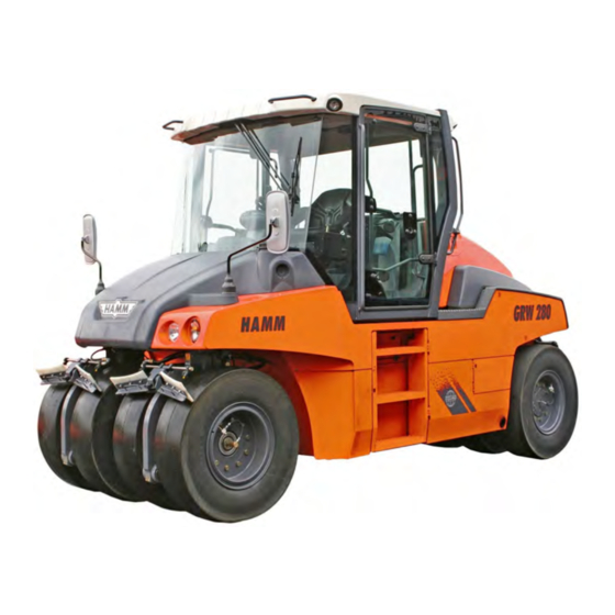
- Page 3 This operating manual is valid for the following roller types: RUBBER WHEELED ROLLER GRW 280-10 GRW 280-12 GRW 280-16 GRW 280-20 GRW 280-24 GRW 280-28 © HAMM AG 2011 2153734_02_BAL_GRW280_H195_en...
-
Page 4: Table Of Contents
Table of contents TABLE OF CONTENTS General........................9 1.00 Introduction......................9 1.00.01 Preface to the operating manual...................9 1.00.02 Product information....................... 9 1.00.03 Guarantee..........................10 1.00.04 Modifications / reservations....................10 1.00.05 Packaging and storage....................... 10 1.00.06 Signs and symbols......................10 1.00.07 Signal words........................11 1.01 Documentation....................13 1.02... - Page 5 Table of contents 2.01 General view of machine................46 2.01.01 Chassis / safety devices......................46 2.01.02 Control stand........................47 2.01.04 Drive unit / diesel engine.....................48 2.01.05 Hydraulic oil supply......................50 2.01.06 Electrical equipment......................52 2.01.08 Drive.............................54 2.01.09 Steering system........................56 2.01.12 Water system........................57 2.01.20 *Tyre heating........................
- Page 6 Table of contents 3.11 Heating / ventilation / cooling..............118 3.12 Stairs to maintenance point.................119 3.13 Opening and closing engine hood..............121 3.14 *Thermal aprons.................... 123 3.15 *Tyre heating....................124 3.15.01 General..........................124 3.15.02 Putting into operation / operation..................126 3.15.03 Taking out of service......................
- Page 7 Table of contents 4.02.03 Checking the filling level of the windshield washer fluid........... 156 4.04 Drive unit - diesel engine................157 4.04.01 General..........................157 4.04.02 Maintenance points at the engine for engine oil change..........158 4.04.03 Changing the filter cartridge for the fuel pre-filter............. 159 4.04.04 *Draining water separator....................160 4.04.05...
- Page 8 Checking *pressure accumulator KAG............188 Tables........................189 5.00 Technical data....................189 5.00.01 Lubrication indications....................... 189 5.00.02 Use of biologic hydraulic oil....................190 5.00.03 Wirtgen Group Lubricants....................191 5.00.04 Coolant conditioning......................194 5.00.05 Fuel............................ 195 5.00.06 Starting torques......................... 196 5.01 Technical data....................197 5.01.01 GRW 280-10........................197...
-
Page 9: General
General Introduction GENERAL When working at the machine please always adhere to the instructions given in your Safety instructions! 000-01 1.00 Introduction 1.00.01 Preface to the operating manual This chapter contains important instructions for the operating personnel on how to operate the machine and to use this operating manual. This operating manual helps you: to become familiar with the machine. -
Page 10: Guarantee
General Introduction 1.00.03 Guarantee No guarantee claims with: operating errors. in the case the spare parts used are no original HAMM spare parts. in the case wrong operating supply items have been used. in the case any additional devices have been refitted an/or installed that have not been approved by HAMM. -
Page 11: Signal Words
General Introduction Directions Information on directions contained in these instructions such as left or right and/or front or rear always refer to the directions of the machine driving forwards. Cross-references Cross-references help you to find quickly sections in this operating manual which supply you with additional important information. - Page 12 General DANGER! Identifies immediate danger. If this risk is not prevented, this causes death or severe personal injuries. 001-01 WARNING! Refers to situations that may be dangerous. If this situation is not avoided, fatality or very serious injuries may be caused. 002-01 CAUTION! Refers to situations that may be dangerous.
-
Page 13: Documentation
General Documentation 1.01 Documentation This operating manual is intended to make the operating personnel familiar with basic work steps / activities of and with the machine. The entire operating manual consists of: Safety instructions Operating manual of the machine Operating manual of the diesel engine If necessary, additional information The entire operating manual must always be available at the machine and be accessible to the authorized operating personnel at all times. -
Page 14: Use
General 1.02 1.02.01 Intended use The machine represents state-of-the-art technology and complies with all valid safety regulations concerning its intended use at the time the machine was launched on the market. When designing the machine it was not possible to avoid forseeable misuse or residual risks without restricting the machine's intended functionality. -
Page 15: Reasonably Forseeable Misuse
General 1.02.02 Reasonably forseeable misuse In the case of reasonably forseeable misuse and/or improper use of the machine, the manufacturer's warranty period will expire and the operator will solely be responsible. Reasonably forseeable misuse is: Non-compliance with this operating manual. Operating errors by operating personnel not qualified or instructed. -
Page 16: Climatic Conditions
General Danger of life / risk of personal injury when operating the machine due to: Misuse. Improper operation. Transport. Missing protective equipment. Defective and/or damaged components. Operation / usage by personnel not trained and/or instructed. The machine may cause risk to the environment with: Improper operation. -
Page 17: Environmental Protection
General Environmental protection WARNING! Explosion! Risk of injury due to burns and moving parts. Do not use aerosol start-up aid (e.g. aether). Do not use any liquids as start-up aid (e.g. alcohol). 002-02 Extensive ambient See operating manual of diesel engine. temperature, extensive height 611-04 1.03... -
Page 18: Ec Confirmity
General EC confirmity 1.05 EC confirmity The declaration of conformity is part of the documentation provided separately by HAMM and will be submitted to you togehter with the machine. The pictogram represents the machine's conformity with relevant EU Directives. The CE mark of the machine is part of the type plate. -
Page 19: Type Plate
General Type plate 1.06 Type plate The entire marking represents an official document and must not be altered or effaced. Please state the VIN and the type of your machine for every spare part order. Type plate of machine The type plate is fixed to the machine frame (see page 46). -
Page 20: Noise And Vibration Requirements
General Noise and vibration requirements Type plate roll-over protection The roll-over protection, ROPS, approved by the manufacturer for this ROPS machine is marked by a type plate attached at the cabin / roll-over bar (see page 47). Type / type series (part of the Cabin / ROPS identification VIN) number... - Page 21 General Noise and vibration requirements Vibration indication on the Whole body vibration operator panel The weighted rms values of the acceleration with whole body vibrations on the operator's seat have been accessed in accordance with EN1032 and do not exceed a = 0.5 m/s².
-
Page 22: Personnel
General Personnel 1.08 Personnel 1.08.01 Qualification and duties Operating personnel All activities at the machine must be carried out by authorised operating personnel only. In this operating manual the term operating personnel refers to all authorised persons that are responsible for operating, maintaining, instaling, setting up, cleaning, repairing or transporting the machine. -
Page 23: General Safety Instructions
General General safety instructions Please adhere to the following instructions: Please make yourself familiar with the machine's and the loading vehicle's dimensions. Wear reflective clothing. For marshalling please use voice radio (e.g when loading with a crane) or via hand signals (e.g. when reversing the machine). 602-07 1.09 General safety instructions... -
Page 24: Danger Zone
General Danger zone 1.10 Danger zone The machine's danger zone is divided into the areas inactive and moving. Zone "inactive" With the machine put out of operation and with the diesel engine switched off, an area 1 metre around the machine is defined as danger zone. -
Page 25: Loading And Transport
General Loading and transport 1.11 Loading and transport Regulations and provisions When loading rollers onto lorries, trailers or semitrailers, it is obligatory to secure the load properly. The duty for tie-down on street vehicles arises from StVO § 22, StVO § 23, StVZO § 30, StVZO § 31, HGB § 412 as well as from VDI guideline 2700 or other local requirements. - Page 26 General Loading and transport Load securing Special notes Variant and variant may be combined. The lashing devices must not necessarily be arranged crosswise. Do not use any lashing device unless it is of sufficient dimension, bears the corresponding marking, and has been subjected to a valid inspection.
- Page 27 General Loading and transport Loading table 1 — applicable to machine weight ≤ 10000 kg Maximum permissible ramp slope: 17,5 % (~10°) with substructure ballast (UB) 28,5 % (~ 16°) without substructure ballast (UB) Chain lashing device: Nominal chain size / quality class and LC in daN Strap lashing device: LC in daN Load platform lashing point strength: in daN α...
- Page 28 General Loading and transport Loading table 2 — applicable to machine weight ≤ 12600 kg Maximum permissible ramp slope: 17,5 % (~10°) with substructure ballast (UB) 28,5 % (~ 16°) without substructure ballast (UB) Chain lashing device: Nominal chain size / quality class and LC in daN Strap lashing device: LC in daN Load platform lashing point strength: in daN α...
- Page 29 General Loading and transport Loading table 3 — applicable to machine weight ≤ 15500 kg Maximum permissible ramp slope: 17,5 % (~10°) with substructure ballast (UB) 28,5 % (~ 16°) without substructure ballast (UB) Chain lashing device: Nominal chain size / quality class and LC in daN Strap lashing device: LC in daN Load platform lashing point strength: in daN α...
- Page 30 General Loading and transport Loading table 4 — applicable to machine weight ≤ 16000 kg Maximum permissible ramp slope: 17,5 % (~10°) with substructure ballast (UB) 28,5 % (~ 16°) without substructure ballast (UB) Chain lashing device: Nominal chain size / quality class and LC in daN Strap lashing device: LC in daN Load platform lashing point strength: in daN α...
- Page 31 General Loading and transport Loading table 5 — applicable to machine weight ≤ 20600 kg Maximum permissible ramp slope: 17,5 % (~10°) with substructure ballast (UB) 28,5 % (~ 16°) without substructure ballast (UB) Chain lashing device: Nominal chain size / quality class and LC in daN Strap lashing device: LC in daN Load platform lashing point strength: in daN α...
- Page 32 General Loading and transport Loading table 6 — applicable to machine weight ≤ 24000 kg Maximum permissible ramp slope: 17,5 % (~10°) with substructure ballast (UB) 28,5 % (~ 16°) without substructure ballast (UB) Chain lashing device: Nominal chain size / quality class and LC in daN Strap lashing device: LC in daN Load platform lashing point strength: in daN α...
- Page 33 General Loading and transport Loading table 7 — applicable to machine weight ≤ 28500 kg Maximum permissible ramp slope: 17,5 % (~10°) with substructure ballast (UB) 28,5 % (~ 16°) without substructure ballast (UB) Chain lashing device: Nominal chain size / quality class and LC in daN Strap lashing device: LC in daN Load platform lashing point strength: in daN α...
-
Page 34: Stickers On The Machine
General Stickers on the machine Explanation on how to use WARNING! loading tables: High accelerating forces will occur during transport! Danger to life if the machine rolls away or tilts sideways inadvertently. Determine α and β angles at every of the 4 lashing points. Determine the lashing point strength at the vehicle, depending on angles α... -
Page 35: Warning Labels
General Stickers on the machine 1.12.01 Warning labels Read documentation Read operating manual and safety instrucions before you start working with the machine or maintaining it. Ignoring this instructions can cause serious injuries or fatality. Seat belt obligatory (only with ROPS cabin or ROPS roll-over bar) Risk of being thrown out of tipping machine can cause serious injuries or fatality. - Page 36 General Stickers on the machine Motor Stop Hazard due to rotating parts! With the machine running, serious injuries or fatality may be caused. Prior to maintenance work, shut down engine and remove ignition key. Wait until all machine components have come to a standstill.
- Page 37 General Stickers on the machine Edge pressing assembly Risk of crushing! Pinch point can cause serious injuries or fatality. Keep away. Prior to maintenance and adjustment works, shut down machine and remove ignition key. Fan blade Hazard due to rotating parts! With the machine running, serious injuries or fatality may be caused.
- Page 38 General Stickers on the machine Folding joint Risk of crushing! Pinch point can cause serious injuries. Keep away. Running over hazard Machine movements can cause serious injuries or fatality. Keep away. Danger of overturning Pay attention that there is sufficient stability when working with rollers of small roller drum width.
- Page 39 General Stickers on the machine Battery isolating switch Dangerous situation. Actuate the battery isolating switch only with the enginge stopped. Before you start with service works, read the operating and maintenance instructions. 12 V fuses Diesel Diesel tank! Use diesel with a sulphur content of less than 0.5 %. Pay attention to standards.
-
Page 40: Information Sign
General Stickers on the machine Read documentation Read operating manual before you start working with the machine or maintaining it. First-aid kit Panolin Biodegradable hydraulic oil in use. 1.12.02 Information sign In the following you will find a list of all information signs. Illustrations and values of the signs may vary depending on the machine type. - Page 41 General Stickers on the machine Sprinkling Water tank filling Water tank outlet Additive sprinkling Water tank inlet of additive sprinkling Water tank outlet of additive sprinkling Water pump © HAMM AG 2011 2153734_02_BAL_GRW280_H195_en...
- Page 42 General Stickers on the machine Hydraulic oil filling level Hydraulic oil reservoir inlet Hydraulic oil reservoir outlet Socket 12V Engine oil outlet Water sump fuel filter outlet Coolant filling level 2153734_02_BAL_GRW280_H195_en © HAMM AG 2011...
- Page 43 General Stickers on the machine Coolant inlet Inflation pressure Tyre without water filling Inflation pressure Tyre with water filling Guaranteed sound power level Expert inspection test badge © HAMM AG 2011 2153734_02_BAL_GRW280_H195_en...
- Page 44 General Stickers on the machine Maintenance overview 2153734_02_BAL_GRW280_H195_en © HAMM AG 2011...
-
Page 45: Description
Description Technical characteristics of the machine DESCRIPTION When working at the machine please always adhere to the instructions given in your Safety instructions! 000-01 2.00 Technical characteristics of the machine Drive Hydrostatic drive of rear axle Infinitely variable Single lever operation Steering Hydrostatic servo-assisted steering Large steering angle to both sides Level compensation upwards and downwards... -
Page 46: General View Of Machine
Description General view of machine 2.01 General view of machine This operating manual applies to several types of this series. Therefore it is possible that these instructions include descriptions of operating elements not installed on your machine. 000-03 2.01.01 Chassis / safety devices Stickers indicating dangers Towing loop for crane loading Towing loop... -
Page 47: Control Stand
Description General view of machine 2.01.02 Control stand ROPS cabin Handles Operator's seat console, fixed, *Operator's seat console, infinitely variable Operator's cabin Steering column Stacker for operating manual / Heating / ventilation / cooling first aid kit ROPS cabin type plate cabin door Position for *fire extinguisher Windshield washer liquid... -
Page 48: Drive Unit / Diesel Engine
Description General view of machine 2.01.04 Drive unit / diesel engine Diesel engine with drive units Coolant inlet Fuel tank Fuel system Fuel intake Air filter Turbo-supercharger / exhaust Oil inlet system Cooling system Coolant compensator tank Fuel prefilter Oil dip stick Fuel filter Fuel intake Air filter... - Page 49 Description General view of machine Oil outlet © HAMM AG 2011 2153734_02_BAL_GRW280_H195_en...
-
Page 50: Hydraulic Oil Supply
Description General view of machine 2.01.05 Hydraulic oil supply Hydraulic oil reservoir Oil inlet and oil dipstick with ventilation filter Hydraulic oil filter 2153734_02_BAL_GRW280_H195_en © HAMM AG 2011... - Page 51 Description General view of machine Oil outlet © HAMM AG 2011 2153734_02_BAL_GRW280_H195_en...
-
Page 52: Electrical Equipment
Description General view of machine 2.01.06 Electrical equipment Chassis Battery isolating switch Fuses Battery Battery isolating switch Fuses Fuse occupancy 2153734_02_BAL_GRW280_H195_en © HAMM AG 2011... - Page 53 Description General view of machine Main fuses Battery Main fuses Battery Battery compartment screw connectionBattery compartment screw connection Battery compartment screw connection Engine compartment Plug engine control unit © HAMM AG 2011 2153734_02_BAL_GRW280_H195_en...
-
Page 54: Drive
Description General view of machine 2.01.08 Drive Drive Brake drive Gear drive Smooth tyre, oil outlet, filling level control screw, oil inlet Rear wheel Oil outlet Filling level control screw Oil inlet Smooth tyre 2153734_02_BAL_GRW280_H195_en © HAMM AG 2011... - Page 55 Description General view of machine Smooth tyre Scraper Smooth tyre [*C] Tire filling system Front wheel [*A] Valve [*B] Tyre inflator hose © HAMM AG 2011 2153734_02_BAL_GRW280_H195_en...
-
Page 56: Steering System
Description General view of machine 2.01.09 Steering system Steering cylinder Bearing block / oscillation arm Tie rod Steering cylinder Tie rod 2153734_02_BAL_GRW280_H195_en © HAMM AG 2011... -
Page 57: Water System
Description General view of machine 2.01.12 Water system Sprinkler nozzles Water inlet Water tank Water outlet Water filter Water pump Sprinkler nozzles Water outlet Water filter Water pump © HAMM AG 2011 2153734_02_BAL_GRW280_H195_en... - Page 58 Description General view of machine Additive sprinkling Additive sprinkling water pump [B] Additive filter Inlet additive tank 2153734_02_BAL_GRW280_H195_en © HAMM AG 2011...
-
Page 59: Tyre Heating
Description General view of machine 2.01.20 *Tyre heating Tyre heating Ignition unit Infrared radiator group Gas supply pipe Liquid gas bottles Main stop valve 11-step controller Skid catch Skid Bottle bank Gas bottle shut-off valve © HAMM AG 2011 2153734_02_BAL_GRW280_H195_en... -
Page 60: Edge Pressing And Cutting Assembly (Kag)
Description General view of machine 2.01.27 *Edge pressing and cutting assembly (KAG) Pressing disk Pipe with sprinkler nozzle Lubrication nipple Hydraulic cylinder Additional holder (e.g. with cutting disc) 2153734_02_BAL_GRW280_H195_en © HAMM AG 2011... -
Page 61: Special Equipment
Description General view of machine 2.01.40 Special equipment Accessory [*A] Working spotlight Loudspeaker Rear-view mirror [*D] Radio / CD [*E] Tachograph Safety belt [*G] Second drive lever [*A] Spare wheel and fixing device © HAMM AG 2011 2153734_02_BAL_GRW280_H195_en... - Page 62 Description General view of machine Tool box Comfort loading Lashing point 2153734_02_BAL_GRW280_H195_en © HAMM AG 2011...
- Page 63 Description General view of machine Thermal aprons Thermal front aprons Thermal rear aprons © HAMM AG 2011 2153734_02_BAL_GRW280_H195_en...
-
Page 64: General View Of Instruments And Operating Elements
Description General view of instruments and operating elements 2.02 General view of instruments and operating elements All instruments and operating elements are marked by numbers. You will find a description in chapter 3 under the corresponding element. 000-04 2.02.02 Control stand Steering column [302] Switch EMERGENCY STOP [501] Drive lever... - Page 65 Description General view of instruments and operating elements Switch console front [216] Pilot light, cold start assistance[245A] Pilot light, front tyre heating [245B] Pilot light, rear tyre heating [303] Flashing indicator switch [305] Warning flasher switch [307] Switch lighting [310] Switch, electrical system / [*311] Rotating light switch engine start [*322] Tyre heating...
- Page 66 Description General view of instruments and operating elements Operator's cabin, rear wall [405] Socket 12 V ROPS, area behind the seat [405] Socket 12 V 2153734_02_BAL_GRW280_H195_en © HAMM AG 2011...
- Page 67 Description General view of instruments and operating elements Operator's cabin door [537] Locking system cabin door Handle Actuation button Driver's seat [520] Seat adjustment weight / [*521] Seat adjustment forward - height backward [522] Seat backrest adjustment [523] Seat adjustment elbow-rest Driver's seat, rigid The rigid driver's seat is positioned at the right-hand side in the cabin / ROPS, making access to the cabin / ROPS difficult from...
- Page 68 Description General view of instruments and operating elements Control unit normal mode [101] Display system info [237] Pilot light fuel [301] Switch signal horn [353] Switch parking brake monitoring [375] Switch system info Control unit travelling [108] Display driving speed [314] Gear shifting 2153734_02_BAL_GRW280_H195_en ©...
- Page 69 Description General view of instruments and operating elements Control unit sprinkling [207] Pilot light sprinkling [232] Pilot light sprinkling stage [238] Pilot light filling level sprinkling [317] Switch sprinkling [373] Switch sprinkling stage Operating unit tyre filling system [*115] Display air pressure tyre [*360A] Switch tyre filling system [*360B] Switch tyre filling system - fast ©...
- Page 70 Description General view of instruments and operating elements Asphalt temperature control unit [*113] Display asphalt temperature [*379] Switch asphalt temperature Control unit warning lamp [201] Pilot light charge current [202] Pilot light oil pressure [203] Pilot light air filter [204] Pilot light parking brake [206] Pilot light coolant level [214] Pilot light hydraulic oil filter [220] Pilot light STOP...
-
Page 71: Drive Unit / Diesel Engine
Description General view of instruments and operating elements 2.02.04 Drive unit / diesel engine [356] Battery isolating switch [538] Steps [530] Manual pump parking brake [538] Steps © HAMM AG 2011 2153734_02_BAL_GRW280_H195_en... -
Page 72: Drive
Description General view of instruments and operating elements 2.02.08 Drive Tyre scraper (brushes) [536] Locking device scraper Tyre scraper (PUR) [536] Locking device scraper 2153734_02_BAL_GRW280_H195_en © HAMM AG 2011... -
Page 73: Operation
Operation Instruments and operating elements OPERATION 3.00 Instruments and operating elements The instruments and operating elements are arranged in this section in ascending order according to their number. These numbers in squared brackets are used as a reference in the description of the elements. - Page 74 Operation Instruments and operating elements 108 Driving speed Indication of the driving speed in km/h or mph. 108-10 113 Asphalt temperature If the machine is equipped without measuring system no indicator appears. Asphalt temperature display under the machine in °C or °F. Limit for asphalt temperature Using the switches [379] it is possible to adjust the limit values of the asphalt temperature.
-
Page 75: Pilot Lights
Operation Instruments and operating elements 3.00.02 Pilot lights The colours of the pilot lights mark the value of the incident. Meaning of the colours: Danger, important reminder Yellow Warning, notice, malfunction Green Switch-in check 000-06 201 Charge current Flashing during operation indicates missing charging current. 201-06 202 Engine oil pressure Flashing during operation indicates insufficient oil pressure. - Page 76 Operation Instruments and operating elements 204 Parking brake The pilot light flashes when the parking brake is applied and after the actuation of the parking brake control unit [353] and/or the EMERGENCY STOP switch [302]. 204-07 206 Coolant level Flashing during operation indicates that the coolant level in the cooling system of the diesel engine is not sufficient.
- Page 77 Operation Instruments and operating elements 216 Cold start assistance When the electric system is switched on (switch [310] in position I), this indicator lights up. After reaching start temperature, the indicator switches off; then start the diesel engine. 216-04 220 STOP Flashing during operation indicates a serious malfunction of the machine.
- Page 78 Operation Instruments and operating elements 229 Oil temperature of hydraulic system Lighting up during operation indicates improper hydraulic oil temperature. Warm-up phase — lights up YELLOW Elevated — lights up RED Overheating — flashes RED 229-02 232 Sprinkling stage The sprinkling stage is displayed by the pilot lights. A luminous point shows the pre-selected sprinkling stage.
- Page 79 Operation Instruments and operating elements 238 Sprinkling filling level The water tank filling level is displayed by an illuminated pilot light. According to the level, a light point moves between 2/3, 1/3 and 1/10, correspondingly. If the level drops below 1/10 the light point flashes for ca.
- Page 80 Operation Instruments and operating elements 245 Tyre heating The two pilot lights indicate the operating status of the tyre heaters (front and rear infrared radiator groups). Flickering — tyre heating in the ignition phase Steady light — tyre heating ignited, flame is on Front tyre heating Rear tyre heating 245-00...
-
Page 81: Switch
Operation Instruments and operating elements 3.00.03 Switch 301 Signal horn The signal horn sounds as long as this switch is pressed. 301-03 302 EMERGENCY STOP WARNING! Full braking! Danger of injuries due to strong braking force. Activate EMERGENCY STOP only in the event of danger. Do not use the EMERGENCY STOP as operation brake. - Page 82 Operation Instruments and operating elements 303 Flashing lights Direction indicator Curve right — position I (push button flashes) Off — position 0 Curve left — position II (push button flashes) 303-09 305 Warning flashers On — position I (push button flashes) Off —...
- Page 83 Operation Instruments and operating elements 310 Electrical system / engine start The switch (ignition key) supplies the electrical components with power, and starts and stops the diesel engine. 0-position Electrical system — OFF Diesel engine — STOP (key released) Position I Electrical system —...
- Page 84 Operation Instruments and operating elements 317 Sprinkling The switch turns the sprinkling on or off. Water consumption is optimized via a multi-stage automatic interval system. The sprinkling stage can be selected with the switches [373]. On — PRESS Off — PRESS again Continuous pressing of the switch will cause permanent sprinkling.
- Page 85 Operation Instruments and operating elements 332 Front windshield wiper On — position I Off — position 0 332-04 333 Rear windshield wiper On — position I Off — position 0 333-03 338 Windshield washer By pressing the switch up or down, the delivery pump of the windshield washer is switched on.
- Page 86 Operation Instruments and operating elements 353 Parking brake inspection WARNING! Full braking! Danger of injuries due to strong braking force. Only inspect the parking brake when the engine is at a standstill. Do not use the parking brake as the service brake. 002-04 The parking brake is applied only as long as the switch is pressed (pilot light [204] flashes).
- Page 87 Operation Instruments and operating elements 360B Tyre filling system - fast Press this button to toggle "fast tyre inflation" on or off. Actuation is not possible unless the machine is stopped. Engine speed is increased to approx. 2000 rpm. The compressor provides a higher delivery volume.
- Page 88 Operation Instruments and operating elements 379 Asphalt temperature Using the switches you can adjust and save the limit values of the asphalt temperature. Function ▲ ▼ Increase limit value by 1 °C or 1 °F — PRESS ▲ Reduce limit value by 1 °C or 1 °F — PRESS▼ Pressing the button longer you can increase / reduce the value gradually in steps of 5 °C or 5 °F.
-
Page 89: Sockets, Lights
Operation Instruments and operating elements 3.00.04 Sockets, lights 405 Socket 12 V The maximum load on the socket is 100 W (8 A). 405-01 406 Socket 12 V / cigarette lighter Cigarette lighter Press the cigarette lighter until it engages (spiral-wound filament is heated). -
Page 90: Operation Levers, Adjustment Handles
Operation Instruments and operating elements 3.00.05 Operation levers, adjustment handles 501 Drive lever The machine can be equipped with a second drive lever (option). Both drive levers are coupled to each other. The following description applies for both drive levers. The drive lever determines the driving direction and speed. - Page 91 Operation Instruments and operating elements 503 Multifunction handle NOTICE Risk of damage to the edge pressing and cutting assembly (KAG)! Damage due to unfavourable force transmission. Apply KAG only when travelling forward! 004-06 The edge pressing and cutting equipment (KAG) is lifted and lowered as long as one side of the switch [B] is pressed.
- Page 92 Operation Instruments and operating elements 520 Seat adjustment weight / height WARNING! Uncontrolled movements! Risk of injury by uncontrolled movements when changing the seat pedestral position. Operate the machine only in an admissable seat position. Only drive the machine with latched seat pedestal. Do not adjust the seat pedestal during driving.
- Page 93 Operation Instruments and operating elements 522 Seat backrest adjustment WARNING! Uncontrolled movements! Risk of injury by uncontrolled movements when changing the seat pedestral position. Operate the machine only in an admissable seat position. Only drive the machine with latched seat pedestal. Do not adjust the seat pedestal during driving.
- Page 94 Operation Instruments and operating elements 524 Seat adjustment rotation WARNING! Uncontrolled movements! Risk of injury by uncontrolled movements when changing the seat pedestral position. Operate the machine only in an admissable seat position. Only drive the machine with latched seat pedestal. Do not adjust the seat pedestal during driving.
- Page 95 Operation Instruments and operating elements 525 Seat adjustment left - right WARNING! Uncontrolled movements! Risk of injury by uncontrolled movements when changing the seat pedestral position. Operate the machine only in an admissable seat position. Only drive the machine with latched seat pedestal. Do not adjust the seat pedestal during driving.
- Page 96 Operation Instruments and operating elements 530 Manual pump parking brake To tow the machine with a defective diesel engine and/or a defective hydraulic system it is necessary to loosen the spring-operated brakes using the manual pump (see page 114 sqq.). Lever Screw Lock nut...
- Page 97 Operation Instruments and operating elements 537 Locking system cabin door If opened the cabin door can be interlocked with the cabin. Open cabin door: 1. Press handle [A], open cabin door and interlock with cabin. Unlock cabin door: 1. Pull actuation button [B], the locking system is open. 537-00 538 Steps The steps to the control stand can also be used as steps to the...
-
Page 98: Prior To Machine Start
Operation Prior to machine start 3.01 Prior to machine start General DANGER! Uncontrolled driving behaviour! Risk of fatal injury due to the machine's own driving movements. It is essential to perform a setup after working on the electronic components associated with the control. It is not admitted to operate the machine without setup. - Page 99 Operation Prior to machine start Fuel 1. Never drive the machine until the fuel tank is empty. Check the filling level of the fuel tank in time. Fill up the fuel tank already in the evening. This avoids the formation of condensed water in the fuel tank.
- Page 100 Operation Prior to machine start WARNING! Collision with items and vehicles driving past! Risk of injury due to shocks or crushing. When on outer seat position, no parts of the steering console or seat pedestal may protrude on the side of the cabin / ROPS. 002-24 Inadmissable seat position It is not admissable to operate the machine if parts protrude the steering...
-
Page 101: Engine Start
Operation Engine start 3.02 Engine start General The starting process may last 20 seconds as a maximum; otherwise, the starting motor will be overheated and destroyed. There must be pauses between the individual starting processes in order to allow the staring motor to cool down. - Page 102 Operation Engine start Before driveaway WARNING! Long stopping distance! Risk of fatal injury due to braking delay with viscous hydraulic oil. In case of low external temperatures, in particular when below freezing, wait a few minutes after starting the engine until driveaway. Warm up the machine during the warming phase with moderate speed and low load until the oil in the hydraulic system has heated to approx.
-
Page 103: Driving
Operation Driving 3.03 Driving Driveaway 1. Wait until the STOP pilot light [220] and the pilot light [239] do not light up anymore. 2. If the pilot light STOP [220] and the pilot light [239] have not gone out after ca. 30 seconds after the diesel engine was started, it is not allowed to run the machine. - Page 104 Operation Driving Velocity range WARNING! Full braking! Danger of injuries due to strong braking force. In case of visible obstacles reduce speed in good time. Longer uphill or downhill slopes must always be driven in velocity range 1. 002-61 Using switch [314] you can switch from the velocity range 1 to velocity range 2 and vice versa.
-
Page 105: Stopping, Switching Off Engine, Leaving Machine
Operation Stopping, switching off engine, leaving machine 3.04 Stopping, switching off engine, leaving machine WARNING! Uncontrolled driving behaviour! Risk of fatal injury due to the machine's own driving movements. Switch off diesel engine even if you leave the operator platform only for short time. - Page 106 Operation Stopping, switching off engine, leaving machine Switch off engine Do not switch off engine directly after full load operation. Instead, let it run for 1-2 minutes with idle speed for temperature compensation purposes. 1. Key [310] — I → 0 The battery discharges rapidly if the engine is at a standstill and the electrical system is switched on (switch [310] in position I).
-
Page 107: Operation Monitoring
Operation Operation monitoring 3.05 Operation monitoring Keep an eye on the control and indication instruments on the instrument board during operation. Pilot lights inform the driver about the operating stages of the individual machine components and indicate faults. The urgancy of taking action is subdivided into three stages. Danger, important reminder The pilot light STOP [220] is active. -
Page 108: Sprinkling
Operation Sprinkling 3.06 Sprinkling General The pressure sprinkling ensures a reliable moistening of the roller drums / tyres during blacktop works and thus prevents bituminous materials from adhering to the drums. An electric water pump supplies the sprinkling system with water so that the water consumption can be optimally adjusted to the deployment conditions using the installed automatic sprinkling. - Page 109 Operation Sprinkling On risk of frost Frozen water leads to damage to the sprinkler system. Therefore, it must be drained before frost begins. Emptying the water sprinkling system: 1. Remove a sealing cap [B] per sprinkler pipe [A] (observe internal gasket ring).
-
Page 110: Additive Sprinkling
Operation *Additive sprinkling 3.07 *Additive sprinkling General The additive sprinkling enables a moistening of the wheels with a separating compound. This prevents that bitumen sticks on tyres when laying blacktops. This is the only way to make a neat and even covering. The emulsion may only be mixed of parting agent concentrate and water according to the indications of the parting agend producer (Observe regulations for environment protection). -
Page 111: Scrapper Tyres
Operation Scrapper tyres 3.08 Scrapper tyres General The scrapers [A] are designed to remove clogging dirt from the surface of the roller drums / tyres when working on soft, adhesive ground. With grounds that are not clingy or with transporting operations the scrapers can be lifted away from the roller drums / tyres. -
Page 112: Starting With Jump Leads
Operation Starting with jump leads 3.09 Starting with jump leads Observe precaution measures for handling batteries (see Safety Preparation instructions). Pay attention to the nominal voltage of the batteries. A discharged battery can freeze already at 0 °C (32 °F). It is essential that you defrost a frozen battery in a warm room before connecting it with jump leads. - Page 113 Operation Starting with jump leads Removing leads 1. To prevent overloads in the electrical system, switch on an electrical component in the discharged vehicle (e.g. driving light) before removing the jump leads. 2. Remove the jump leads in reverse order. 743-00 ©...
-
Page 114: Towing
Operation Towing 3.10 Towing General WARNING! Brake out of order! Risk of fatal injury due to unintentional rolling away of the machine. Prior to releasing the brake, secure the machine against rolling away with wedges. 002-23 2153734_02_BAL_GRW280_H195_en © HAMM AG 2011... - Page 115 Operation Towing Towing of the machine assumes sufficient knowledge of the functioning of the hydrostatic drive and the operation of the multi-disc spring operated brake. The preparations for towing may only be carried out by experienced personnel who are aware of the dangers. The machine may only be fastened at the towing loops [A] and only be towed with a towing bar.
- Page 116 Operation Towing After towing 1. Shut down the diesel engine. 2. Secure machine against rolling away with wedges or blocks. 3. Reestablish frictional connection of the hydrostatic drive (see text below) 4. Actuate parking brakes (see text below). 5. Remove towing bar. 717-07 Separating the hydrostatic drive power train...
- Page 117 Operation Towing Making the parking brakes inoperational Only for the purpose of towing in case of a defective diesel engine or defective hydraulic system the pretension of the spring-loaded brakes may be reduced using the manual pump [530]. 1. Fold away right stairs. 2.
-
Page 118: Heating / Ventilation / Cooling
Operation Heating / ventilation / cooling 3.11 Heating / ventilation / cooling General The comfort, well-being and good condition of the driver are largely dependent on a properly set heating and ventilation. This especially applies for the cold seasons. By adjusting the leg-room heating and opening the ventilation nozzles required, a temperature distribution is achieved with the pleasant effect of having warm feet but a cool head. -
Page 119: Stairs To Maintenance Point
Operation Stairs to maintenance point 3.12 Stairs to maintenance point General The steps to the control stand can also be used as steps to the maintenance points. For that, you can swing out the steps and lock them to the chassis. It is on the right of the machine in direction of travel. Prior to unfolding the stairs: 1. - Page 120 Operation Stairs to maintenance point Folding in step 1. Pull handle [A] upwards and pull bar [B] out of lockable opening [C]. 2. Turn handle [A] into vertical position. 3. Retract stairs into operating position and click into place (and secure).
-
Page 121: Opening And Closing Engine Hood
Operation Opening and closing engine hood 3.13 Opening and closing engine hood General WARNING! Uncovered, rotating parts! Risk of injury due to rotating parts. Only open the engine hood or engine room doors when the engine is at a standstill. 002-09 WARNING! Hot surface, hot fluids! - Page 122 Operation Opening and closing engine hood Closing the engine hood WARNING! Danger of toppling! Risk of crushing! If you do not adhere to safety measures when closing the engine hood you may fall down or crush body parts! Prior to closing the engine hood make sure that there are no persons within the hazardous area of the stand space [A] marked.
-
Page 123: Thermal Aprons
Operation *Thermal aprons 3.14 *Thermal aprons General Thermal aprons and tyre heating ensure an optimum tyre temperature even at a low ambient temperature or when exposed to wind. This avoids asphalt sticking to the tyres. Thermal aprons do not provide active heating. They are used to form a space around the rubber tyres which is closed at its lateral and upper sides, and allows to accumulate the heat rising up from the hot asphalt. -
Page 124: Tyre Heating
Operation *Tyre heating 3.15 *Tyre heating 3.15.01 General Funtional diagram Infrared radiator with ignition Pressure reducer 50 mbar wire Shut-off valve Pressure reducer, flow controller Stop cock Gas bottle General To prevent bituminous materials from adhering to tyres the tyres' contact surfaces are preheated by thermal radiation (infrared radiation). - Page 125 Operation *Tyre heating Gas supply and heat output Heating is done using propane / butane liquid gas in commercially available 11 kg gas bottles. The heat requirement is approx. 55 000 kcal/h. Liquid gas has a heat output of approx.12.7 kW (approx. 11 000 kcal/h); i.e., consumption will reach a maximum of 6-8 kg of gas per hour.
-
Page 126: Putting Into Operation / Operation
Operation *Tyre heating 3.15.02 Putting into operation / operation WARNING! Gas explosion! Danger to life due to escaping and exploding gas! Inspect the entire system for leaks on a regular basis (e.g., using spray). Do not smoke, and do not use any open fire or other source of ignition. - Page 127 Operation *Tyre heating Be sure to perform every work step exactly in the sequence indicated. 1. Put the machine in its "start position before starting" as indicated in chapter Engine start! 2. Remove the cover from the bottle bank (if available). 3.
- Page 128 Operation *Tyre heating The gas supply is open, but the system has not been fired completely yet. When a flame goes off at one or two infrared radiator groups [B], this is also indicated by one or two flickering pilot lights. Steady light —...
-
Page 129: Taking Out Of Service
Operation *Tyre heating 3.15.03 Taking out of service 1. Set the machine to the status described in chapter Stopping, switching off engine, leaving machine. 2. Remove the cover from the bottle bank (if available). 3. Unlock the transport slide [C], and pull it out to the front. 4. - Page 130 Operation *Tyre heating WARNING! Cold burn! Icing may occur at the surface of a liquid gas bottle and/or at the valves when a big amount of liquid gas is withdrawn. Adjust gas withdrawal correctly. Wear personal protective equipment. Ice which may have formed must not be removed unless by a slow process.
-
Page 131: Tyre Filling System
Operation *Tyre filling system Transport information The German regulation on the carriage of dangerous goods by road and rail (GGVSE) and the provisions of ADR (European Agreement concerning the International Carriage of Dangerous Goods by Road) include exemption rules allowing the transport of these gas bottles by the rollers equipped with tyre heaters. -
Page 132: Asphalt Thermometer
Operation Fast tyre inflation Use switch [360B] to toggle "fast tyre inflation" either on or off. This function is not available unless the driver is seated on the driver's seat, and the drive lever is locked in the 0 position lock. (pilot light [204] flashes)! 000-22 On —... - Page 133 Operation *Asphalt thermometer Asphalt temperature control unit [*113] Display asphalt temperature [*379] Switch asphalt temperature Adjusting limit The actual or pre-set asphalt temperature is displayed on the indicator [113]. Select the maximum and minimum asphalt temperature limits with the switches [379]. 1.
-
Page 134: Spare Wheel Retainer
Operation *Spare wheel retainer 3.18 *Spare wheel retainer WARNING! Heavy weight! Risk of crushing under the heavy weight of the wheel. Ensure that there is a sufficient distance to your hands and feet when lowering the wheel to ground level. Call a second person to perform this operation together if possible. -
Page 135: Driving On Public Roads (Stvzo)
Operation *Driving on public roads (StVZO) To mount the wheel to the spare wheel holder, proceed accordingly. 768-00 3.19 *Driving on public roads (StVZO) The government of Upper Palatinate grants an exception permit (see the details indicated on the original) for the road rollers of the GRW 280 type pursuant to section 70, subsections 1 and 2 of the German Road Traffic Type Approval Law (StVZO). -
Page 136: Adding / Reducing Ballast
Operation Adding / reducing ballast 3.20 Adding / reducing ballast DANGER! Danger to life! Danger of overturning: Centre of gravity may shift when adding / reducing ballast and cause serious injuries or fatality. Add / reduce ballast only on ballast spaces which are axially symmetrical. -
Page 137: Reducing And Adding Ballast
Operation Adding / reducing ballast 3.20.01 Reducing and adding ballast Jacking point for lifting jack / chassis stand Reducing ballast WARNING! Heavy weight! Ballast falling down - risk of crushing. Secure ballast sufficiently against falling down (e.g. apply a lifting jack). - Page 138 Operation Adding / reducing ballast For detailed information on how to fasten the ballast compartment covers, please refer to the spare parts catalogue. 3. Release the fastening screws [A], remove the ballast space cover and store securely. 4. Secure ballast sufficiently against falling down (e.g. apply a lifting jack).
- Page 139 Operation Adding / reducing ballast Adding ballast NOTICE Ballast distribution! Insert the ballast into the appropriate ballast spaces! The ballast for the R2 and L2 ballast spaces can be inserted on the right side in the direction of travel as well as on the left side in the direction of travel.
-
Page 140: Maintenance
Maintenance General maintenance instructions MAINTENANCE When working at the machine please always adhere to the instructions given in your Safety instructions! 000-01 4.00 General maintenance instructions This machine requires care and maintenance like any other technical device. The extent and the frequency of the maintenance work depends essentially of the operating and deployment conditions, which are very different in many cases. -
Page 141: Maintenance Overview
Maintenance General maintenance instructions Brake oil The filling level of the brake oil in the storage tank is electrically supervised. If the pilot light [239] flashes: 1. Park the machine out of the danger zone. 2. Switch off diesel engine and remove ignition key. 3. - Page 142 Maintenance General maintenance instructions Every 250 operating hours Checking the scrapers see page 172 sqq. Checking filling level of (driving) gear oil see page 172 sqq. Checking filling level brake oil see page 172 sqq. Lubricating the steering cylinder bolt see page 182 sqq.
- Page 143 Maintenance General maintenance instructions Every 2000 operating hours Checking the EMERGENCY STOP see page 150 sqq. function when machine is driving Cleaning the water sprinkling unit see page 185 sqq. Replacing the hydraulic oil see page 169 sqq. Changing the brake oil see page 172 sqq.
-
Page 144: Running-In Regulations
Maintenance General maintenance instructions 4.00.03 Running-in regulations After 50 operating hours Maintenance of the tyre mounting 1. Checking the wheel nuts / wheel bolts for tightness. Maintenance driving gear 1. Exchange (driving) gear oil. Maintenance pressure reservoir, pressure accumulator and pressure accumulator KAG 1. -
Page 145: Required Maintenance Parts
2160577 tenance intervals All necessary maintenance parts for the corresponding maintenance interval are assembled in a service kit. You find the current order numbers for individual service kits in the WIRTGEN GROUP document Parts and more. © HAMM AG 2011... -
Page 146: Important Information About Maintenance Works
Maintenance General maintenance instructions 4.00.05 Important information about maintenance works General Specialist knowledge is necessary for the execution of some inspection and maintenance works; these cannot be given in the scope of these operating instructions. We recommend to have these works performed by trained specialised staff. - Page 147 Maintenance General maintenance instructions WARNING! Explosion, acid! Risk of injury due to moving parts and caustic acids. Do not put any tools on the battery. 002-11 WARNING! Fluids under pressure! Risk of injury due to fluids spurting out under pressure. Carry out maintenance works only with depressurized hydraulic systems.
-
Page 148: Welding Works On The Machine
Maintenance General maintenance instructions 4.00.06 Welding works on the machine Observe the operating manual of the diesel engine. Preparation In order to protect electronic components as e. g. central processing unit, monitor unit, sensors, relays etc., all connectors must be pulled out prior to welding work. - Page 149 Maintenance General maintenance instructions Open service flap [D] using the ignition key. Disconnect plugs XD2, X11 and X12. 5. Connect negative terminal of the welding appliance in the vicinity of the weld. 6. Pay attention to the components in the vicinity of the weld. 7.
-
Page 150: Chassis / Safety Features
Maintenance Chassis / safety features 4.01 Chassis / safety features 4.01.01 General Check operating and safety instructions on the machine. Replace Adhere to the following damaged and/or non-readable signs. instructions: Ensure that hinges and links move easily and lubricate lightly. Check the warning devices (signal horn, reflectors, back-up alarm, blinkers and warning flashers). -
Page 151: Checking The Emergency Stop Function
Maintenance Chassis / safety features Function test 1. Start the diesel engine [310]. 2. Select velocity range 1 [314]. 3. Keep the switch [353] pushed. 4. Push the drive lever [501] shortly in forward direction. 5. Bring the drive lever [501] into central position again before releasing the switch [353]. -
Page 152: Lubricating Hinges Of Stairs
Maintenance Chassis / safety features 1. Select velocity range 1 [314]. Function test when machine is driving (annually) 2. Press EMERGENCY STOP [302] with low speed 0.5 km/h (0.3 mph). The machine: Stops immediately. Switches off the working functions. Shuts down the diesel engine. 813-17 4.01.04 Lubricating hinges of stairs... -
Page 153: Lubricating Hinges Of The Engine Hood
Maintenance Chassis / safety features 4.01.05 Lubricating hinges of the engine hood 1. Switch off diesel engine and remove ignition key. 2. Lubricate lubrication points [A] (2 items). Lubricant only admissible if containing this marking (see page sqq.). 828-00 4.01.06 Lubricating hinges of battery compartment 1. -
Page 154: Control Stand
Maintenance Control stand 4.02 Control stand 4.02.01 *Air conditioning Dryer bottle WARNING! Fluids under pressure! Risk of injury due to fluids spurting out under pressure. Perform maintenance works only of the air conditioning is not under pressure and empty. Wear your safety equippment. 002-27 WARNING! Refrigerating agent harmful to health! -
Page 155: Replacing Fresh Air Filter Of The Operator's Cabin
Maintenance Control stand 4.02.02 Replacing fresh air filter of the operator's cabin Fresh air filter, variant 1 Fresh air filter, variant 2 Replace the filter depending on the dusty conditions. 1. Switch off diesel engine and remove ignition key. 2. Loosen screws [A] and remove with the cover [B]. 3. -
Page 156: Checking The Filling Level Of The Windshield Washer Fluid
Maintenance Control stand 4.02.03 Checking the filling level of the windshield washer fluid Windscreen washing liquid, variant 1 Windscreen washing liquid, variant 2 The tank [A] of the windscreen washer is located in the operator's cabin. Fill up windscreen washer in good time. Pure water can be used to wash the windscreen. -
Page 157: Drive Unit - Diesel Engine
Maintenance Drive unit - diesel engine 4.04 Drive unit - diesel engine 4.04.01 General WARNING! Fuel under high pressure! Risk of injury due to fluids spurting out under pressure. Fluids spurting out under pressure may get on your skin or eyes. Carry out maintenance works only with depressurized fuel systems. -
Page 158: Maintenance Points At The Engine For Engine Oil Change
Maintenance Drive unit - diesel engine Adhere to running-in regulations, servicing intervals and care measures for diesel engine as specified in the operating manual of the engine manufacturer. 800-08 4.04.02 Maintenance points at the engine for engine oil change For engine maintenance see operating manual for diesel engine! Oil dip stick Oil filler neck Oil drain screw... -
Page 159: Changing The Filter Cartridge For The Fuel Pre-Filter
Maintenance Drive unit - diesel engine 4.04.03 Changing the filter cartridge for the fuel pre-filter WARNING! Inflamable fuel! Risk of injury due to fire and explosion. Do not smoke. No open fire. Do not breathe in fuel vapours. Catch spilling fuel or water sump, do not allow to seep away into the ground! 002-29 Replacing filter cartridge 1. -
Page 160: Draining Water Separator
Maintenance Drive unit - diesel engine 17.Check for tightness after assembly. Purging of the fuel system is performed by starting the diesel engine. For this, several starting attempts may be necessary. The starting process may last 20 seconds as a maximum; otherwise, the starter winding will be overheated and destroyed. -
Page 161: Cleaning / Replacing Filter Insert Of The Dirt And Water Separator
Maintenance Drive unit - diesel engine 4.04.05 *Cleaning / replacing filter insert of the dirt and water separator WARNING! Inflamable fuel! Risk of injury due to fire and explosion. Do not smoke. No open fire. Do not breathe in fuel vapours. Catch spilling fuel or water sump, do not allow to seep away into the ground! 002-29... -
Page 162: Checking And Cleaning Dust Discharge Valve
Maintenance Drive unit - diesel engine 17.Check for tightness after assembly. Purging of the fuel system is performed by starting the diesel engine. For this purpose, several starting attempts may be necessary. The starting process may last 20 seconds as a maximum;... -
Page 163: Checking And Replacing The Air Filter
Maintenance Drive unit - diesel engine 4.04.07 Checking and replacing the air filter WARNING! Exposed, rotating parts! Risk of injury due to rotating parts. Start the diesel engine only with closed engine hood resp. closed engine room doors. Ensure that there are no persons or objects in the danger zone of the machine. -
Page 164: Changing Safety Cartridge
Maintenance Drive unit - diesel engine Replacing air filter cartridge 1. Switch off diesel engine and remove ignition key. 2. Allow machine to cool down under a temperature of 30 °C (86 °F). 3. Pull out lock [C]. 4. Turn the dust container [D] anti-clockwise (approx. 10°) and remove 5. -
Page 165: Checking The Radiator
Maintenance Drive unit - diesel engine 1. Switch off diesel engine and remove ignition key. 2. Allow machine to cool down under a temperature of 30 °C (86 °F). 3. Remove the air filter cartridge [B]. 4. Pull out safety filter cartridge [A]. 5. -
Page 166: Checking Coolant Level
Maintenance Drive unit - diesel engine 4.04.10 Checking coolant level Coolant reservoir, variant 1 Coolant reservoir, variant 2 1. Switch off diesel engine and remove ignition key. 2. Only check the coolant level when the engine is cold. 3. Correct coolant level: Centre of inspection glass [A] on compensator tank. -
Page 167: Changing Coolant
Maintenance Drive unit - diesel engine 4.04.11 Changing coolant WARNING! Hot surface, hot fluids! Risk of burns due to hot surfaces and fluids. Prior to maintenance works, allow machine to cool down to a temperature under 30 °C (86 °F) . Do not touch hot machine parts. - Page 168 Maintenance Drive unit - diesel engine 6. Set the temperature regulator for the cabin heating to maximum temperature. 7. Fill coolant up to the middle of the upper inspection glass [A]. 8. Close filling opening with sealing cap [B]. 9. Start the diesel engine and bring it to operating temperature (thermostat opens).
-
Page 169: Hydraulic Oil Supply
Maintenance Hydraulic oil supply 4.05 Hydraulic oil supply 4.05.01 General Check all lines, hoses and screwed connections regularly (at least 1x yearly) for leaks and visible damage. Damaged parts must be replaced immediately. Further operation is inadmissible. Oil spurting out can lead to injuries and fire. Avoid subsequent damage! After a damage to the hydraulic system, with a foreign object having entered the oil circuit, the entire hydraulic system must be cleaned. -
Page 170: Changing Hydraulic Oil And Ventilation Filter
Maintenance Hydraulic oil supply 4.05.03 Changing hydraulic oil and ventilation filter WARNING! Hot surface, hot fluids! Risk of burns due to hot surfaces and fluids. Prior to maintenance works, allow machine to cool down to a temperature under 30 °C (86 °F) . Do not touch hot machine parts. -
Page 171: Replacing Filter Insert Of Pressure Filter For Hydraulic System
Maintenance Hydraulic oil supply 4.05.04 Replacing filter insert of pressure filter for hydraulic system WARNING! Hot surface, hot fluids! Risk of burns due to hot surfaces and fluids. Prior to maintenance works, allow machine to cool down to a temperature under 30 °C (86 °F) . Do not touch hot machine parts. -
Page 172: Drive
Maintenance Drive 4.08 Drive 4.08.01 General Clean thoroughly prior to maintenance works. WARNING! Hot surface, hot fluids! Risk of burns due to hot surfaces and fluids. Prior to maintenance works, allow machine to cool down to a temperature under 30 °C (86 °F) . Do not touch hot machine parts. -
Page 173: Exchanging (Driving) Gear Oil
Maintenance Drive 4.08.03 Exchanging (driving) gear oil only on the rear wheel Drive the machine slowly until the oil drain screw [A] is exactly perpendicular below the axle. 1. Switch off diesel engine and remove ignition key. 2. Allow machine to cool down under a temperature of 30 °C (86 °F). 3. -
Page 174: Checking / Changing Tyre Scraper (Brushes)
Maintenance Drive 4.08.04 Checking / changing tyre scraper (brushes) General Only with scrapers that are properly adjusted you will achieve a clean tyre surface. Check the condition of the scrapers. Replace worn scrapers in good time. 825-16 Exchanging the scraper 1. -
Page 175: Checking / Changing Tyre Scraper (Pur)
Maintenance Drive 4.08.05 Checking / changing tyre scraper (PUR) General Only with scrapers that are properly adjusted you will achieve a clean tyre surface. Check the condition of the scrapers. Replace worn scrapers in good time. 825-16 If the scrapers [C] are worn to such an extend that the scrapers do not rub against the roller drum with the stop screw [536] loose, the scrapers must be re-adjusted at the clamp connection [B]. -
Page 176: Checking Filling Level Brake Oil
Maintenance Drive 4.08.06 Checking filling level brake oil Variant 1 WARNING! Unsuitable brake fluid will cause malfunctions. Danger due to delayed braking response. Fill in the specified brake fluid only. Before using any organic hydraulic fluid or before changing the oil grade, please observe the specifications included in the technical data (see page 189... -
Page 177: Changing The Brake Oil
Maintenance Drive Variant 2 WARNING! Unsuitable brake fluid will cause malfunctions. Danger due to delayed braking response. Fill in the specified brake fluid only. Before using any organic hydraulic fluid or before changing the oil grade, please observe the specifications included in the technical data (see page 189 sqq.) -
Page 178: Checking The Service Brake Pressure Accumulator
Maintenance Drive 4.08.08 Checking the service brake pressure accumulator WARNING! Explosion risk due to gas overpressure! Risk of injury due to flying parts and aggressive media! Unpressurize hydraulic system prior to working at hydraulic plants. Do not weld, solder or carry out mechanical works on the membrane reservoir. -
Page 179: Checking The Air Pressure In The Tyres
Maintenance Drive 4.08.10 Checking the air pressure in the tyres No air pressure test is possible in this way if a tyre filling system is available. 000-24 WARNING! Explosion! Risk of injury due to flying parts. Change damaged tyres. When filling, do not exceed the values of the specified air pressure. Use only suitable filling devices with a pressure indicator. -
Page 180: Changing The Tyres
Maintenance Drive 4.08.11 Changing the tyres Jacking point / jack stand application point After every wheel change, check the firm seat of every wheel nut / wheel lug bolt after 50 operating hours, Only persons familiar with changing tyres and aware of dangers are Preparation allowed to change the tyres. - Page 181 Maintenance Drive Installation 1. Put the wheels on the wheel hub. 2. Tighten the wheel nuts / wheel lug bolts in diagonal order, applying the specified tightening torque (see page 189 sqq.). Screw the tyre inflator hose to the wheel hub. 4.
-
Page 182: Steering System
Maintenance Steering system 4.09 Steering system 4.09.01 General Any work in the danger area of the steering may only be performed with the engine at a standstill and with the electrical system switched off! 889-01 4.09.02 Lubricating the bearing of steering tie rod WARNING! Uncontrolled movements! Risk of fatal injury due to unintentional rolling away of the machine. -
Page 183: Lubricating The Steering Cylinder Bolt
Maintenance Steering system 4.09.03 Lubricating the steering cylinder bolt WARNING! Uncontrolled movements! Risk of fatal injury due to unintentional rolling away of the machine. Secure machine against rolling away. 002-21 1. Switch off diesel engine and remove ignition key. 2. Lubricate lubrication nipple [A] (1 nipples). Only lubricant with this sign allowed (see page 189 sqq.). -
Page 184: Steering Unit - Checking Screw Connection For Tightness
Maintenance Steering system 4.09.04 Steering unit - Checking screw connection for tightness WARNING! Uncontrolled movements! Risk of fatal injury due to unintentional rolling away of the machine. Secure machine against rolling away. 002-21 1. Switch off diesel engine and remove ignition key. 2. -
Page 185: Sprinkling
Maintenance Sprinkling 4.12 Sprinkling 4.12.01 General A high-volume, rustproof water filter, arranged upstream the water pump, prevents a premature contamination of pump, lines and spraying nozzles, thus ensuring a trouble-free operation. Its maintenance depends on the purity of the water used. Use clean water only! 890-00 4.12.02 Cleaning the water sprinkling unit... -
Page 186: Cleaning The Filter For Sprinkling
Maintenance Sprinkling 4.12.03 Cleaning the filter for sprinkling 1. Switch off diesel engine and remove ignition key. 2. Unscrew filter head [E] at the water tank and remove it together with the pressure spring (observe gasket ring on filter head). 3. -
Page 187: Cleaning The Spay Nozzles
Maintenance Sprinkling 4.12.05 Cleaning the spay nozzles 1. Switch off diesel engine and remove ignition key. 2. Loosen the cap nut [G] and remove it together with sprinkler nozzle [F] and filter [E]. 3. Remove the filter and the sprinkler nozzle from the cap nut and clean them. -
Page 188: Tyre Heating
Maintenance *Tyre heating 4.20 *Tyre heating Maintenance instructions see page 124 sqq. 4.27 Checking *pressure accumulator KAG WARNING! Explosion risk due to gas overpressure! Risk of injury due to flying parts and aggressive media! Unpressurize hydraulic system prior to working at hydraulic plants. Do not weld, solder or carry out mechanical works on the membrane reservoir. -
Page 189: Tables
Tables Technical data TABLES When working at the machine please always adhere to the instructions given in your Safety instructions! 000-01 5.00 Technical data 5.00.01 Lubrication indications Viscosity - temperature range The viscosity of lubricant oil changes with the temperature. The ambient temperature at the place of utilisation determines the selection of the viscosity class (SAE class). -
Page 190: Use Of Biologic Hydraulic Oil
Lubricating grease Lithium-based multi-purpose grease with high-pressure additives. Temperature application range from -25 °C (-13 °F) to +120 °C (248 °F). For order numbers and packing size see WIRTGEN GROUP Document Parts and More and Wirtgen Group lubricants (see page 191 sqq.). -
Page 191: Wirtgen Group Lubricants
The results are impressive: a wide range of premium lubricants from one source augmented by highly functional accessories "Made in Germany" for filling and lubrication. The new Wirtgen Group lubricants are the "elixir of life" for your fleet. Premium lubricants Wirtgen Group lubricants combine the best basic oils and unique additives in tailor-made specifications. - Page 192 Packing size: 5 l, 20 l, 208 l Classes: API GL-5 Manufacturer standards: Daimler Chrysler MB 235.0, ZF-TE-ML05A/07A/16C/17B/19B, MAN 342 type N Do not use for Wirtgen milling drum gears, HAMM vibration bearings or drum drives, or Vögele pump distributor gears or drive units. 804-06 Wirtgen Group Special Gear Oil Special fully synthetic heavy-duty gear oil for HAMM vibration bearings and drum drives, as well as Vögele...
- Page 193 20 l 2065025 208 l 2065026 2112355 Wirtgen Group Engine Oil 10W40 20 l 2112354 20 l 2065028 Wirtgen Group Hydraulic Oil HVLP 46 208 l 2065029 2065030 Wirtgen Group Gear Oil 85W90 20 l 2065031 208 l 2065032 1238051...
-
Page 194: Coolant Conditioning
Tables Technical data 5.00.04 Coolant conditioning For liquid-cooled diesel engines, special care must be taken for the conditioning and the inspection of the coolant; otherwise, corrosion, cavitation and freezing can cause damage on the diesel engine. The conditioning of the coolant is performed by adding a cooling system protection agent to the coolant. The cooling system requires constant monitoring. -
Page 195: Fuel
Tables Technical data 5.00.05 Fuel Use only the diesel fuel commercially available which contains a sulphur content below 0,5 % . The engine oil replacement intervals specified here apply only for diesel fuel. Approved diesel fuel specifications are: DIN EN 590 ASTM D 975 Grade-No. -
Page 196: Starting Torques
Tables Technical data 5.00.06 Starting torques The starting torques indicated within the tables apply to nuts in accordance with DIN 934 and screws with headrest according to DIN 931 (frictional coefficient μ = 0.12) unless otherwise specified. total Check screws and nuts regularly for tight seat, if necessary, retighten. Starting torques for regular type screw threads Starting torques MA (Nm) Threads... -
Page 197: Technical Data
Tables Technical data 5.01 Technical data 5.01.01 GRW 280-10 Description Value Units Dimensions and weights Basic weight without cab 8835 kg Operating weight with cabin 9650 kg Axle load front / rear 4785 / 4865 kg Load per tyre, front / rear 1196,3 / 1216,3 kg Front wheels non-braked, additional load to maxi- 20000 kg... - Page 198 Tables Technical data Description Value Units Filling quantities Fuel 235,00 l Engine oil (for oil change) 11,50 l Coolant engine 22,00 l Hydraulic oil 80,00 l Leveling 1,0 l Wheel gear oil (2x) 8,0 l Brake oil 0,2 l Sprinkling 195,00 l Additive sprinkling 45-00 l...
-
Page 199: Grw 280-12
Tables Technical data 5.01.02 GRW 280-12 Description Value Units Dimensions and weights Basic weight without cab 11800 kg Operating weight with cabin 12615 kg Axle load front / rear 6268-6347 kg Load per tyre, front / rear 1567-1586.7 g (lb.) Front wheels non-braked, additional load to maxi- 20000 kg mum permitted total weight... - Page 200 Tables Technical data Description Value Units Filling quantities Fuel 235,00 l Engine oil (for oil change) 11,50 l Coolant engine 22,00 l Hydraulic oil 80,00 l Leveling 1,0 l Wheel gear oil (2x) 8,0 l Brake oil 0,2 l Sprinkling 195,00 l Additive sprinkling 45.00 l...
-
Page 201: Grw 280-16
Tables Technical data 5.01.03 GRW 280-16 Description Value Units Dimensions and weights Basic weight without cab 14875 kg Operating weight with cabin 15690 kg Axle load front / rear 7805-7885 kg Load per tyre, front / rear 1951.3-1971.3 kg Front wheels non-braked, additional load to maxi- 20000 kg mum permitted total weight Front wheels braked, additional load to maximum... - Page 202 Tables Technical data Description Value Units Filling quantities Fuel 235,00 l Engine oil (for oil change) 11,50 l Coolant engine 22,00 l Hydraulic oil 80,00 l Leveling 1,0 l Wheel gear oil (2x) 8,0 l Brake oil 0,2 l Sprinkling 195,00 l Additive sprinkling 45.00 l...
-
Page 203: Grw 280-20
Tables Technical data 5.01.04 GRW 280-20 Description Value Units Dimensions and weights Basic weight without cab 19700 kg Operating weight with cabin 20515 kg Axle load front / rear 10217-10298 kg Load per tyre, front / rear 2554.3-2574.5 kg Front wheels braked, additional load to maximum 26000 kg operating weight Working width... - Page 204 Tables Technical data Description Value Units Filling quantities Fuel 235,00 l Engine oil (for oil change) 11,50 l Coolant engine 22,00 l Hydraulic oil 80,00 l Leveling 1,0 l Wheel gear oil (2x) 8,0 l Brake oil 0,2 l Sprinkling 195,00 l Additive sprinkling 45.00 l...
-
Page 205: Grw 280-24
Tables Technical data 5.01.05 GRW 280-24 Description Value Units Dimensions and weights Basic weight without cab 23015 kg Operating weight with cabin 23585 kg Axle load front / rear 11754-11831 kg Load per tyre, front / rear 2938.5-2957.5 kg Front wheels braked, additional load to maximum 26500 kg operating weight Working width... - Page 206 Tables Technical data Description Value Units Filling quantities Fuel 235,00 l Engine oil (for oil change) 11,50 l Coolant engine 22,00 l Hydraulic oil 80,00 l Leveling 1,0 l Wheel gear oil (2x) 8,0 l Brake oil 0,2 l Sprinkling 195,00 l Additive sprinkling 45.00 l...
-
Page 207: Grw 280-28
Tables Technical data 5.01.06 GRW 280-28 Description Value Units Dimensions and weights Basic weight without cab 27090 kg Operating weight with cabin 27660 kg Axle load front / rear 13788-13872 kg Load per tyre, front / rear 3447-3468 kg Front wheels braked, additional load to maximum 28300 kg operating weight Working width... - Page 208 Tables Description Value Units Filling quantities Fuel 235,00 l Engine oil (for oil change) 11,50 l Coolant engine 22,00 l Hydraulic oil 80,00 l Leveling 1,0 l Wheel gear oil (2x) 8,0 l Brake oil 0,2 l Sprinkling 195,00 l Additive sprinkling 45.00 l Air conditioning (R134a)
-
Page 209: Dimension Sheet
Tables Dimension sheet 5.02 Dimension sheet Ground clearance is reduced from 300 mm to 200 mm when the substructure ballast has been installed. 5.02.01 GRW 280 with cabin 5.02.02 GRW 280 with ROPS © HAMM AG 2011 2153734_02_BAL_GRW280_H195_en... -
Page 210: Grw 280 With Spare Wheel And Sunroof
Tables Dimension sheet 5.02.03 GRW 280 with spare wheel and sunroof 5.02.04 GRW 280 with thermal aprons 2153734_02_BAL_GRW280_H195_en © HAMM AG 2011... -
Page 211: Fuses And Relays
Tables Fuses and relays 5.03 Fuses and relays WARNING! Fire hazard if fuses are not inserted correctly! Insert only specified fuses (no fuses with a higher amperage!). Do not install a bypass to the fuses. 002-46 Fuses Position Fuse occupancy Fuse Fuse box W1 Ignition switch, control circuit lighting... -
Page 212: Main Fuses
Tables Main fuses Relay base Position Relay Lighting working room Terminal 15 Terminal 15 Signal horn Gear shifting Tyre filling system Tyre filling system Direction of travel Backup-alarm Parking brake Driving light Flasher relay Start lock 1 Pump control forward Pump control backward Control unit hydraulic motor Driving direction valves... -
Page 213: Assembly Instructions
Assembly instructions Instructions for installation and retrofitting ASSEMBLY INSTRUCTIONS When working at the machine please always adhere to the instructions given in your Safety instructions! 000-01 Please also consider the parts included in the scope of supply. They may be different from the parts list content indicated here due to further developments in the product. - Page 214 Assembly instructions Instructions for installation and retrofitting General The ROPS cabin is a safety device in the case the machine tilts or rolls over. It avoids that the driver is crushed to death based on the high self- weight of the machine. In case the ROPS cabin was demounted (from the machine) due to transport or repair reasons, the ROPS cabin needs to be remounted according to instructions prior to operating the machine again.
-
Page 215: Safety Device Rops Roll-Over Bar
Assembly instructions Instructions for installation and retrofitting 6.00.02 Safety device ROPS roll-over bar Quantity Description Disk 21x37x4-350HV-53077VG21 Screw DIN 933-M20x70-8.8V (A2C) Screw DIN 933-M20x60-8.8V (A2C) Screw DIN 933-M20x55-8.8V (A2C) Disk 17x30x4-350HV-53077VG17 Screw DIN 933-M16x35-8.8V (A2C) Starting torques see page 189 sqq. - Page 216 Assembly instructions Instructions for installation and retrofitting Assembly instructions ROPS WARNING! roll-over bar High self-weight of machine! Risk for life: Machine may crush you to death if tilting or rolling over. Operate machine only with the ROPS safety device installed according to instructions.
- Page 217 Please help us to improve this operating manual. Personal data: Name Company Address City Postal code Phone e-mail Proposal: _____________________________________________________________________________________ _____________________________________________________________________________________ _____________________________________________________________________________________ _____________________________________________________________________________________ _____________________________________________________________________________________ _____________________________________________________________________________________ Page: ___ __________________________________________________________________________ Page: ___ __________________________________________________________________________ Page: ___ __________________________________________________________________________ Page: ___ __________________________________________________________________________ Page: ___ __________________________________________________________________________ Please send this page by fax, letter or e-mail to the following address: HAMM AG Dept.
Need help?
Do you have a question about the HAMM H195 Series and is the answer not in the manual?
Questions and answers