Advertisement
Quick Links
Code: A
This manual contains important safety information.
!
Do not destroy this manual.
This manual must be available to the personnel who operate and maintain this machine.
Doosan purchased Bobcat Company from Ingersoll-Rand Company in
2007. Any reference to Ingersoll-Rand Company or use of trademarks,
service marks, logos, or other proprietary identifying marks belonging
to Ingersoll-Rand Company in this manual is historical or nominative
in nature, and is not meant to suggest a current affiliation between
Ingersoll-Rand Company and Doosan Company or the products of
either.
Portable Air Compressor Division
P.O. Box 868 -- 501 Sanford Ave
Mocksville, N.C. 27028
Book: 22305593 (8/03)
OPERATING, MAINTENANCE,
PARTS MANUAL
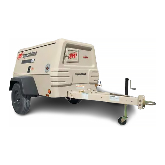
COMPRESSOR MODEL
P185WIR
XP185WIR
Revised (09-12)
( )
1
Advertisement

Related Manuals for Ingersoll-Rand P185WIR


Summary of Contents for Ingersoll-Rand P185WIR
- Page 1 This manual must be available to the personnel who operate and maintain this machine. Doosan purchased Bobcat Company from Ingersoll-Rand Company in 2007. Any reference to Ingersoll-Rand Company or use of trademarks, service marks, logos, or other proprietary identifying marks belonging...
- Page 2 QUALITY POLICY We will supply products and services that consistently meet the requirements of our customers and each other. CALIFORNIA Proposition 65 Warning Diesel engine exhaust and some of its constituents are known to the State of California to cause cancer, birth defects, and other reproductive harm.
- Page 3 Foreword Machine models represented in this manual may be used in various locations worldwide. Machines sold and shipped into European common market countries requires that the machine display the EC Mark and conform to various directives. In such cases, the design specification of this machine has been certified as complying with EC directives.
- Page 4 Nothing contained in this document is intended to extend any promise, warranty or representation, expressed or implied, regarding the Ingersoll--Rand products described herein. Any such warranties or other terms and conditions of sale of products shall be in accordance with the standard terms and conditions of sale for such products, which are available upon request.
- Page 5 TABLE OF CONTENTS SECTION 1 ....SAFETY SECTION 2 ....WARRANTY/REGISTRATION SECTION 3 ....NOISE EMISSION SECTION 4 .
- Page 6 IMPORTANT Remove hardware box from compressor toolbox. Open box and remove the bag containing NOTICE hardware, safety chains and assembly instructions. This machine may have been shipped from the factory Using the jack, raise the front of the unit so with the drawbar positioned upright.
- Page 7 SECTION 1- - SAFETY SAFETY PRECAUTIONS Compressed air must not be used for a feed to any form of breathing apparatus or mask. General Information The discharged air contains a very small percentage Ensure that the operator reads and understands the of compressor lubricating oil and care should be taken decals and consults the manuals before maintenance to ensure that downstream equipment is compatible.
- Page 8 This machine may include such materials as oil, diesel Use care to avoid contacting hot surfaces (engine fuel, antifreeze, brake fluid, oil/air filters and batteries exhaust manifold and piping, air receiver and air which may require proper disposal when performing discharge piping, etc.).
- Page 9 SAFETY LABELS Look for these signs on machines shipped to international markets outside North America, which point out potential hazards to the safety of you and others. Read and understand thoroughly. Heed warnings and follow instructions. If you do not understand, inform you supervisor. Hot Surface Corrosion risk Lifting point...
- Page 10 Read the Operation and Maintenance manual before operation or maintenance of this machine is undertaken. WARNING - - Maintain correct tire pressure. (Refer to the GENERAL INFORMATION section of this manual). WARNING: Consult the operation and maintenance manual before performing any maintenance. Rough Service Designation Wet Location Operation Do not stack...
- Page 11 Oil Drain km/h WARNING undertake Do not exceed the speed limit. maintenance on this machine until the electrical supply is disconnected and the air pressure is totally relieved. Read the Operation and Maintenance manual before operation or maintenance of this machine is undertaken Do not remove the Operating and Maintenance manual and manual holder from this machine.
- Page 12 Look for these signs on machines shipped to markets in North America, which point out potential hazards to the safety of you and others. Read and understand thoroughly. Heed warnings and follow instructions. If you do not understand, inform you supervisor. Indicates the presence of a hazard which WILL cause serious injury, death or property damage, if ignored.
- Page 13 km/h WARNING WARNING Improper operation of this equipment. Collapsing jackstand. Can cause serious injury or death. Can cause serious injury. Read Operator’s Manual supplied with this machine before operation or Insert locking pin completely. servicing. Excessive towing speed. Modification or alteration of this machine. Can cause serious injury or death.
- Page 14 CAUTION WARNING DO NOT USE ETHER. High pressure air. Can cause serious ENGINE DAMAGE WILL OCCUR. injury or death. This engine is equipped with an Relieve pressure before electric heater starting aid. removing filler plugs/caps, fittings or covers. NOTICE COOLANT FILL INSTRUCTIONS Adding: USE DIESEL Do NOT remove radiator cap.
- Page 15 SECTION 2 - - Warranty Ingersoll--Rand, through its distributor, warrants that each item of equipment manufactured by it and delivered hereunder to the initial user will be free of defects in material and workmanship for a period of three (3) months from initial operation or six (6) months from the date of shipment to the initial user, whichever occurs first.
- Page 16 Ingersoll- -Rand Platinum Drive Train Warranty (Optional) – Platinum drive train pertains to the Ingersoll-- Rand Engine and Airend combination. The earlier of sixty (60) months from shipment to, or the accumulation of 10,000 hours of service. The starter, alternator, fuel injection system and all electrical components are ex- cluded from the extended warranty.
- Page 17 GENERAL WARRANTY INFORMATION GENERAL WARRANTY Extended Coverage Portable Compressor Package 1 year/2000 hours Airend 2 years/4000 hours 5 years/10,000 hours Limited warranty, major components (refer to operator’s manual). Portable Genset 8KW, 11KW, 20KVA Package 1 year/2000 hours None thru 575KVA Generator 2 years/4000 hours None...
- Page 18 Extended Limited Airend Warranty Ingersoll--Rand Portable Compressor Division is pleased to announce the availability of extended limited airend warranty. Announcement of the extended warranty coincides with the introduction of PROSTECt Compressor Fluid. PROSTECt Compressor Fluid is an amber colored fluid specially formulated for Portable Compressors and is being provided as the factory filled fluid for all machines except ! XHP650/900/1070 models.
- Page 19 WARRANTY REGISTRATION Complete Machine Registration Machines shipped to locations within the United States do not require a warranty registration unless the machine status changes (i.e. change of ownership). Machines shipped outside the United States require notification be made to initiate the machine warranty.
- Page 20 WARRANTY REGISTRATION Selling Distributor Servicing Distributor Name Name Owner/User Name Address Address Address City City City County County County State State State Zip Code Zip Code Zip Code Telephone Telephone Telephone Complete the Applicable Blocks Owner/User Type of Business (check one only) Construction--Heavy Asphalt Contractor Coal Mining...
- Page 21 - - - - - - - - - - - - - - - - - - - - - - - - - - - - - - - - - - - - - - - - - - - - - - - - - - - - - - - - - - - - - - - - - - - - - - - - - - - - Book: 22305593 (8/03)
- Page 22 CALIFORNIA EMISSION CONTROL WARRANTY Exhaust Manifold • STATEMENT Turbocharger System • Miscellaneous hoses, clamps, connectors and • sealing devices used in the above systems. EMISSION RELATED SYSTEM DEFECT WARRAN- If failure of one of these components results in failure of another part, both will be covered by this warranty. Any Replacement part may be used for maintenance Ingersoll--Rand Company warrants to the initial owner or repairs.
- Page 23 Your emission control system may include parts such as the fuel injection system, air induction system. LIMITATIONS Also included may be hoses, belts, connectors and other emission--related assemblies. Where a warrantable condition exists, an authorized Ingersoll--Rand Company is not responsible for re- INGERSOLL--RAND Dealer will repair the heavy-- sultant damages to an emission related part or com- duty off--road engine at no cost to the owner including...
- Page 24 FUEL INJECTION PUMPS OR NOZZLES – Fuel in- MAINTENANCE RECOMMENDATION: jection pumps or nozzles are subject to tip wear as a Some Ingersoll--Rand Company non--road engines result to fuel contamination. This damage can cause are certified by the United States Environmental an increase in fuel consumption, the engine to emit Protection Agency and California Air Resource Board black smoke, misfire or run rough.
- Page 25 SECTION 3 - - NOISE EMISSION This section pertains only to machines distributed with- in the United States. WARNING TAMPERING WITH NOISE CONTROL SYSTEM PROHIBITED Federal law prohibits the following acts or the causing thereof: (1) The removal or rendering inoperative by any persons, other than for purposes of maintenance, repair, or re- placement, of any device or element of design incorporated into any new compressor for the purpose of noise control prior to its sale or delivery to the ultimate purchaser or while it is in use;...
- Page 26 NOISE EMISSION CONTROL MAINTENANCE LOG COMPRESSOR MODEL SERIAL NO. USER UNIT NO. UNIT IDENTIFICATION DEALER OR DISTRIBUTOR FROM WHOM PURCHASED: Engine Make & Model: Serial No.: Purchaser or Owner: Address: Date Purchased: The Noise Control Act of 1972 (86 Stat. 1234) prohibits tampering with the noise control system of any compressor manufactured and sold under the above regulations, specifically the following acts or the causing thereof: (1) the removal or rendering inoperative by any persons, other than for purposes of maintenance, repair, or replace- ment, of any device or element of design incorporated into new compressor for the purpose of noise control prior...
- Page 27 MAINTENANCE SCHEDULE ITEM AREA PERIOD Compressed Air Leaks As Detected Safety and Control Systems As Detected Acoustic Materials Daily Fasteners 100 hours Enclosure Panels 100 hours Air Intake & Engine Exhaust 100 hours Cooling Systems 250 hours Isolation Mounts 250 hours Engine Operation See Operator’s Manual Fuels &...
- Page 28 MAINTENANCE RECORD FOR NOISE EMISSION CONTROL AND EXTENDED WARRANTY ITEM NO. DESCRIPTION OF WORK HOURMETER MAINT/ LOCATION CITY/ WORK DONE BY READING STATE (NAME) INSPECT DATE Book: 22305593 (8/03)
- Page 29 ............P185WIR .
- Page 30 SECTION 5 - - OPERATION SETTING - - UP (ALL UNITS) BEFORE TOWING Place the unit in an open, well--ventilated area. • WARNING Position as level as possible. The design of these units permits a 15 degree sidewise limit on out-- of--level operation.
- Page 31 COMPRESSOR OIL LEVEL WARNING Check the compressor oil level in the sight glass located on the separator tank. NO SMOKING, SPARKS or OPEN FLAME near fuel. WARNING Always raise (or remove) jack for maximum ground clearance before towing. UTILITY PACKAGE SET- -UP (no running gear) This unit must be located on vehicle bed to allow ac- cess for normal servicing and maintenance.
- Page 32 CONTROL PANEL Controls (Standard) 12. Power Switch - - Rotate “ON” to activate systems prior to Starting. Rotate “Off” to stop engine. 19. Service Air Button - - After warm--up, PUSH. Provides full air pressure at the service outlet. Optional Controls 13.
- Page 33 Exercise extreme caution when using a booster battery to start. To jump start: Connect the ends of one BEFORE STARTING booster cable to the positive (+) terminals of each battery. Then connect one end of the other cable to the CAUTION negative (--) terminal of the booster battery and the other end to the engine block.
- Page 34 NOTICE UNITS WITH OPTIONAL DIAGNOSTICS LAMPS Do NOT wire around or bypass a shutdown sensor or NOTICE switch. None of the panel lamps should be glowing when ma- All units in this family of machines are protected by chine is operating. If they are, shut unit down and refer sensors or switches at the following locations: to Trouble Shooting Section.
- Page 35 P185WIR Speed and Pressure Regulator Adjusting Instructions FULL After Starting Unit The engine idle and full speed settings are set and sealed at the factory, and should not be adjusted. If equipped, push the SERVICE AIR but- Serious injury may result if the full speed is ton on the control panel, making certain increased.
- Page 36 SECTION 6 - - MAINTENANCE CAUTION COMPRESSOR OIL LEVEL Any unauthorized modification or failure to maintain this equipment may make it unsafe and out of factory Check the compressor oil level in the sight glass warranty. located on the separator tank. If performing more than visual inspections, disconnect battery cables and open manual blowdown valve.
- Page 37 To service the air cleaners on all units proceed as In the event the element is contaminated with dry dirt, follows: oil or greasy dirt deposits, and a new element is not Release cover latches, and remove cover. available, cleaning can be accomplished by washing, using the air cleaner element manufacturer’s recommendations.
- Page 38 Pulling on the tubing will cause the inner sleeve to with- draw and compress, thus tightening the connection. COMPRESSOR OIL COOLER The tubing can be withdrawn only while holding the The compressor lubricating and cooling oil is cooled sleeve against the fitting. The tubing can be removed by means of the fin and tube--type oil cooler, located and replaced numerous times without losing its seal- below the radiator.
- Page 39 Excessive grease in the hub or grease cap serves no 4. Lubricate the new filter gasket with the same oil purpose due to the fact that there is no way to force the being used in the machine. grease into the bearing. The manufacturer’s standard procedure is to thoroughly pack the inner and outer 5.
- Page 40 SCAVENGE LINE S In the compressor lubricating and cooling system, separation of the oil from the compressed air takes The scavenge line runs from the combined orifice/drop place in the receiver--separator tank. As the tube in the separator tank, to the orifice fitting located compressed air enters the tank, the change in velocity in the airend.
- Page 41 SCAVENGE LINE If the paint has faded or chalked, the use of a commercial grade, non--abrasive car wax may WARNING partially restore the color and gloss. Field Repair of Texture Paint High pressure air can cause severe injury or death from hot oil and flying parts.
- Page 42 MAINTENANCE SCHEDULE These time periods should be reduced if operating in extreme conditions (very hot, cold, dusty or wet). Daily Weekly Monthly 3 MOS . 6 MOS. 12 MOS. SMALL UNITS (P100- -P600) 250 hours 500 hours 1000 hours LARGE UNITS (HP600- -P1600) 500 hours 1000 hours 2000 hours...
- Page 43 SECTION 7 - - Portable Compressor Fluid Chart Refer to these charts for correct compressor fluid RATED OPERATING PRESSURE required. Note that the selection of fluid is dependent on 350 PSI 100 - - 300 PSI the design operating pressure of the machine and the 125_F ambient temperature expected to be encountered 50_C...
- Page 44 Section 8 - - Trouble Shooting INTRODUCTION B. Do The Simplest Things First Trouble shooting for a portable air compressor Most troubles are simple and easily corrected. is an organized study of a particular problem or example, most complaints are “low capacity” which may series of problems and a planned method of be caused by too low an engine speed or “compressor procedure for investigation and correction.
- Page 45 TROUBLE SHOOTING CHART Bold Headings depict the COMPLAINT - - Subheadings depict the CAUSE Note: Subheadings suggest order to follow in cause of troubleshooting. Excessive Compressor Oil Temperature: Short Air Cleaner Life: Ambient Temperature Too High Out of Level > 15 degrees Dirty Operating Conditions Low Oil Level Inadequate Element Cleaning...
- Page 46 Unit Shutdown: Won’t Start/Run: Out of Fuel Low Battery Voltage Compressor Oil Temp. Too High Blown Fuse Engine Oil Pressure Too Low Malfunctioning Start Switch Broken Engine Fan Belt Clogged Fuel Filters Loose Wire Connection Out of Fuel Defective Switches Compressor Oil Temp.
- Page 47 SECTION 9 4IRI8N ENGINE CONTENTS FOREWORD EXTERNAL VIEW : 4IRI8N GENERAL INFORMATION: 4IRI8N Main data and specifications Engine identification Ingersoll--Rand engine after sales support EMISSION CONTROL LABEL FUEL, LUBRICANT, AND COOLANT Fuel Lubricant Coolant OPERATION Check before operation Check and operation after start-- up Operation and care of a new engine PERIODICAL INSPECTION AND MAINTENANCE...
- Page 48 FORWORD The INGERSOLL- - RAND industrial diesel engines are a product of long years of experience, advanced technology, and up- - to date production facilities. INGERSOLL- - RAND takes great pride in the superior durability and operating economy of these engines. In order to get the fullest use and benefit from your engine, it is important that you operate and maintain it correctly.
- Page 49 EXTERNAL VIEWS DIESEL ENGINE Engine External View -- Model 1. Lifting eye 25.Rocker arm cover 2. Cooling water pump 26.Filler port (engine oil) 3. Cooling fan 4. Crank shaft V- -pulley 5. V- -belt 6. Filler port (engine oil) 7. Drain plug (engine oil) 8.
- Page 50 EPA CERTIFIED ENGINE DATA and SPECIFICATIONS GENERAL INFORMATION Model: 4IRI8N Engine model name 4IRI8N Engine type Vertical inline water cooled diesel engine Combustion type Direct injection No. of cylinders - - bore x stroke. mm 4- -98x110 Engine displacement L 3.319 Compression ratio 18.1:1...
- Page 51 ENGINE LABEL (FOR EPA) EMISSION CONTROL LABEL Emission control label is attached on the “top of rocker arm cover.” The location of emission control label attached on the engine may vary depending on the engine specification The following is the sample of a label required for engine emission control information, along with location. * Engine family name as assigned by EPA and ARB identifying engine family group 3YDXL1.33M3N and this identifies 3 YDX L 1.33 M 3 N Method of air aspiration...
- Page 52 FUEL, LUBRICANTS, and COOLANT If refueling is done from an oil drum directly, ensure that it has been FUEL kept stationary to allow any dust, sediment or water to settle at the bottom. Do not draw fuel direct from the bottom of the drum to prevent Fuel Selection pickup of any settled foreign material.
- Page 53 NOTE LUBRICANT Using a mixture of different brands or quality of oils will adversely affect The quality of engine oil can affect engine performance, startability the original oil quality; therefore, never mix different brand or different and engine life. type oils. Use of unsuitable engine oil will result in piston ring, piston and Do not use API, CA, CB grade and reconstituted engine oil cylinder seizure and accelerate surface wear causing increased oil...
- Page 54 ENGINE OPERATION Remove filler cap (yellow coloured) on the rocker arm cover side of engine. Engine Exhaust Gas Caution (Carbon Monoxide) Fill with engine oil up to the upper limit on the dipstick. WARNING Manually tighten the filler cap. Do not use a tool such as pliers to tighten Do not breathe exhaust gas because it contains carbon monoxide, which by itself has no color or odor.
- Page 55 Battery Cable Connection CHECKS AND OPERATION AFTER START- - UP Check the battery cable connections for looseness or corrosion. A Check after the Engine Start- - up loosened cable connection will result in hard engine starting or insufficient battery charge. The battery cables must be tightened Check the following items in the engine warming- -up operation.
- Page 56 Make sure the fan belt is not broken, or off the pulley, and that the fan OPERATION AND CARE OF A NEW ENGINE turns when the engine is started. If the engine coolant level in the reserve tank is low, look for leaks at the radiator hoses and Your Ingersoll- -Rand engine is carefully tested and adjusted in the connections, radiator, and water pump.
- Page 57 ENGINE MAINTENANCE SCHEDULE IMPORTANT: Establish a periodic check plan according to the operating conditions and make sure to conduct checks at specified intervals. Otherwise, malfunctioning may occur to shorten the engine life. As special knowledge and skill are required for items marked with F, consult your local Ingersoll- - Rand branch or distributor. f: Check Z: Replace F: Contact your dealer...
- Page 58 PERIODICAL INSPECTION AND MAINTENANCE Inspection after initial 50 hours operation (1) Replacing the engine oil and engine oil filter (1st time) When the engine oil is still hot, be careful with a splash of engine oil which may cause burns. Cool the engine to replace engine oil until the engine oil becomes warm.
- Page 59 (2) Checking and adjusting cooling fan V- - belt S ”Used V- -belt” refers to a V- -belt which has been used on a running engine for 5 minutes or more. When there is not enough tension in the V- -belt, the V- -belt will slip making it impossible for the alternator to generate power and cooling Install the new V- -belt adjusting the deflection to the value in the table water pump and cooling fan will not work causing the engine to...
- Page 60 Inspection every 50 hours operation Governor Control Seals As the governor is precisely adjusted, most of the controls are sealed, (1) Draining of the fuel tank (NOT 7/26) please do not break them. Should any adjustment be necessary, 1) Prepare a waste oil container. contact your local Ingersoll- -Rand branch or distributor.
- Page 61 Inspection every 250 hours operation S If the engine cranking speed is so slow that the engine does not start up, recharge the battery. (1) Replacing the engine oil and engine oil filter (2nd time and S If the engine still will not start after charging, replace the battery. after) S Remove the battery from the battery mounting of the machine unit Replace the engine oil every 250 hours operation from 2nd time and on.
- Page 62 (3) Checking the governor lever and accelerating device. Screw the new element onto the head firmly by hand. The governor lever and accelerating devices (accelerating lever, pedal. Follow the “fuel system air bleeding” procedure. see “inspection after etc.) of the machine unit are connected by a fixed linkage to a every 50 hours operation”...
- Page 63 Inspection every 500 hours operation EPA allows to apply maintenance schedule for emission related parts as follow. (1) Replacing the air cleaner element Replace the air cleaner element periodically even if it is not damaged Check Fuel Valve Adjust, cleaning and or dirty.
- Page 64 Note: L This is a recommended maintenance. The failure to perform this maintenance item will not nullify the emission warranty or limit recall liability prior to the completion engine useful life. Ingersoll- -Rand, however, urges that recommended maintenance service is performed at the indicated intervals. EXPLANATION OF MAINTENANCE SCHEDULE The following is a brief explanation of the services listed in the preceding Engine Maintenance schedule.
- Page 65 This item contains a simple troubleshooting. When a failure takes place on your Ingersoll- -Rand engine, diagnose the cause referring this troubleshooting. Should the cause of failure not be detected or you are unable to manage the failure, consult your machine supply source or nearest Ingersoll- -Rand engine service outlet.
- Page 66 Unstable engine running Crack in injection pipe. Injection nozzle failure. Unstable low idling Engine stop solenoid return failure. Uneven compression pressure between cylinders. Incorrect high idle speed Incorrect control lever adjustment. adjustment. Governor internal malfunction. Engine hunting in medium speed Governor spring deteriorated.
- Page 67 Low engine output Incorrect injection timing Too far advanced. Too far retarded. Injection nozzle malfunction Incorrect injection pressure. Incorrect spray condition. Incorrect injection pump adjustment Lack of fuel in tank. Insufficient fuel supply to the Air in injection pump. injection pump Fuel filter clogged.
- Page 68 Improper exhaust Clogged air cleaner. Damaged injector nozzle. Excessive black smoke Wrong injector nozzle. Injection timing incorrect. Excessive injection volume. Incorrect fuel. Water mixing in fuel Excessive white smoke Low compression pressure. Injection timing incorrect. Low coolant temperature Faulty turbocharger Battery over discharge Low electrolyte level Crack in battery body.
- Page 69 SECTION 11 - - PARTS LIST...
Need help?
Do you have a question about the P185WIR and is the answer not in the manual?
Questions and answers