
Related Manuals for Atlas Copco Dynapac F3030C


Summary of Contents for Atlas Copco Dynapac F3030C
- Page 1 OPERATION & MAINTENANCE Paver Finisher Dynapac F3030C 02-0515 4812273381 (A4) Keep for later use in document compartment Valid for:...
- Page 2 www.atlascopco.com...
-
Page 3: Table Of Contents
Table of Contents Preface ………………………………………………………………………….…….1 General safety instructions…………………………..……………………………….2 Laws, guidelines, accident prevention regulations………………………………2 Warnings………………………………………………………………………………3 Prohibitive symbols…………………………………………………………………..5 Protective equipment………………………………………………………………...6 Environment protection………………………………………………………………7 Fire prevention………………………………………………………………………..7 Additional information………………………………………………………………..8 Guarantee conditions…………………………………………………………………9 Residual risks………………………………………………………………………...10 Sensibly predictable incorrect usage………………………………………………11 Correct use and application……………………………………………………….1 Vehicle description ..................1 Application ......................1 Description of assemblies and functions ……...........2 Vehicle......................4 Construction ....................4... - Page 4 5.12 Screed lifting device ..................15 5.13 Electrical system ...................16 5.14 Permissible temperature ranges ..............16 Location of instruction labels and identification plates ........17 Identification label for the paver finisher ............19 EN standards ....................20 Continuous sound pressureF3030C, Cummins QSB 6.7-C190 ....20 Operating conditions during measurement ........... 20 Measuring point configuration ..............
- Page 5 Remote control, left side...............28 Remote control, right side..............32 Operation……………………………………............1 Display terminal description................1 Welcome interface..................1 Main interface.....................2 Calibration interface..................4 Electrical system input parameter monitoring page1........5 Electrical system input parameter monitoring page2........6 Propulsion system output parameters and faults monitoring page………...7 Electrical system faults monitoring page.............8 Engine parameters page1................9 Engine parameters page2.................10 Engine fault display page................11...
- Page 6 Paving thickness indicator.................12 Auger lighting (O) ..................12 Auger height adjustment ratchet...............13 Auger height indicators ................13 Sensor rod / sensor rod extension.............14 Conveyor limit switches - conventional version.........16 Ultrasonic auger limit switches (left and right) - PLC version.....17 Pressure control valve for screed charging / relieving………....18 Pressure control valve for paving stop with relieving.........18 Manometer for screed charging / relieving..........18 Central lubrication system (O) ..............19...
- Page 7 Driving and stopping the paver finisher.............17 1. 3 Preparation for paving...................18 Separator fluid...................18 Screed heater system................18 Direction marks..................18 Loading / Conveying material..............21 1. 4 Starting for paving..................23 1. 5 Checks during paving..................24 Paver function...................24 Quality of the layer..................24 1. 6 Paving with “screed control at paving stop”...
- Page 8 2. 1 Height adjustment...................2 Grain sizes up to 16mm................2 Grain sizes > 16 mm...................2 2. 2 Mechanical adjustment with ratchet..............3 2. 3 Hydraulic adjustment..................3 2. 4 Height adjustment for large working widths / with brace........4 Auger extension....................5 3. 1 Mounting the auger shaft extension and chute plate........6 3.
- Page 9 Connecting diagram..................34 Limit switch....................35 6. 1 Auger limit switches (left and right) – mouting the PLC version....35 Screed......................36 Electrical connections..................36 Maintenance....................1 Notes regarding safety…………………..………………………………………1 Maintenance review………………………………………………………….….1 Maintenance review…………………………………………………………….…1 Maintenance – conveyor…………………………………………………..……1 Maintenance – conveyor…………………………………………………….……1 Maintenance intervals…………………………………………………………..…2 Points of maintenance……………………………………………...………..……3 Chain tension, conveyor………………………………………………..…3 Check / replace conveyor chain…………….………………………….……..4 Replace bottom plate…………….…………………………………..………...4 Replace conveyor deflector………….…………….……………..……………5...
- Page 10 Check tightening (6) ...................9 Mounting and inspection Outer auger bearing – Check tightening (7) ..........9 Auger blade (8) ..................10 F 50 Maintenance – engine assembly……………………………………………….1 Maintenance – engine assembly..............1 1. 1 Maintenance intervals..................2 1. 2 Points of maintenance...................4 Engine fuel tank (1) ..................4 Engine lube oil system (2) ..............
- Page 11 Rollers (3) ....................7 Planetary gear (4) ..................8 Screw connections..................9 Maintenance — Electrical system…….…………………………………………1 Maintenance - electrical system……………………………………………..…….1 Maintenance of batteries……………………….…………..…………………….2 Fuses and relays…………………………………………………………………..2 Maintenance – lubricating point…………………………..………………………1 Maintenance………………………………………………………………..….……..1 Maintenance – Points of lubrication…………….………………………….….……2 Maintenance interval…………………………………………………………………3 Maintenance points……………………………..……………………………………4 Central lubrication system……………………………………..…………...……5 Check filling level…………………………………………………..………..……5 Top up lubricant tank…………………………………………………………..…5 Bleed central lubrication system………………………………………….…..…6...
- Page 12 Lubricants and operating substances.............1 Capacities.......................3 Lubricant specifications..................4 Engine oil.......................4 Coolant......................4 Pump distribution gear oil ................4 Drive unit planetary gear oil................4 Auger drive planetary gear oil ................4 Auger box gear oil..................4 Grease......................4 Hydraulic system....................5...
-
Page 13: Preface
V Preface If the vehicle is to be operated safely, the information provided in these operating instructions will be required. The information is provided in a concise, clearly instructed form. The individual chapteres are arranged in alphabetical order, and every chapter starts with page 1. The individual pages are identified by the chapter letter and the page number. -
Page 14: General Safety Instructions
General safety instructions 1.1 Laws, guidelines, accident prevention regulations The locally applicable laws, guidelines and accident prevention regulations must always be observed, even if these are not expressly named here. The user himself/herself is responsible for compliance with the resulting regulations and measures! The following warnings, prohibitive symbols and instructive symbols indicate dangers for persons, the vehicle and the environment due to residual risks when... -
Page 15: Warnings
1.2 Warnings Warning on a dangerous area or hazard! Failure ot observe the warings can result in life-threatening injuries! Warning on danger of being pulled in! In this working area/on this element there is a danger of being pulled in by rotating or conveying elements! Only carry out activities with elements switched off! Warning on dangerous electrical voltage! All maintenance and repair work on the screed’s electrical... - Page 16 Warning on danger of falling! Warning on dangers posed by batteries! Warning on hazardous or irritating substances! Warning on substances which constitute a fire hazard! Warning on gas bottles!
-
Page 17: Prohibitive Symbols
Prohibitive symbols Opening/walking on /reaching in/ carrying out/setting up are prohibited during operating or while the drive engine is running! Do not start engine/drive! Maintenance and repair work may only be carried out with the disel engine shut down Spraying with water is prohibited! Extinguishing with water is prohibited! Unauthorised maintenance is prohibited! Only qualified experts may conduct maintenance! -
Page 18: Protective Equipment
1.4 Protective equipment Locally applicable regulations may require the wearing of various safety equipment! Always observe these regulations! Wear safety goggles to protect your eyes! Wear suitable head protection! Wear suitable hearing protection to protect your hearing! Wear safety shoes to protect your feet! Always wear close-fitting work clothing! Wear a warning vest to be seen in time to avoid accident! Wear respiratory equipment if breathing air is contaminated! -
Page 19: Environment Protection
1.5 Environment protection The locally applicable laws, guidelines and accident prevention regulations for the proper recycling and disposal of waste must always be observed, even if these are not expressly named here. Water-endangering substances like: - Lubricants (oil, grease) - Hydraulic oil - Disel fuel - Coolnat - Cleaning liquids... -
Page 20: Additional Information
1.7 Additional information Also observe the manufacturer’s documentation and additional documentation! For example, the maintenance instructions of the engine manufacturer Description / depiction applicable when equipped with gas heater! Description / depiction applicable when equipped with electric heater! -
Page 21: Guarantee Conditions
Guarantee conditions The guarantee conditions are included in the scope of supply of the machine. This contains a complete specification of the valid conditions. The guarantee becomes null and void if damage occurrs through malfunctions caused by improper use and incorrect operation. -
Page 22: Residual Risks
Residual risks These are risks that remain even if all possible measures and safety precautions have been taken to help minimise dangers (risks) or to reduce their probability and scope to zero. Residual risks in the form of - Danger to life and limb of persons at the machine - Danger to the environment posed by the machine - Damage to property and restricted output and functionality of the machine... -
Page 23: Sensibly Predictable Incorrect Usage
4 Sensibly predictable incorrect usage Every kind of sensibly predictable incorrect usage of the machine constitutes misuse. Incorrect usage makes the manufacturer's warranty null and void: the operator bears sole responsibility. Sensibly predictable incorrect usage of the machine includes: - presence in the danger zone of the machine - transporting persons - leaving the operator's platform while the machine is operating - removing protection or safety devices... - Page 24 V 12...
-
Page 25: A Correct Use And Application
A Correct use and application The “Guidelines for the Correct Use and Application of Paver Finishers” compiled by Dynapac are included in the scope of delivery for the present machine. The guidelines are part of the present operating instructions and must always be heeded. National regulations are fully applicable. -
Page 27: B Vehicle Description
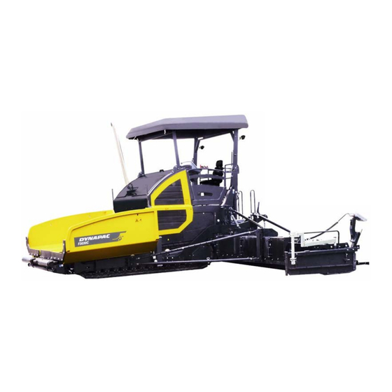
B Vehicle description 1. Application The Dynapac F3030C paver finisher is a paver finisher with a caterpillar drive which is used for laying bituminous mixed material, roll-down or lean-mixed concrete, track-laying ballast, stabilized soil and macadam for foundations for paving. -
Page 28: Description Of Assemblies And Functions
2. Description of assemblies and functions... - Page 29 Item Designation Material compartment(hopper) Push roller crossbar for truck docking Tube for sensor rod (direction indicator) and holder for leveling shoe Caterpillar drive Levelling cylinder for paving thickness Traction roller Crossbeam pull bar Paving thickness indicator Crossbeam Travel drive of the caterpillar drive Auger Screed Operator ' s platform and double rotatable seats...
-
Page 30: Vehicle
2. 1 Vehicle Construction The paver finisher has a welded steel frame on which the individual components are mounted. The caterpillar drives compensate uneven areas on the ground; the suspension of the attached screed additionally helps to attain high paving precision. The continuously adjustable hydrostatic travel drive allows the speed of the paver finisher to be matched to all work conditions. - Page 31 Engine: The paver finisher is driven by a water cooled diesel engine. For further details see the technical data and the engine’s instruction manual. Drive unit:Both caterpillar drives are directly driven by separate drives. They operate directly, without any drive chains which require maintenance or servicing. The tension of the caterpillar chains can be readjusted using tensioners.The height of the paver finisher chassis at the front area can be adjusted with hydraulic cylinders connecting the drive unit and the chassis, this can fit the material truck...
- Page 32 Material transfer: The paver finisher is equipped with two conveyors driven separately that transfer the material from the hopper to the augers. By scanning the filling height during the paving procedure and monitoring via conveyor sensors, the transfer amount or speed is regulated fully automatically. The drive is reversible (O).
- Page 33 The screed's approach angle can be changed using the eccentric adjustment facility on the crossbeam. Depending on the paving condition requirements, the crossbeam can be moved backwards or forwards. This adjustment enlarges or reduces the material space between the auger and screed.
-
Page 34: Danger Zones
3 . Danger zones In these vehicle working areas, there may be a risk of drawing in or crushing during normal operation caused by rotating and conveying elements, or by components in motion! Danger of being pulled in! Danger of crushing! -
Page 35: Safety Devices
Safety devices... - Page 36 Item Designation Hopper transport safeguard Screed lock, mechanical / hydraulic (O) Main switch Emergency stop button Horn Ignition key Lights Protective roof latch (O) Fire extinguisher (O) Side cover support Indicator lamp – screeds retract / extend ** Located on both sides of the vehicle Safe operation is only possible if the control and safety devices are functioning perfectly and if the protective equipment is fitted correctly.
-
Page 37: Technical Data, Standard Configuration
5. Technical data, standard configuration 5. 1 Dimensions (all dimensions in mm) For screed technical data, refer to the screed operating instructions. B 11... -
Page 38: Allowed Angle Of Rise And Slope
5. 2 Allowed angle of rise and slope Before operating your vehicle in an inclined position (gradient, slope, lateral inclination) which is above the specified limit value, please consult the customer service department for your vehicle! 5. 3 Permissible approach angle B 12... -
Page 39: Weights F3030C (All Weights In T)
5. 4 Weights F3030C (all weights in t) Approx. 18.5t Paver finisher without screed Approx. 20.5t Paver finisher with screed: R300DTV With extension parts for max.working width, Approx. 25.5t additionally max.: Approx. 22.3t Paver finisher with screed: V6030TV With extension parts for max.working width, Approx. -
Page 40: Travel Drive/Traction Unit
5.6 Travel drive/traction unit Hydrostatic drive, continuously Drive controllable Two separately driven caterpillar drives Drive unit with rubber grouser chains Turning capacity Turning on the spot See above Speed 5.7 Engine F3030C Cummins QSB 6.7-C190 / Make / type DCEC QSB 6.7-C190 Version 6-cylinder diesel engine (water-cooled) Performance... -
Page 41: Material Transfer
5.10 Material transfer Type Dual conveyor belt Width 2 x 600 mm Left and right auger separately Conveyors Drive Hydrostatic, switch controllable Fully automatic via mechanical conveyor Conveying volume controller limit switches 5.11 Material distribution F3030C Auger diameter 430mm, 380mm Hydrostatic central drive, continuously controllable Independently of the conveyor... -
Page 42: Electrical System
5.13 Electrical system On-board voltage 24 V Batteries 2 x 12 V, 100 Ah Generator (O) 5.14 Permissible temperature ranges Operation -5°C / +50°C Storage -5°C / +50°C B 16... -
Page 43: Location Of Instruction Labels And Identification Plates
6. Location of instruction labels and identification plates B 17... - Page 44 - At the end of work, allow the engine to idle for at least 5 minutes. Remove the ignition key after switching off the engine. 28 Label "Main battery switch" 29 Label " Engine oil " 30 Label " Diesel oil " 31 Label "Atlas Copco" B 18...
-
Page 45: Identification Label For The Paver Finisher
6. 1 Identification plate for the paver finisher Item Designation Paver finisher type Year of construction Serial number of the paver finisher series Max. permissible operating weight, incl. all extension parts, in kg Max. permissible load on the front axle, in kg Max. -
Page 46: Standards
7. EN standards 7. 1 Continuous sound pressure F3030C, Cummins QSB 6.7-C190 / DCEC QSB 6.7-C190 The operator always must use ear protection. The emission value at the ear of the driver varies depending on the materials used for paving and may even rise above 85 dB (A). -
Page 47: C11 Transportation
C11 Transportation Satety regulations for transportation Accidents can happen when the paver finisher and screed are not properly prepared for transportation or when transportation is carried out improperly! Reduce both the paver finisher and the screed to their basic widths. Remove all protruding parts (such as the automatic leveling system,auger limit switch, aprons, etc.). -
Page 48: Transportation On Low-Bed Trailers
Transportation on low-bed trailers Reduce the paver finisher and the screed to their basic widths; also remove any attached side plates. The maximum approach angle is indicated in the section entitled “Technical data”! Check the fill level of the operating substances so that these do not escape when driving on an incline. - Page 49 Operation Buttons - Close the hopper lids. - Engage both hopper transport safeguards. 1 = Locking handle 2 = Locking latch 3 = hopper - Lift the screed. - Turn the preselector to “zero”. - Extend levelling cylinders completely. - Set the drive lever to centre position.
-
Page 50: Driving Onto The Low-Bed Trailer
2.2 Driving onto the low-bed trailer Make sure that there are no persons in the danger area during loading. - Use the work gear and low travelling speed to drive onto the low-bed trailer. - Lower the screed onto wooden blocks on the low-bed trailer. - Switch off the paver finisher. -
Page 51: After Transportation
2.4 After transportation - Remove the attachment devices. - Raise the protective roof (O): See section entitled “Protective roof”. For a paver finisher without roof: - Mount the exhaust extension pipe. - Lift the screed to the transportation position and secure it. - Start the engine and drive from the trailer at a low travelling speed. -
Page 52: Protective Roof
3 Protective roof 3.1 Simple roof 1=Gas spring 2=Locking device for raising / lowering the roof 3=Locking device for raising the roof / working condition - Raise the roof: release the locks (2) on both sides of the roof, push the roof forwards to its uppermost position, and secure the locking devices (3) &... -
Page 53: Fibre Glass Roof
3.2 Fibre glass roof (O) The fibre glass roof can be raised and lowered with a manual hydraulic pump. The exhaust pipe is lowered or raised together with the roof. - Remove the lower section of the pump lever (1) from the storage compartment, and connect to the upper section using a pipe (2). -
Page 54: Transportation
4 Transportation Reduce the paver finisher and the screed to their basic widths; also remove any attached side plates. 4.1 Preparations - Prepare the paver finisher for transportation (see chapter D). - Remove all overlaying or loose parts from finisher and screed (see also Operating instructions for the screed). - Page 55 Operation Buttons - Close the hopper lids. - Engage both hopper transport safeguards. 1 = Locking handle 2 = Locking latch 3 = hopper - Lift the screed. - Turn the preselector to “zero”. - Extend levelling cylinders completely. - Set the drive lever to the centre position.
-
Page 56: Driving Mode
4.2 Driving mode Operation Buttons - Set the fast / slow switch to “Hare” if necessary. - Turn the drive lever to maximum. - Set the speed potentiometer to maximum. Press the emergency stop button when a dangerous situation arises! C11 10... -
Page 57: Loading By Crane
5 Loading by crane Use only lifting gear that can bear the load. (See chapter B for weights and dimensions). Attachment and loading equipment must meet the conditions of the applicable accident prevention regulations! The vehicle’s centre of gravity is dependent on the screed which is mounted. Four lifting eyes (1, 2) are provided for loading the vehicle with a crane. - Page 58 - Secure vehicle wherever it is parked up. - Engage the transport safeguards. - Remove any attachments and extension parts from the paver finisher and the screed until the basic width is attained. - Take off all protruding or loose parts and the gas bottles of the screed heater (see chapter E and D).
-
Page 59: Towing
6 Towing Heed all regulations and apply all safety measures applicable for towing heavy construction machines. The towing vehicle must be capable of securing the paver finisher, even on slopes. Use only approved tow bars! If necessary, remove any attachments and accessories from the paver finisher and the screed until the basic width has been attained. - Page 60 Two high-pressure cartridges (6) are located on both of the travel drive pumps (5). The following activities must be carried out to activate the towing function: - Loosen lock nuts (7) three turns. On completion of the towing process, restore the initial status. - Attach the towing bar to the coupling (8) located in the bumper.
-
Page 61: Safely Parking The Vehicle
7 Safely parking the vehicle When the paver finisher is parked at a location accessible to the public, it must be secured in such a way that unauthorised persons playing children cannot damage the vehicle. — Pull off the ignition key and the main switch (1) and take it with you. - Page 62 C11 16...
-
Page 63: D11 Operation
D11 Operation 1.Safety regulations Starting the engine, the travel drive, the conveyor, the auger, the screed or the lifting devices can cause injuries or even the death of persons. Make sure before starting any of these devices that no-one is working at, in or beneath the paver finisher or within its danger area! Do not start the engine or do not actuate any controls when this is expressly forbidden! -
Page 64: Controls
2.Controls 2.1 Operating panel In accordance with relevant stipulation, all auto switches which may cause risks (e.g. conveyor, auger manual and automatic functions) should be placed at stop position (middle position), otherwise, engine could not start. Item Designation Brief description Pushbutton function: - Left auger manually or automatically conveying... - Page 65 mode equals to the highest speed in “AUTO” mode. To work in “AUTO” mode, drive lever must be put into forward postion. Press in case of emergencies indicate when vechicle starts to move! Horn The horn can also be used to communicate acoustically with truck deliver...
- Page 66 Swivel the lever to the right, paver drive speed increases. Travel drive preselector For setting the maximum speed that can be reached when drive lever is at its top. Swivel the lever to the right, paver vibration speed increases. For setting the Vibration preselector maximum speed that can be reached when vibration lever is...
- Page 67 D11 5...
- Page 68 Item Designation Brief description Switching on the paver finisher, forward or reverse can be regulated by drive lever. Zero position: engine can start; engine at idling speed; no travel drive -Through releasing the interlock switch, swivel the drive lever to Drive lever different working position.
- Page 69 leveling cylinder in AUTO mode, screed floating, screed loading / unloading, paver finisher break release. Reverse position: paver finisher break release. To activate the ignition voltage by turning the key. -Switch off by turning the key back to its starting position. After energizing, screen and control panel will take some time to inspect and load the...
- Page 70 forward postion. Swivel the lever to the right, engine speed increases. For setting the maximum speed that Engine speed preselector can be reached when lever is at its top. D11 8...
- Page 71 D11 9...
- Page 72 Item Designation Brief description Swivel the lever to the right, Screed vibration speed paver vibration speed potentiometer increases. For setting the maximum speed that can be reached when lever is at its top. Activate the function, central lubrication starts to work. Close the button, central Central lubrication button lubrication system closed.
- Page 73 button again Avoid dazzling other road users! Switch ON the rear working lights Working lights, rear Switch OFF by pressing the ON / OFF button again Avoid dazzling other road users! Pushbutton function: -Activate screed vibration (“AUTO” or “MANUAL”) For triggering screed vibration, screed vibration switch must be switched to “AUTO”...
- Page 74 accidents! - The emergency stop button does not shut off the gas heater system.(o) Close the main shut-off valve and the valves on the bottles by hand! - To restart the engine, the button must be pulled out again! D11 12...
- Page 75 D11 13...
- Page 76 Item Designation Brief description Pushbutton function: -Hopper open or close. This button with reset function. Engage the switch upward, both side hopper close. Is required when paving in spaces where there is only Hopper expand / collapse switch limited space at one side or when obstacles obstruct truck unloading.
- Page 77 Pushbutton function: -Button is at upper position: Lift the right side leveling cylinder. Right levelling cylinder switch -Button is at lower position: Lower the right side leveling cylinder. AUTO / MANUAL leveling cylinder switch must be switched to “MANUAL” for this function.
- Page 78 Paver finisher can achieve the highest transport speed. - Button is at lower position: (tortoise) Paver finisher is set to normal operating speed. D11 16...
- Page 79 D11 17...
- Page 80 Item Designation Brief description Pushbutton function: - Left conveyor manually or automatically conveying front outwards. For triggering conveyor function, conveyor pushbutton Left conveyor control switch function must be switched to “AUTO” or “MANUAL”. Conveyor speed under “MANUAL” mode equals to the highest speed under “AUTO”...
- Page 81 forward postion. Speed of conveyor is controlled by limit switch inside material level sensor. To avoid material overload, conveyor would stop working when material level exceeds limit. On actuation, note danger zones of moving parts of the vechicle! Pushbutton function: This button is two gear unresettable button.
- Page 82 Botton at right position: the left side of telescoping screed retract inwards; Botton at left position:the right side of telescoping screed extend to the outside; Right screed extend/retract switch Botton at right position: the right side of telescoping screed retract inwards. D11 20...
- Page 83 D11 21...
- Page 84 Item Designation Brief description Pushbutton function: It is a resettable button -Button is at upper position: Screed can be lifted. -Button is at lower position: Screed can be lowered. To activate screed loading / Screed lift / lower button deloading function, drive lever must be set at forward position.
- Page 85 - Right conveyor manually or automatically conveying front outwards. For triggering conveyor function, conveyor pushbutton function must be switched to “AUTO” or “MANUAL”. Conveyor speed under “MANUAL” mode equals to the highest speed under “AUTO” mode. To work under “AUTO” mode, drive lever must be put into forward postion.
- Page 86 Item Designation Brief description See from display section; select Button 4 function on display the menus assigned in display area to switch commands. Display See from display section Lights up when a serious error Error message has occurred on the engine. Switch off the drive engine “Serious error”...
- Page 87 at the sametime. Lights up for a few seconds once the ignition has been switched on for checking purposes. Indicates that there is a drive engine fault. Depending on the type of fault, the vehicle can temporarily continue to be operated or, in the case of serious faults, should be shut down immediately to prevent...
- Page 88 once the ignition has been switched on for checking purposes. Must go out after starting when Battery charge indicator engine revs up. (red) - If the light does not go out, switch off the engine. D11 26...
-
Page 89: Special Functions
2.2 Special functions Reversible conveyor The conveyor’s direction can be reversed in order to slightly reverse any material which may be positioned just in front of the auger. In this case, material loses to be avoided during transportation. - Turn the reverse function switch (50) to “Reverse” position (Forward rotation position is Down Arrow;... -
Page 90: Remote Control
3.Remote control Before operating the remote control, make sure cables have the correct connections, emergency stop button is pulled out; before connecting the remote control, shut down batteries to ensure safety. Remote control, left side Item Designation Brief description In the case of an emergency (danger to persons, possible collision, etc.), press in the button! - Page 91 longer possible! Danger of accidents! - The emergency stop button does not shut off the gas heater system.(o) Close the main shut-off valve and the valves on the bottles by hand! - To restart the engine, the button must be pulled out again! Press the button, left leveling cylinder starts to ascend, when...
- Page 92 Remote control, left side Item Designation Brief description To activate this function, left auger control switch on control panel must be switched to “AUTO”. Left auger manually or automatically conveying outwards. For triggering auger function, Left auger control switch auger pushbutton function must be switched to “AUTO”...
- Page 93 Botton at left position: the left side of telescoping screed extending to the outside; Left screed extend/retract switch Botton at right position: the left side of telescoping screed retract inwards; When auger is under “MANUAL” mode, use this Left auger speed preseletor, button to control auger speed;...
-
Page 94: Remote Control, Right Side
Remote control, right side Item Designation Brief description In the case of an emergency (danger to persons, possible collision, etc.), press in the button! - Pressing the emergency stop button switches the engine, the drives and the steering system off. Emergency stop button Making way, lifting the screed or other actions are then no... - Page 95 and the valves on the bottles by hand! - To restart the engine, the button must be pulled out again! Press the button, right leveling cylinder starts to decend, when Right leveling decend, manual reach to suitable height release mode the button, cylinder stop moving.
- Page 96 Remote control, right side Item Designation Brief description Botton at left position:the right side of telescoping screed extend to the outside; Right screed extend/retract switch Botton at right position: the right side of telescoping screed retract inwards. To activate this function, right auger control switch on control panel must be switched to “AUTO”.
- Page 97 be switched to “AUTO” or “MANUAL”. Auger speed under “MANUAL” mode equals to the highest speed under “AUTO” mode. To work under “AUTO” mode, drive lever must be put into forward postion. When material is unsufficient, Right conveyor pushbutton, press this button for material manual conveying, release the button when material is sufficient.
- Page 98 D11 36...
-
Page 99: D21 Operation
D21 Operation 1. Display terminal description Welcome interface Welcome interface will automatically appear after power supply, and switch to display main interface after 3 seconds. D21 1... -
Page 100: Main Interface
Main interface Enter main interface, system will display machine errors messages. Press button SOFT1 to cancel them,and then scroll to normal display. Machine errors messages include errors messages of engine, as well as electrical system. For specific errors analysis,please see errors illustration pages followed. D21 2... - Page 101 Main interface display includes: 1) Paver driving speed, unit: m/min (meter per minute). It’s the actual paver speed measured by speed sensor located on the propulsion motor. 2) Paver driving direction. It’s represented by F, N, R. N means forward; N means parking brake; R means backward.
-
Page 102: Calibration Interface
Calibration interface Press button 1(SOFT1)at main interface to access to calibration interface. Note: This interface can only be accessed by passwords. Since accessing to calibration interface will activate recalibration status, thereby changing system output state. Therefore, system calibration must be done under technical support of manufacturer service personnel. -
Page 103: Electrical System Input Parameter Monitoring
Electrical system input parameter monitoring page1 Here includes parts of input parameter monitoring values of electrical system: 1) Input speed monitoring of propulsion motor. 2) Input voltage and percentage of potentiometer. 3) Voltage and percentage of fuel indicator. D21 5... - Page 104 Electrical system input parameter monitoring page2 Here includes parts of input parameter monitoring values of electrical system: 1)Driving lever condition; 2)working mode condition; 3)Hydraulic oil temperature warning; 4)Propulsion pump electric current. D21 6...
-
Page 105: Propulsion System Output Parameters And Faults Monitoring Page
Propulsion system output parameters and faults monitoring page Here includes actual electric current parameters and faults alarms messages of each propulsion pump. When faults happen, faults alarms display automatically. D21 7... -
Page 106: Electrical System Faults Monitoring Page
Electrical system faults monitoring page Here includes: 1)Potentiometer input warning; 2)Hand lever input warning; 3)Hydraulic oil over temperature warning; When faults happen, faults alarms display automatically. D21 8... -
Page 107: Engine Parameters
Engine parameters page1 This page displays engine speed and pressure value of engine oil. D21 9... - Page 108 Engine parameters page2 This page displays engine coolant temperature and workings hours. D21 10...
-
Page 109: Engine Fault Display Page
Engine fault display page This page display engine fault alarms. Monitor engine faults by J1939 and identify engine faults by SPN and FMI error codes. For specific error codes, please refer to Cummins error codes correlation table. D21 11... -
Page 110: Display Terminal Display Setting Page
Display terminal display setting page User could set display effect according to individual preference and practical situation. D21 12... -
Page 111: Display Terminal Brightness Setting Page
Display terminal brightness setting page Adjust to user preferred brightness by pressing “-”and“+”. D21 13... -
Page 112: Display Terminal Contrast Setting Page
Display terminal contrast setting page Adjust to user preferred contrast by pressing “-”and“+”. D21 14... -
Page 113: Drive Engine Error Codes Correlation Table
2. Drive engine error codes correlation table Error SID(S) codes/ Explanation PID(P) Indicator light S254 Engine control module-critical internal failure S020 Engine timing actuator has no response to ECM instruction S020 Engine timing actuator circuit-voltage above Amber normal, or shorted to high resource P190 Engine speed/position sensor circuit lost-both of two signals from the magnetic pickup sensor... - Page 114 P091 Accelerator pedal or lever position sensor circuit-voltage above normal, or shorted to high source P091 Accelerator pedal or lever position sensor circuit-voltage below normal, or shorted to low source P029 Remote accelerator pedal or lever position sensor circuit-voltage above normal, or shorted to high source P029 Remote accelerator pedal or lever position...
- Page 115 P108 Barometric pressure sensor circuit-voltage Amber above normal, or shorted to high source P108 Barometric pressure sensor circuit-voltage Amber below normal, or shorted to low source S085 1265 Engine oil burning magnetic valve Amber circuit-voltage below normal, or shorted to low source S086 1266...
- Page 116 P098 Engine oil level #1 low-data valid but below White normal operational range-most severe level S017 Fuel stop valve circuit-voltage below normal, or None shorted to low source S017 Fuel stop valve-stuck at open position P174 Fuel temperature high - data valid but above White normal operational range-moderately severe level...
- Page 117 P191 Gearbox output shaft (tail shaft) speed high- Amber data valid but above normal operational range-moderately severe level S237 Start auxiliary device control circuit fault (diethyl Amber ether spray) P100 Engine oil pressure low-data valid but below white normal operational range-most severe level P111 Engine coolant level senor circuit-data erratic, Amber...
- Page 118 P017 1380 Engine oil level #2 low- data valid but below Amber normal operational range-moderately severe level S237 Start auxiliary device-oil tank empty (diethyl None ether spray) P191 Gearbox output shaft (tail shaft) speed low- Amber data valid but below normal operational range-moderately severe level S114 1377...
-
Page 119: D30 Operation
D30 Operation 1. Operating elements on the paver finisher 1.1 Control elements on the operator’s control station Protective roof Simple roof 1. Gas spring 2. Lock for raising / lowering the roof 3. Lock for raise the roof / working condition - Raise the roof: Release the locks(2) on both sides of the roof, push the roof forwards to its... -
Page 120: Fibre Glass Roof
Fibre glass roof (O) The fibre glass roof can be raised and lowered with a manual hydraulic pump. The exhaust pipe is lowered or raised together with the roof. - Remove the lower section of the pump lever (1) from the storage compartment, and connect to the upper section using a pipe (2). -
Page 121: Control Platform, Moveable
Control platform, moveable Control platform’s position Middle position Left position Right position The control platform can slide right or left on the skid about 1900mm, besides, using lock pin (1), it can be shifted beyond the left/right outer edge of the vehicle, providing the driver with a better view of the paving area in this position. - Page 122 Control platform rotation (right/left) 5 positions of operation platform right/left rotation After pull-out lock knob (2), control platform can be rotated to certain angle. Here are 5 rotation positions and 16° space between each position. User can adjust position angle according to his needs. D30 4...
- Page 123 Pull-out operation platform backwards Pull out lock knob (3), and then the driver can pull out control platform about 100mm, which convenient for driver to adjust to desired position. D30 5...
-
Page 124: Driver's Seat, Type
Driver’s seat, type To avoid damage to health, the individual seat settings should be checked and adjusted before starting the vehicle. 1. Pillow 2. Handle 3. Backrest support adjusting handle: Adjust (3) to get proper angle and position. 4. Weight setting lever: The relevant driver's weight should turning weight... -
Page 125: Fuse Box
Fuse box The terminal box, which contains all fuses and relays, etc., is located beneath the skid of the central control platform. An assignment plan for fuses and relays can be found in chapter F8. D30 7... -
Page 126: Batteries
Batteries The batteries (1) of the 24 V system are located in the vehicle footwell. specifications, refer chapterB, "Technical data". For maintenance, see chapter "F". External starting must only be carried out according to the instructions (see section "Starting the paver finisher, external starting (starting aid)". -
Page 127: Hopper Transport Safeguard
Hopper transport safeguard Before transporting or in order to park the paver finisher, the hopper halves must be swung upwards and the transport safeguards for the hopper must be inserted on both sides of the vehicle. 1. Lock handle. 2. Lock pin. 3. -
Page 128: Screed Lock, Mechanical (O)
Screed lock, mechanical (O) The screed locks must additionally be engaged on both sides of the vehicle prior to transportation with the screed lifted. Transportation with an unsecured screed leads to a risk of accidents! — Lift the screed. — On both sides of the paver finisher, slide the screed lock beneath the crossbeams using the lever (1);... -
Page 129: Screed Lock, Hydraulic (O)
Screed lock, hydraulic (O) The screed locks must additionally be extended on both sides of the vehicle prior to transportation with the screed lifted. Transportation with an unsecured screed leads to a risk of accidents! - Lift the screed. - Activate the function on the operating panel. -
Page 130: Paving Thickness Indicator
Paving thickness indicator Two scales, on which the currently set paving thickness can be read off, are located on the left and right sides of the vehicle. - Loosen the clamping bolt (1) to change the position of the indicator. In normal paving situations, the same paving thickness should be set on both sides of the vehicle! -
Page 131: Auger Height Adjustment Ratchet
Auger height adjustment ratchet Mechanical adjustment for the auger height. Set the ratchet direction lever A to the clockwise or anti-clockwise direction. Turning anti-clockwise lowers the auger, turning clockwise lifts the auger. Actuate the ratchet lever B. Set the desired height by alternatingly actuating the left and right ratchets. -
Page 132: Sensor Rod/Sensor Rod Extension
Sensor rod/sensor rod extension The sensor rod acts as an orientation aid for the vehicle driver during paving. Along the defined paving route, the vehicle driver can use the sensor rod to follow a tensioned reference wire or another marking. The sensor rod runs along the reference wire or over the marking. - Page 133 Depending on the side of the vehicle on which the sensor rod extension is used, the entire sensor rod may have to be removed and re-inserted on the other side of the vehicle. - After releasing the wing nuts(5),the end section of the sensor rod extension(6) can be set to desired length;...
-
Page 134: Conveyor Limit Switches - Conventional Version
Conveyor limit switches - conventional version The mechanical conveyor limit switches (1) control the material flow on the relevant half of the conveyor. The conveyors should stop when the material has roughly reached the area below the auger tube. This requires that the auger height has been adjusted correctly. -
Page 135: Ultrasonic Auger Limit Switches (Left And Right)-Plc Version
Ultrasonic auger limit switches (left and right)-PLC version The limit switches control the material flow at the relevant half of the auger without contact. The ultrasonic sensor (1) is secured to the side shield via a bracket (2). - To adjust, release the clamping lever/stop screw (3) and adjust the sensor’s angle. -
Page 136: Pressure Control Valve For Screed Charging/Relieving
Pressure control valve for screed charging/relieving A valve (1) is used to set the pressure for additional screed charging/relieving. Switch on and observe the screed charging / relieving (See sections ‘Operating panel’, ‘Operation’). For pressure indication, see manometer. Adjust the pressure of charging/relieving. - Adjust the valve (3) clockwise, pressure improves. -
Page 137: Central Lubrication System (O)
Central lubrication system (O) The central lubrication system is activated in automatic mode as soon as the drive engine is started. - Pumping time: 12 min - Pause time: 2 h It is prohibited to change the factory-set durations of pumping and break without consulting the technical customer service! Changing the duration of lubrication and breaks may be necessary when laying... - Page 138 Paving thickness fast adjustment Tow arm Left tow arm (3) and right tow arm (4) are located on two sides of vehicle and are connected to the vehicle via front leveling cylinder (1) and rear tow arm cylinder (2). Meanwhile, they are connected to screed via connecting elements (9).
-
Page 139: Screed Eccentric Adjustment
Screed eccentric adjustment Before laying operation, screed support angle can be adjusted by left and right (7), (8). Procedure as follows: - Release the lock pin (12) in the connecting elements (9). Then pull handle in the lock pin (12), rotate handle (7) to make hole (13) stagger with lock pin (12). - Page 140 Push roller crossbar Towing: Heed all regulations and apply all safety measures applicable for towing heavy construction machines. The towing vehicle must be capable of securing the paver finisher, even on slopes. If necessary, remove any attachments and accessories from the paver finisher and the screed until the basic width has been attained.
- Page 141 Parking brake must be released to be able to tow the machine. - Release lock nut (2), screw threaded dowel (3) into pump as far as possible and secure with lock nut. - Actuate lever (4) of hand pump until sufficient pressure has been built up and traction system brakes have been released.
-
Page 142: First-Aid Kit
First-aid kit 1. Tool box 2. Lock For storing the on-board tool kit, remote controls and other accessories. Lock the storage box after finishing work. Fire extinguisher (O) The suitable fire extinguisher must be selected based on different operation ambient and vehicles. The paver finisher personnel must be familiarized with fire extinguisher (2) operation. -
Page 143: Preparing For Operation
D41 Operation 1. Preparing for operation Required devices and aids To avoid delays on site, check before starting work whether or not the following devices and aids are present: - Wheel loader for transporting heavy extension parts - Diesel fuel - Engine oil and hydraulic oil, lubricants - Separator fluids (emulsion) and manual injector - Two filled propane gas bottles... -
Page 144: Before Starting Work (In The Morning Or When Starting Paving)
Before starting work (in the morning or when starting paving) - Heed the safety instructions. - Check the personal protective equipment. - Take an inspection walk around the paver finisher and check for leaks and damages. - Install parts removed for transportation or for the night. - When screed is operated with the optional gas heating system, open the closing valves and the main shut-off valve. -
Page 145: Check List For The Vehicle Operator
Check list for the vehicle operator Check! How? Emergency top button Push in the button. - on the operating panel The diesel engine and all running drives must stop immediately! - on both remote controls The paver finisher must immediately follow every steering wheel movement in a precise Steering manner. - Page 146 Check! How? For larger working widths, the walkway plates Auger coverings must be extended and the auger tunnels must be covered. For larger working widths, the walkway must be extended. Screed covers and walkways Hinged walkway plates must be swung down. Check that the side shields, the side plates and the covers are securely seated.
- Page 147 D41 5...
- Page 148 D41 6...
-
Page 149: Starting The Paver Finisher
1.1 Starting the paver finisher Before starting the paver finisher Before starting the diesel engine and beginning operation, the following steps must be performed: - Daily maintenance of the paver finisher (see chapter F). Check the operating hours counter to determine whether further maintenance work should be conducted. - Page 150 D41 8...
-
Page 151: External Starting (Starting Aid)
External starting (starting aid) The engine can be started with the help of an external power source if the batteries are empty and the starter no longer turns. Suitable power sources are: - Other vehicles with a 24V system - Additional 24V battery - Start device that is suitable for external starting (24V/90A). - Page 152 D41 10...
-
Page 153: After Starting
After starting To increase the engine speed: - Swivel the potentiometer (10) to increase engine speed. There is a self-inspection (7-10 seconds) soon after the engine starts, durning which the engine speed cannot increase and in idle speed only. After the self-inspection, the speed can be adjusted via the potentiometer. - Page 154 D41 12...
-
Page 155: Observe Indicator Lamps
Observe indicator lamps The following indicator lamps must be observed under all circumstances: For further possible faults, see Engine operating instructions. Battery charge indicator (1) Must go out after starting when the engine revs up. If the lamp does not go out or lights up during operation: Briefly rev up the engine. Switch off the engine and determine the fault if the lamp does not go out. - Page 156 D41 14...
-
Page 157: Preparation For Transportation
1.2 Preparation for transportation - Close the hopper with switch (17). - Engage both hopper transport safeguards. - Lift the screed completely using switch (24) - Turn the travel drive preselector (5) to zero. - Push the drive lever (6) into its centre position. - Fully extend the levelling cylinders with switch (19),(20)/(18). - Page 158 D41 16...
-
Page 159: Driving And Stopping The Paver Finisher
Driving and stopping the paver finisher - Set the fast/slow switch (21) to "Hare". - For driving, carefully tilt the drive lever (6) forward or backward according to the drive direction desired. - Use the preselector (5) and drive lever(6) to regulate the speed. - Carry out steering movements by actuating the steering potentiometer (4). -
Page 160: Preparation For Paving
1.3 Preparation for paving Separator fluid Spray the parts coming into contact with asphalt (hopper, screed, auger, push roller) with a separator fluid. Do not use diesel fuel as it dissolves the bitumen (prohibited in China!). Screed heater system Switch on the screed heater approx. 15-30 minutes (depending on the ambient temperature) before paving begins. - Page 161 D41 19...
- Page 162 D41 20...
-
Page 163: Loading/Conveying Material
Loading/conveying material - Use switch (17) to open the hopper. Instruct the truck driver to dump the material. - Set the switches for the auger(1)/(3) and the conveyor(22)/(25) to “manual ”. - The auger and conveyor must switch off when the material has approximately reached the area beneath the auger crossbeam. - Page 164 D41 22...
-
Page 165: Starting For Paving
1.4 Starting for paving Set the switches, levers and controls listed below to the specified positions when the screed has reached its operating temperature and a sufficient amount of material lies in front of the screed: Item Travelling direction Position 21 Travel drive fast/slow Tortoise-operating speed Travel drive preselector... -
Page 166: Checks During Paving
1.5 Checks during paving The following points must be constantly observed during paving: Paver function - Screed heater system - Tamper and vibration - Engine oil and hydraulic oil temperature - The screed parts must be retracted and extended in time when obstacles are in the way - Uniform material transport and distribution or supply to the screed;... -
Page 167: Paving With "Screed Control At Paving Stop" And "Screed Charging / Relieving
1.6 Paving with "screed control at paving stop" and "screed charging / relieving" General The screed hydraulics can be influenced in three different ways to attain optimum paving results: - Paving stop + relief when the paver finisher is halting, - Floating paving when the paver finisher is driving, - Floating paving with screed charging or relieving when the paver finisher is driving. - Page 168 D41 26...
-
Page 169: Screed Charging/Relieving
Screed charging/relieving This function charges or relieves the screed regardless of its own dead weight. Function (26): Relieving/Charging (Switch down“heavier”,Switch up “lighter”). The "Screed charging and relieving" functions are only effective when the paver finisher moves. According to the activated function, the paver finisher is automatically switched to "paving stop + relief"... -
Page 170: Setting Pressure For Screed Control With Paving Stop + Relieving
For screed charging/relieving: - Set the drive lever (6) to the centre position. - Activate the screed relieving (26) or screed charging (26) function. - Set the pressure using pressure regulating valve (A); read it off at the manometer (B). When screed charging/relieving is necessary and automatic leveling is used (grade control and/or slope... - Page 171 D41 29...
- Page 172 D41 30...
-
Page 173: Interrupting/Terminating Operation
1.7 Interrupting/terminating operation During breaks (e.g. the material supply truck is late) - Determine the approximate duration. - When cooling down of the material below the minimum paving temperature must be expected, run the paver finisher empty and create an edge like the end of a layer. - Page 174 D41 32...
-
Page 175: When Work Is Finished
When work is finished - Run the paver finisher empty and stop it. - Lift the screed by using switch (24). - Retract the screed parts to the basic screed width and lift the auger. Where applicable, completely extend the levelling cylinders. Block the tow arm after the screed lifted. -
Page 176: Malfunctions
2. Malfunctions 2.1 Problems during paving Reason Problem - change in the material temperature, demixing - wrong material composition - incorrect operation of the roller - incorrectly prepared foundation - long standstill times between loads - grade control reference line is not suitable - grade control jumps to the reference line - grade control toggles between up and down Wavy surface... - Page 177 Problem Reason - material temperature - cold screed Cracks in the layer - bottom plates are worn or warped (centre strip) - wrong crowning - material temperature - screed extendable parts are incorrectly installed Cracks in the layer - limit switch is not correctly set - cold screed (outer strip) - bottom plates are worn or warped...
-
Page 178: Malfunctions On The Paver Finisher Or Screed
2.2 Malfunctions on the paver finisher or screed Malfunction Reason Remedy See operating instructions for the At the diesel engine Various engine See "External starting" Batteries empty Diesel engine does (start assistance) not start Various See "Towing" Tamper is obstructed by cold Properly heat the screed bitumen Hydraulic oil level in the tank is too... - Page 179 Malfunction Reason Remedy Oil pressure too low Increase the oil pressure Leaking seal Replace Screed cannot be Screed relieving or charging Switch must be in the centre position lifted is switched on Check fuse and cables; Power supply interrupted replace if necessary Switch on the remote control is Set the switch to "Manual"...
-
Page 180: Tips Regarding Material Laying
3. Tips regarding material laying Especially when laying bitumen materials, the quality of the material is of great importance. Cold material lumps produce an open structure (holes, nests) that requires unnecessary reworking. Using the wrong grain size can also cause open structures if there are stones in an otherwise fine grained material (especially when laying the final wear course). - Page 181 Minimum temperature for the first Type of bitumen Laying temperature (°C) roller pass (°C) B 65/60 140 – 180 above 120 B 80/100 130 – 170 B 200/180 120 – 160 B 300/200 110 – 150 above 100 End of a layer To obtain a well finished edge across the entire width of the layer, one must know how to correctly end the layer.
-
Page 182: Joining Layers
the road roller. 3. It is also possible to lay a rope at the end of the layer and cover it with the following layer of material. After compacting, a visible mark is left across the entire width of the layer. The material at the outer side of the rope must then be removed using shovels and the edge of the layer must be manually consolidated. - Page 183 First method: 1. When laying the first layer, lay the asphalt u n t i l t h e screed almost touches the manhole. Then raise the screed and drive over the manhole. 2. Lower the screed on the other side of the manhole. 3.
- Page 184 D41 42...
-
Page 185: E 11 Set-Up And Modification
E 11 Set-up and modification 1 Special notes on safety Danger to personnel by inadvertent starting of the engine, travel drive, conveyor, auger, screed or screed lifting devices. Unless otherwise specified, work may only be performed when the engine is at a standstill! - To protect the paver finisher against inadvertent starting: Move drive lever into centre position and turn preselector controller to zero,... -
Page 186: Distribution Auger
2 Distribution auger 2.1 Height adjustment Depending on the mix of materials, the set height of the distribution auger (1) measured from its bottom edge – should lie above the material layer height. Grain sizes up to 16mm Example: Paving thickness 10 cm Min. -
Page 187: Mechanical Adjustment With Ratchet
2.2 Mechanical adjustment with ratchet - Set the ratchet direction lever (A) to the clockwise or anti-clockwise direction. Turning anti-clockwise lowers the auger, turning clockwise lifts the auger. - Actuate the ratchet level (B) and set the desired height by alternatingly adjusting the right-hand and the left-hand side. -
Page 188: Height Adjustment For Large Working Widths / With Brace
2.4 Height adjustment for large working widths / with brace Auger height adjustment for large working widths can be carried out with a hinged brace: Only adjust the height of the auger with the slewing bracket retaining pins removed! - Remove the split pin (1) on the slewing bracket (3) and keep the retaining pin (2) on both sides of the vehicle. -
Page 189: Auger Extension
3 Auger extension Auger and screed extension must match. To attain the desired working width, the respective screed extensions, side plates, augers, cover plates and cut-off shoes must be mounted. For working widths of more than 3.00m, the auger should be fitted with extension parts on both sides to improve material distribution and to reduce the wear. -
Page 190: Mounting The Auger Shaft Extension And Chute Plate
3.1 Mounting the auger shaft extension and chute plate - Secure the additional chute plate(6),(10),(11) to the basic unit or the adjacent material shafts with relevant assembly parts(3)(bolts, washers, nuts). - Dismantle the adjacent auger blades(1),(7),(9), and insert the auger shaft extension into the auger shaft. - Page 191 Depending on the operating width, the auger end bearing retainer must be installed: - Mount the bearing retainer together with the relevant assembly parts (4) (bolts, washers, nuts), pins(5) and chute plate (10). - Fill the bearing retainer with grease via grease nipple (A) after installation. E11 7...
-
Page 192: Auger Extension Chart
3.2 Auger extension chart Symbol Meaning Auger extension part 1042mm (1042L) left Auger extension part 1042mm (1042R) 1042 L 1042 R right Auger extension part 823mm (823L) left Auger extension part 823mm (823R) 823 L 823 R right Auger extension part 503mm (503L)... -
Page 193: Working Width 2520Mm
Working width 2520mm 173 L 173 R E11 9... -
Page 194: Working Width 3094Mm
Working width 3094mm 503 L 503 R E11 10... -
Page 195: Working Width 3734Mm
Working width 3734mm 823 L 823 R E11 11... -
Page 196: Working Width 4983Mm
Working width 4983mm 1231.5 R 1231.5 L 173 R 173 L 173 L 1042 L 1042 R 173 R 1042 R 1042 L E11 12... -
Page 197: Working Width 5557Mm
Working width 5557mm 1231.5 L 1231.5 R 503 L 1042 L 1042 R 503 R 1042 R 1042 L E11 13... -
Page 198: Working Width 6197Mm
Working width 6197mm 1231.5 R 1231.5 L 823 L 1042 L 1042 R 823 R 1042 R 1042 L E11 14... -
Page 199: Working Width 7446Mm
Working width 7446mm 1231.5 R 1231.5 R 1231.5 L 1231.5 L 173 R 173 L 173 L 1042 L 1042 L 1042 R 1042 R 173 R 1042 R 1042 R 1042 L 1042 L E11 15... -
Page 200: Working Width 8020Mm
Working width 8020mm 1231.5 L 1231.5 L 503 L 1042 L 1042 L 1231.5 R 1231.5 R 1042 R 1042 R 503 R E11 16... -
Page 201: Working Width 8660Mm
Working width 8660mm 1231.5 L 1231.5 L 823 L 1042 L 1042 L 1231.5 R 1231.5 R 823 R 1042 R 1042 R E11 17... -
Page 202: Mounting The Auger Brace(Pull Rod)
3.3 Mounting the auger brace(pull rod) E11 18... - Page 203 Before mounting the auger brace, the required auger height should already have been set on the basic auger! - Mount the left/right guide plates(1) on the vehicle frame shackles with the relevant assembly parts(2). The guide plates(1) must be mounted on the front side of the shackles. - Slide the support shackle(3) over the guide plate(1) and secure with a pin(4) and split pin(5).
-
Page 204: Aligning The Auger
3.4 Aligning the auger - Loosen lock nuts (26). Note the left-hand thread (L) and right-hand thread (R) mark on the brace! - Extend or shorten the braces (17) by rotating both adjustment rods (21) until all mounted material shafts align with the auger. The adjustment rod (21) is equipped with a bore (27) on the left and right. -
Page 205: Offsetting The Screed
4. Offsetting the screed Depending paving condition requirements, the crossbeam can be moved backwards or forwards. This adjustment enlarges the material space between the auger and screed. - Loosen the four mounting screws (1). - Remove the screws and move the vehicle forwards. -
Page 206: Levelling
5. Levelling 5.1 Slope controller During operation, no work may be carried out on the slope control linkage or the slope controller! - Mount the slope control linkage (1) in the intended position between the two crossbeams. - Mount the slope controller (2) on the slope control linkage's retaining plate (3). -
Page 207: Mounting The Sensor Arm
5.2 Mounting the sensor arm - Position the sensor arm mounting (1) on the corresponding journal of the screed side board. - Tighten the pin (2) so that the sensor arm is just still able to swivel. 5.3 Mounting the grade control system Insert the grade control system into the clamp bracket (1) and secure with the clamping bolt (2) to prevent... -
Page 208: Setting Up The Sensor Arm
5.4 Setting up the sensor arm Before starting paving, the sensor arm must be set, with the grade control system, to its reference (cable, kerb, etc.). Sensing should be carried out in the area of th auger. - Swivel the sensor arm (2) over the reference. -
Page 209: Big Ski 9 M, Big Ski 13 M
5.5 Big ski 9 m, big ski 13 m The big ski is used for contactless sensing over a particularly large reference length. A total max. ski length of approx. 9.30 m can be achieved with the combination of 1 centre element and 2 module elements together with the sensor arm extensions. A total max. - Page 210 Assembly of the short version is described in the following, as the longer variant is achieved simply by adding further module elements. The distances between the sensors are ideally identical (X1 = X2). The centre sensor is mounted in the usual individual sensor position so that, if necessary, work can be carried out with just one sensor by switching over on the MOBAmatic (e.g.
-
Page 211: Mounting The Big Ski Bracket On The Crossbeam
Mounting the big ski bracket on the crossbeam The entire big ski construction is mounted laterally on the crossbeams. To do so, the two crossbeam brackets must first be mounted. The crossbeam bracket design differs slightly depending on the paver finisher which is used. -
Page 212: Mounting The Swivel Arms
Mounting the swivel arms - Slide a fixing ring (1) over the tube of the big ski bracket (2). The fixing ring's 45° chamfer must point upwards. - Then slide the two swivel arms (3) onto the tube of the big ski bracket. The rear swivel arm is positioned, rotated by 180°, on the big ski bracket. -
Page 213: Mounting The Centre Element
Mounting the centre element During assembly, it must be ensured that the round lug (1) for attaching the subsequent modules points upwards. The centre element (2) is already fitted in the factory with 2 pre-assembled sliding parts (3) / (4), which are pushed over the two round mounting journals of the swivel arms. -
Page 214: Extending The Big Ski
Extending the big ski The big ski can be extended to both the 9 m and 13 m versions. Structure of the 9 m version: Extension part at the front/rear each. Structure of the 13 m version: Two extension parts at the front/rear each. -
Page 215: Mounting The Sensor Bracket
Mounting the sensor bracket A sensing system with 3 sensors is provided over the entire length of the big ski. One sensor each on the centre element, and the front and rear end elements. The centre sensor should be mounted on the ski in precisely the location in which it would be found during normal operation (approx. -
Page 216: Mounting And Aligning The Sensors
Mounting and aligning the sensors - Insert the sensor mounting (1) into the bracket (2). - Align the sensor and secure with the relevant star handle bolts. - The sensing height can be adjusted by loosening the star handle bolts (3). At the two outer sensor brackets, brackets, the sensor can also be mounted on the swiveling sensor... -
Page 217: Mounting The Distributor Box
Mounting the distributor box The distributor box should be mounted in such a way that simple wiring to the controller and the sensors is possible. The connections for the sensors should always point down to prevent water from entering the distributor box. -
Page 218: Connecting Diagram
Connecting diagram The three sensors are connnected to the distributor box and the distributor machine according to the following scheme. - Sensors - Front(1) - Centre(2) - Rear(3) - Distributor box(4) - Machine interface(5) E11 34... -
Page 219: Limit Switch
6. Limit switch 6.1 Auger limit switches (left and right) – mouting the PLC version The auger's ultrasonic limit switch is mounted on both sides on the side board's handrail. - Place the sensor bracket (1) onto the handrail, align it and tighten with a wing bolt (2). -
Page 220: Screed
7. Screed The Operating instructions for the screed cover all work required for mounting, setting up and extending the screed. 8. Electrical connections Establish the following connections when the mechanical assemblies have been mounted and set up: - Connect the auger limit switches to the remote control (2). - Connect the remote control (2) and external levelling system (1) to cable connectors on both sides of the main screed. -
Page 221: F10 Maintenance
F10 Maintenance 1. Notes regarding safety Maintenance work: Maintenance work may only be carried out when the engine is at a standstill. Secure the paver finisher and the attachments against inadvertent starting before beginning any maintenance work: Set the drive lever to the centre position and the speed preselector to zero. Pull out the ignition key. - Page 222 F10 2...
-
Page 223: F22 Maintenance Review
F22 Maintenance review F22 1... - Page 224 Maintenance required after the following service hours Assembly Chapter Conveyor Auger Engine Hydralics Drive units Electronics Lubrication points Checking / stopping F100 Maintenance Maintenance during the running-in period In this over view, you will find the maintenance intervals for optional machine equipment! F22 2...
-
Page 225: F31 Maintenance - Conveyor
F31 Maintenance - Conveyor 1. Maintenance – Conveyor F31 1... -
Page 226: Maintenance Intervals
1.1 Maintenance intervals Interval Maintenance point Note Conveyor chain – ■ Check tightness ■ - Conveyor chain – Adjust tension ■ - Conveyor chain – Replace chain Conveyor drive – ■ Drive chain – Check chain tighteness Conveyor drive – ■... -
Page 227: Points Of Maintenance
1.2 Points of maintenance Chain tension, conveyor The chain tension is to avoid chain turning too slack after wearing while working, therefore, chain can not well-engaged and become unapproached. Meanwhile, increase the meshing angle between chain and sprocket. Visually check the chain tension everyday, the lower edge of the chain should not be over the lower edge of the chassis. -
Page 228: Replace Bottom Plate
Check / replace chain: Chain (4) become slack after long-term wear, which cause chain can not get tightened to correct tension position. Meanwhile, to avoid chain over slacked and cause not well-engaged and unapproached, chain have to be replaced in time. Chain links must not be removed to shorten the chain! Replace bottom plate The bottom plates must be... -
Page 229: Replace Conveyor Deflector
Replace conveyor deflector The conveyor chain is not offered protection by worn conveyor deflectors (1), conveyor deflectors have to be replaced. 1) Remove conveyor deflector bolts and conveyor deflector; 2) Install new conveyor deflectors with new bolts. Wear parts of conveyor system includes: Conveyor deflector (1); Conveyor (2); Guard plate (3);... -
Page 230: To Fill The Gear Oil
Conveyor gearbox Remove plug (1) to check conveyor gear box gear oil level. When oil level is correct, the oil comes up to the lower edge of the inspection bore at a small amount of the oil escapes through the aperture. To fill the gear oil Loosen the checking screw plug (1) and filling screw plug (2). -
Page 231: F40 Maintenance - Auger Assembly
F40 Maintenance – auger assembly 1. Maintenance – auger assembly F40 1... -
Page 232: Maintenance Intervals
1.1 Maintenance intervals Maintenance required after the following service hours 2000/every Assembly 100 250 1000/annually 2 years necessary Auger Other lubrication points Maintenance Maintenance during the running-in period F40 2... -
Page 233: Check Tightening (6)
Interval Maintenance point Note Outer auger bearing – Lubricate Mounting bolts – Check tightening torque Auger planetary gear – Check oil level Auger planetary gear – Top up oil Auger planetary gear – Change oil Auger drive chains – Check tension Auger drive chains –... - Page 234 1.2 Points of maintenance Auger – outer bearing (1) The grease nipples are located on each side at the top of the outer auger bearings. These nipples must be lubricated at the end of work to force out any bitumen residues which may have entered and to supply the bearings with fresh grease when warm.
- Page 235 Auger planery gear (2) - For oil level check unscrew a n d re m o ve t h e in s p e c t io n bolt (A). When oil level is correct, the oil comes up to the lower edge o f t h e in sp e ct io n b o re o r a small amount of oil escapes through the aperture.
- Page 236 Drive chains of the augers (3) To check the chain tension: Manually turn both augers to the right and left. In this case, movement clearance (C) at the augers’ outer circumference should be 13–15 mm. Risk of injury due to sharp-edged parts! To re-tension the chains: - Release the mounting screws (A).
- Page 237 Aguer box (4) Check oil level In case of correct oil level, the oil is between the two notches of the dipstick (A). For filling in the oil: Unscrew screws (B) from the top cover of the auger box. Take off the cover (C). Fill up oil to correct level.
- Page 238 Seals and sealing rings (5) After reaching operating temperature, check the gearbox for leaks. In case of visible leaks, e.g. between the flange surfaces (A) of the gearbox, replacement of the seals and sealing rings is necessary. F40 8...
-
Page 239: Mounting And Inspection
Gearbox bolts Check tightening (6) Following the running-in period, the tightening torques of the outer gearbox bolts must be checked. - Tighten to the following torques if necessary: - (A): 86 Nm - (B): 83 Nm - (C): 49 Nm - (D): 49 Nm - (E): 86 Nm Check that each bolt has attained the full... - Page 240 Auger blade (8) If the surface of the auger blade (A) becomes sharp-edged, the diameter of the auger is reduced and the blades (B) have to be replaced. - Remove the bolts (C), washers (D), nuts (E) and auger blade (B). Risk of injury due to sharp-edged parts! Auger blades must be installed play-free;...
-
Page 241: F50 Maintenance - Engine Assembly
F50 Maintenance – engine assembly 1. Maintenance – engine assembly In addition to these maintenance instructions, the maintenance instructions issued by the engine manufacturer must be adhered to under all circumstances. All maintenance work and service interval itemized here are binding in nature. F50 1... -
Page 242: Maintenance Intervals
1.1 Maintenance intervals Interval Maintenance point Note - Fuel tank Check filling level; top up if necessary - Fuel tank Clean the tank and system - Engine lube oil system Check oil level, top up if necessary - Engine lube oil system Change oil and oil filter - Engine fuel system Drain the water seperator... -
Page 243: Points Of Maintenance
1. 2 Points of maintenance Engine fuel tank (1) Check the filling level on the guage on the operating panel. Fill the fuel tank each time before starting work. The fuel system can not “run dry”! For filling in the fuel: - Unscrew cap (A) (on the fuel tank). -
Page 244: Engine Lube Oil System (2)
Engine lube oil system (2) Check oil level In case of correct oil level, the oil is between the two notches of the dipstick (A). Only check the oil level when the finisher is in a horizontal position! Too much oil in engine damages gaskets; too little oil results in overheating and engine destruction. - Page 245 Changing the oil filter The oil filter is accessed via the service flap (E) on the vehicle’s center wall. Remove the bolts (F) , pull the service flap (E) out. After completing the maintenance work, reinstall the service flap (E). The new filter is inserted during an oil change once the used oil has been drained out.
-
Page 246: Engine Fuel System (3)
Engine fuel system (3) The fuel filter system consists of two filters: Water separator filter (B). Main filter (D). Filters are accessed inside vehicle’s right side hood (A). Prefilter – draining of water Drain the collecting vessel at regular intervals, or in response to an error message from the engine control unit. - Page 247 Replacing the main filter: - Loosen the filter (G), clean the fitting surface. - Apply light coating of oil to the gasket. - Tighten filter by hand. After fitting the filter, ensure good sealing action during the test run. F50 7...
-
Page 248: Engine Air Filter (4)
Engine air filter (4) Empty dust collector Empty the dust removal valve (A) on the air filter housing by compressing the discharge slot. Remove any baked on dust by pressing together the upper valve section. Clean the dust removal valve from time to time. Cleaning / replacing air filter Air filter indicator (F) alarms, maintenance of the air filter becomes necessary:... -
Page 249: Engine Cooling System (5)
Engine cooling system (5) Checking / topping up coolant The cooling water level must be checked when the system is cold. Make sure that the anti-freeze and anti-corrosive liquid is sufficient (-25°C). When hot, the system is under pressure. When it is opened, there is danger of scalding! If necessary fill in a sufficient amount of coolant through the open port (A) - Page 250 Checking and cleaning the radiator fins - If necessary, remove leaves, dust or sand from the radiator. Observe engine's operating instructions Checking coolant concentration - Check the concentration using a suitable tester. - Adjust the concentration if necessary. Observe engine's operating instructions F50 10...
-
Page 251: Engine Drive Belt (6)
Engine drive belt (6) Check drive belts Check the drive belt for damage. Small transverse cracks in the belt are acceptable. In the event of longitudinal cracks which intersect with transverse cracks and d am a ge d m at e ria l su rf a c e s, b e lt replacement is necessary. - Page 252 F50 12...
-
Page 253: F60 Maintenance - Hydraulic System
F60 Maintenance – hydraulic system 1. Maintenance – hydraulic system F60 1... -
Page 254: Maintenance Intervals
1.1 Maintenance intervals Interval Maintenance point Note - Hydraulic oil tank Check oil level - Hydraulic oil tank Top up with oil - Hydraulic oil tank Change oil and clean the oil tank - Hydraulic oil tank Check intake/return filter indicator - Hydraulic oil tank Change intake / return filter... - Page 255 1.2 Points of maintenance Hydraulic oil tank Check oil level on oil level / oil temperature gauge - Check hydraulic oil level and hydraulic oil tank temperature through oil level / oil temperature gauge (A). - Top up oil if necessary. - If all cylinders are retracted, the oil level should be at the middle of the gauge.
-
Page 256: Suction/Return Flow Hydraulic Filter
Clean the hydraulic oil tank Remove plug in front draining hose (A). Drain the oil into a collection pan. Open hydraulic oil tank, clean cover (B). Clean inside of the tank. Put cover (B) and draining hose plug (A) back, replace the sealing ring. Replace the filter when changing the oil. -
Page 257: High-Pressure Filter
High-pressure filter The filter elements must be replaced when the maintenance indicator (A) turns red. The vehicle's hydraulic system contains 1 high-pressure filter. Unscrew filter housing (B). Remove the filter cartridge. Clean the filter housing. Insert the new filter cartridge. Replace the seal ring of the filter housing. -
Page 258: Bleeding The Filter
Bleeding the filter Fill the opened filter housing with hydraulic oil up to approx. 2 cm below the top edge. If the oil level drops, replenish oil again. Slow oil level reduction of approx. 1 cm / min is normal. - If the oil level remains stable, slowly insert the assembled unit with new filter element into... -
Page 259: Hydraulic Hoses
Hydraulic hoses Specifically check the condition of the hydraulic hoses. Immediately replace any damaged hoses. Ageing hoses become porous and may burst! Danger of accidents! A number stamped onto the threaded connection provides information about the date of manufacture (A) (month / year)and the maximum pressure permitted for this hose (B). -
Page 260: Pump Distribution Gear
Pump distribution gear Oil level check on dipstick (A). level must between the upper and lower remarks. For filling in the oil: - Pull out the dipstick (A) completely. - Add new oil through the oil level gauge hole opening. - Check the fluid level using the dipstick. -
Page 261: Bleeder
Bleeder The bleeder (A) can be found on the rear of the pump distribution gear housing. The functioning of the bleeder must be ensured. If soiling has occurred, the bleeder should be cleaned. F60 9... - Page 262 F60 10...
-
Page 263: F74 Maintenance - Drive System
F74 Maintenance — Drive system 1. Maintence of drive system F74 1... -
Page 264: Maintenance Intervals
1.1 Maintenance intervals Intervals Maintenance point Note Chain tension – ■ Check Chain tension – ■ Adjust Chains – ■ Relieve Rubber pads – ■ Check wear Rubber pads – ■ Replace Rollers – ■ Check for leaks Rollers – ■... - Page 265 Any work on the pretensioned spring element must only be carried out by trained specialist personnel. When repairing heavy elements, to ensure safeness, the repairing procedure has to be carried out in a specialist workshop! Your Dynapac service will be happy to provide support during maintenance repair and then replacement of wear parts! F74 3...
-
Page 266: Point Of Maintenance
1. 2 Point of maintenance Chain tension (1) If the chains are not tensioned sufficiently,they can slip out of their guide formed by rollers,drive gear and idler wheel,thereby increasing wear levels. If the chains are tensioned too tightly, this increases wear on the idler wheel anddriveunit mounting, and also increases wear on track bolts and bushes. - Page 267 Relieving the chain If the crawler chain is too tight, the crawler chain relieve need to be carried out. Relieve: Stop the engine. Open the right rear cover. Connect one side of the drain hose which from accessory tools pack to M1 bore on the valve block, then connect another side to M5 inspection bore on the valve block to check the scrawler chain tighteness.
-
Page 268: Rubber Pads (2)
Rubber pads(2) Always use new bolts and nuts when installing new rubber pads! After removing the worn rubber pads, the adhesions must be cleaned from the contact surfaces of the chain links and the nut seats. Place the rubber pad with the front edge (A) over the chain links’... -
Page 269: Rollers (3)
Rollers (3) Rollers with damaged surfaces or which are leaking should be replaced immediately! Relieving the caterpillar chain: Raise the track chassis using suitable lifting equipment and remove adhering dirt. Observe the safety measures when raising and securing loads! Remove the defective roller. Install the new roller using new assembly parts. -
Page 270: Planetary Gear (4)
Planetary gear (4) - Remove the plug (C) to check the oil level. When oil level is correct, the oil comes up to the lower edge of the inspection bore or a small amount of the oil escapes through the aperture. For filling in the oil: - Unscrew the filler screw (B) and oil level bore plug (C). -
Page 271: Screw Connections
Screw connections After approx. 250 hours of operation at full load, check that all gearbox mounting screws are firmly seated. Improperly tightened screw may lead to increased wear and to the destruction of components! The correct tightening torque for connecting the gearbox and chain connecting screws (A) is 409 Nm. - Page 272 F74 10...
-
Page 273: F81 Maintenance - Electrical System
F81 Maintenance — Electrical system 1. Maintenance — Electrical system F81 1... -
Page 274: Maintenance Of Batteries
Maintenance of batteries 1. Do not over discharge the battery, and recharge it timely after discharging. 2. Take off the battery from the paver finisher or disconnect the cathode of the battery before stopping using the paver for a long time. Fully charge the battery before stopping using it, keep a frequent check for its voltage and recharge it when the voltage is lower than 12.6V. - Page 275 ECU Power supply Connector for engine diagnosis Horn Front light Rear light Centralized lubrication Generator indication Emergency stop ECU switch signal Engine alarm light power Power of display Drive control moduel power Fuel level sensor power Drive lever power Drive speed and brake Hopper and screed extend / retract Screed lift / lower Screed floating and pressure control...
- Page 276 Fuses in control box Emergency stop Engine start control when lever in middle position Screed floating control when lever in forward Tamper / vibration control when lever in forward Conver / auger auto when lever in forward Leveling system control when lever in forward Parking brake when lever in middle position High / low speed mode Left conveyor travel switch...
- Page 277 Relay in engine compartment Engine start F81 5...
- Page 278 F81 6...
-
Page 279: F90 Maintenance - Lubricating Point
F90 Maintenance – Lubricating points 1. Maintenance After diesel engine starts, press central lubrication control button on control panel to activate central lubrication. F90 1... -
Page 280: Maintenance - Points Of Lubrication
2. Maintenance – points of lubrication F90 2... -
Page 281: Maintenance Interval
2.1 Maintenance interval Interval Maintenance point Note Check lubricant level Top up lubricant Bleed central lubrication system Check pressure limiting valve Check flow of lubricant at the consumer Bearing points Maintenance Maintenance during the running-in period Note: Do not reach into the tank when the pump is running! The central lubrication system must only be operated with the safety valve installed! Do not undertake any work on the pressure relief valve during operation! -
Page 282: Maintenance Points
2. 2 Maintenance points The following assemblies lubricating points can be supplied with grease by central lubrication system: F90 4... -
Page 283: Central Lubrication System
Central lubrication system Check filling level The lubricant tank should always be filled sufficiently to ensure that the system does not "run dry", that adequate lubricating point supply is ensured and that time-consuming bleeding does not become necessary. Always maintain a fill level above the "MIN"... -
Page 284: Bleed Central Lubrication System
Bleed central lubrication system Bleeding the lubrication system is necessary if the central lubrication system has been operated with an empty lubricant tank. Bleed central lubrication system: Release the main lubrication line (3) at the distributor (2). Start up the central lubrication system with the filled lubricant tank (1). Allow the pump to run until lubricant emerges from the previously released main line (3). -
Page 285: Check Pressure Limiting Valve
Check pressure limiting valve If lubricant emerges at the pressure limiting valve (1), this indicates a malfunction in the system. The consumers are no longer adequately supplied with lubricant. The following check need to be carried out: Release all distribution lines (2) leading from the distributor (3) to the consumers in succession. -
Page 286: Check The Flow Of Lubricant At The Consumers
Check the flow of lubricant at the consumers Remove the lubrication lines and install a normal lubricating cup. Operate the grease gun until the lubricant visibly emerges. Rectify any faults in the flow of lubricant. Reinstall the lubrication lines. Check all connections and lines for leaks. Bearing points One lubricating nipple (A) is located at each hydraulic cylinder bearing point (top and... -
Page 287: F100 Tests, Stopping
F100 Tests, stopping 1. Tests, checks, cleaning, stopping F100 1... -
Page 288: Maintenance Intervals
1.1 Maintenance intervals Interval Maintenance point Note General inspection Inspection by an expert Cleaning Preserving the paver finisher Maintenance Maintenance during the running-in period F100 2... - Page 289 2. General inspection The daily routine should comprise a visual inspection around the entire paver finisher. The following items must be checked : Are components or controls damaged ? Are there leaks on the engine, the hydraulics, the gearbox, etc.? Are all fastening points (conveyor, auger, screed, etc.) in order ? Immediately take actions to correct any detected malfunction to avoid damages, dangers or environmental hazards!
-
Page 290: Cleaning
4. Cleaning Clean all parts coming into contact with paving material. - Spray contaminated parts with the separator fluid spraying system (O). Before cleaning work with the high pressure cleaner, grease all lube points acc. To specification. - Clean the vehicle with water after laying mineral aggregates, lean-mixed concrete etc. -
Page 291: Preserving The Paver Finisher
Preserving the paver finisher 5.1 Shutdowns for up to 6 months Grease all lube points in accordance with specifications. Allow optional central lubricating unit to run if necessary. Change oil in diesel engine. Seal exhaust silencer to make it airtight. Remove batteries, charge them and store them in a well ventilated place at room temperature. - Page 292 F100 6...
-
Page 293: F110 Lubricants And Operating Substances
F110 Lubricants and operating substances 1. Lubricants and operating substances Use only the lubricants listed below or comparable qualities of well-known brands. Only use containers which are clean on inside and outside for filling oil or fuel. Note capacities ( see section “Capacities”) Incorrect oil or lubricant levels promote rapid wear and paver finisher failure. - Page 294 F110 2...
-
Page 295: Capacities
1.1 Capacities Item System Specification Volume Planetary gear augers (on each side) Gearbox oil 1.5 liters Auger box Gearbox oil 4 liters Outer auger bearing (per bearing) Hot bearing grease 115 grammes Conveyor gearbox (on each side) Gearbox oil 1.5 liters Planetary gear drive unit (on each side) Gearbox oil... -
Page 296: Lubricant Specifications
2 Lubricant specifications 2.1 Engine oil Aral Esso/Exxon Fuchs Mobil Shell Total DYNAPAC DYNAPAC550 2.2 Coolant Aral Esso/Exxon Fuchs Mobil Shell Total DYNAPAC DYNAPAC Coolant 2.3 Pump distribution gear oil Aral Esso/Exxon Fuchs Mobil Shell Total DYNAPAC DYNAPAC100 2.4 Drive unit planetary gear oil Aral Esso/Exxon Fuchs Mobil... -
Page 297: Hydraulic System
2.8 Hydraulic system Preferred hydraulic oils: A. Synthetic hydraulic liquids based on ester, HEES Manufacturer ISO viscosity class VG 46 Shell Natural HF-E46 Panolin HLP SYNTH 46 Esso HE 46 Total Total Biohydran SE 46 B. Mineral oil pressure fluids Manufacturer ISO viscosity class VG 46 Dynapac... - Page 298 F110 6...
- Page 299 Parts & Service Training We offer our customers training courses on DYNAPAC equipment in our dedicated factory training centre. We hold regular training courses in this training centre as well as courses outside the scheduled hours. Service Please contact one of our responsible service outlets if you encounter any operational problems or have enquiries about spare parts.
- Page 300 www.atlascopco.com...
Need help?
Do you have a question about the Dynapac F3030C and is the answer not in the manual?
Questions and answers