Table of Contents
Advertisement
Quick Links
Advertisement
Chapters
Table of Contents

Related Manuals for Laguna Tools IQ HHC


Summary of Contents for Laguna Tools IQ HHC
- Page 1 2072 Alton Parkway Irvine, California 92606 Part No. MCNC IQ HHC 24" x 36" CNC Ph: 800.234.1976 www.lagunatools.com © 2018, Laguna Tools, Inc. LAGUNA® and the LAGUNA Logo® are the registered trademarks of Laguna Tools, Inc. All rights reserved. Rev1 15/05/2014...
-
Page 3: Table Of Contents
Table of Contents Page Number Safety Rules Limited Warranty Noise Emission Specification Sheet Receiving Your Machine Glossary of Terms Introduction to IQ Machines Parts of the IQ Machine Additional Instructions for the Use of the IQ Where to Locate Your Machine Unpacking the Machine Cleaning the IQ Assembling Your Machine... -
Page 4: Safety Rules
Safety Rules As with all machinery, there are certain hazards involved with the operation and use of your machine. Using it with caution will considerably lessen the possibility of personal injury. However, if normal safety precautions are overlooked or ignored, personal injury to the operator may result. -
Page 5: Limited Warranty
Machines sold through dealers must be registered with Laguna Tools within 30 days of purchase to be covered by this warranty. Laguna Tools guarantees all new machines and accessories sold to be free of manufacturers’... -
Page 6: Noise Emission
You must then contact the seller, Laguna Tools, within 24 hours. It is advisable to photograph any shipping damage to support an insurance claim. Note: Laguna Tools, Inc. endeavors to test each machine prior to shipping, and you may find sawdust in or on your machine. -
Page 7: Glossary Of Terms
Glossary of Terms Ball End Milling Cutter - A milling cutter that has a rounded cutting diameter at its end that is equal to the cutting diameter. DXF file - Drawing exchange format file that was created as a standard to freely exchange 2- and 3-dimensional drawings between different CAD programs. - Page 8 Vector - A line that has both length and direction. It is usually specified by a starting x, y, or z coordinate position and ending x, y, or z coordinate position. DRO – Digital read-outs, shows the axis positions in the interface. MDI –...
-
Page 9: Introduction To Iq Machines
Introduction to IQ Machines The IQ is designed to give you years of safe service. Read this owner’s manual in its entirety before assembly or use. The advantage of the IQ machine is that it can, in most cases, fully machine the complete job without it being removed from the table so that you have finished parts of high accuracy that are totally repeatable. -
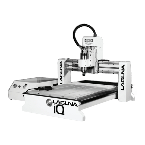
Page 10: Parts Of The Iq Machine
Router Spindle The router spindle is very high precision and water-cooled. The router spindle is moved in the three axes by precision ball screw system that are controlled by the machine controller. Frame The frame is a welded Router spindle Gantry Linear bearing rails heavy steel tubular... - Page 11 Electrical cable Water pump The water pump provides coolant for the router spindle motor. Running the router spindle without the cooling pump running can lead to spindle bearing failure. The pipe connector is push fit and is used for connection of the spindle water pipe.
- Page 12 Electrical control box with the lid removed Dust hood Dust hood (optional) The optional dust hood fits onto the router spindle and takes a 4-inch dust hose. It has a hinge side panel for easy access to the router spindle.
-
Page 13: Additional Instructions For The Use Of The Iq
Additional instructions for the use of the IQ Like all machines, there is danger associated with the machine. Injury is frequently caused by lack of knowledge or familiarity. Use this machine with respect. If normal safety precautions are overlooked or ignored, serious personal injury may occur. As the IQ is under the control of the onboard machine controller, it is important that you are clear of the cutter and moving parts when operating the machine. -
Page 14: Assembling Your Machine
Pipe fitting [may be loose not fitted] Touch off puck Cutters Allen key Water pump Hand held controller Collets Memory stick Tools Tool box Clamps Spare drive belt Assembling your Machine The IQ comes almost fully assembled with the exception of the water pump (optional), hand held controller, dust hood (optional), touch-off puck and connecting the electrical supply. -
Page 15: Electrical Connections For The Machine
Electrical cable Electrical Connections for the Machine The main power cable may not have a plug fitted, as it will be dependent on your installation. Ensure that when installing the electrical supply to the machine, 220v single phase is supplied. It is recommended that you use a 30-amp breaker. -
Page 16: Fitting The Optional Dust Hood
Fill a container about 3/4 full with clean water. If the pipe needs to be removed from the pump, press the outer ring into the fitting and gently pull the pipe out of the fitting. Note: You will need to provide a coolant tank with a minimum capacity of 5 gallons. If the shop temperature is high, the tank size will need to be larger. -
Page 17: Fitting The Router Bit Into The Router Head
Fitting the Router Bit into the Router Head Note: Before changing or fitting the router bit, always disconnect the power to the machine. Note: Collets and spindle collet holes must be cleaned regularly. Ensure that the slots in the collet are free of sawdust, as sawdust builds up and will stop the collet from compressing. If the collets or spindle holes are not clean, the router bit may not run true, and this will affect the performance of your machine. -
Page 18: Spindle Speed Control
3. Down Shear Router Bits These bits are similar to the up shear but with an opposite spiral that tends to pack the chips into the kerf. These bits prevent chipping the material surface, especially with veneers or melamine surfaces. 4. -
Page 19: Do's And Don'ts
DO’S AND DON’TS 1. DO verify water level in the spindle reservoir. 2. DO lubricate all ball screws every 8 hours of run. Use 30w oil or lithium white grease lubricant or equivalent to lubricate the ball screws. Wipe off any excess to reduce dirt and dust acumination. -
Page 20: Precautions Regarding Spoil Boards
Precautions Regarding Spoil Boards The spoil board is porous when the melamine has been cut through and will absorb moisture. As moisture is absorbed, the dimensions of the board will change. In general this will not be a problem, as the changes from day to day are not significant. Also the changes will, in general, be over the complete board. -
Page 21: Removing The Job From The Spoil Board
Removing the Job from the Spoil board If you use double-sided tape to attach the job to the spoil board, lever the job off the spoil board with a wide-blade putty knife or something similar. Fitting the Job to the Table Wide blade putty knife using the T-slots You may find it convenient to clamp the job to the spoil... - Page 22 Position of stop switches The stop switches are activated by proximity to steel items and can be tested by placing a screwdriver or something similar on the activation face (top). When activated, a LED should light. If the LED does not come on, the switch or wiring is faulty.
- Page 23 Noise Emission Termination strip VFD " Variable frequency drive" Fuse block Electrical control box Driver Power supply Interface board Electrical control box...
-
Page 24: Troubleshooting
Fuse Fuse holder open Fuses Note: Never access the inside if the electrical box with the mains is connected. The electrical functions of the machine are protected by fuses. To access the fuse, pull the fuse holder up. Once the fuse has been checked that it has not blown, ensure that the fuse holder is pushed down and is fully home. - Page 25 Machine vibrates 1. Machine not level on the bench. Re-level the machine, ensuring that it has no movement. Machine will not home 1. Are the home position sensors connected, damaged or out of adjustment? 2. Are the parameters in the hand held controller correct? 3.
- Page 26 For technical support contact, Laguna Tools at 1-800-332-4094 email Laguna Tools Customer Service at customerservices@lagunatools.com Please input machine type in subject line.
-
Page 27: Electrical Drawings
Electrical Drawings... -
Page 28: Exploded View Drawings And Parts List
Exploded View Drawings and Parts List... - Page 29 Hand-Held Controller Manual LAGUNA TOOLS 2072 Alton Parkway Irvine, California 92606 Part No. A11E Ph: 800.234.1976 www.lagunatools.com © 2016, Laguna Tools, Inc. LAGUNA® and the LAGUNA Logo® are the registered trademarks of Laguna Tools, Inc. All rights reserved.
- Page 30 Dear Woodworker: Thank you for your purchase and welcome to the Laguna Tools group of discriminating woodworkers. I understand that you have a choice of where to purchase your machines and appreciate the confidence you have in our products. Every machine sold by Laguna Tools has been carefully designed and well thought through from a woodworkers perspective.
- Page 31 Table of Contents Safety Rules...................... 4 Warranty......................5 Noise......................... 6 Specification General ..................6 Receiving Your Machine Shipping Damage and Inspection......6 Glossary of Terms..................... 7 Introduction......................8 Parts of the Hand-held controller..............9 Assembling the Hand-held Controller..............9 Controller Button Functions................10 To Move the Router Head................
-
Page 32: Safety Rules
Safety Rules As with all machinery there are certain hazards involved with the operation and use of your machine. Using it with caution will considerably lessen the possibility of personal injury. However, if normal safety precautions are overlooked or ignored, personal injury to the operator may result. -
Page 33: Warranty
We require the defective item/part to be returned to Laguna Tools, Inc. In the event the item/part is determined to have been damaged due to lack of maintenance, cleaning or misuse/abuse, the customer will be responsible for the cost of replacement of the item/part, plus all related shipping charges. -
Page 34: Noise
Noise Emission Notes concerning noise emission: Given that there exists a relationship between noise level and exposure times, it is not precise enough to determine the need for supplementary precautions. The factors affecting the true level of exposure to operators are clearly the amount of time exposed;... -
Page 35: Glossary Of Terms
Glossary of Terms Ball End Milling Cutter - A milling cutter that has a rounded cutting diameter at its end that is equal to the cutting diameter. DXF file - Drawing exchange Format file that was created as a standard to freely exchange 2 and 3 dimensional drawings between different CAD programs. -
Page 36: Introduction
MDI – Manual Data Entry, used for entering commands manually, line by line. CAD – Computer Aided Design, the using of computers to assist and develop design. CAM – Computer Aided Manufacturing, the use of computers to assist in manufacturing. CNC –... -
Page 37: Parts Of The Hand-Held Controller
Parts of the Hand-held Controller Key pad Display The hand held controller has the following parts. Key Pad This is used to input data into the HHC and to select the various functions. Display This communicates with the operator. Cable Interface Cable interface USB interface The main interface cable and USB... -
Page 38: Controller Button Functions
Controller Button Functions Note: Controller may vary form that shown. X+ / 1 = Moves the gantry in the X direction away from the home end of the bed. Y+ / 2 = Moves the gantry in the Y direction away from the home end of the bed. Z+ / 3 = Moves the router head in the Z [Up direction] away from the table surface. -
Page 39: To Move The Router Head
To Move the Router Head There are 3 different methods of moving the router head. 1. Continuous mode. Press the mode button until Continuous is displayed. The display will show [bottom row of the screen] the changing location of the router head as it moves location. -
Page 40: Resetting The Origin Point
2. Move the router head to the max X position by pressing X+ button until the router spindle stops and note the displayed AX= value. 3. Press the Y+ button and hold until the router gantry stops moving, note the displayed AY value. -
Page 41: Hhc Key Pad
4. Select the distance mode and enter 0.0254mm [0.0001”] Press Z+ [UP] and rotate the cutter in the reverse direction until the cutter is free to move and there is no drag. The cutter is now within 0.001” above the spoil board. 5. -
Page 42: Key Functions
Key Functions = Jog "Positive X" = Jog "Positive Y" = Scroll "Up" = Accelerate "Feed Rate" = Key "Number 1" = Key Number "2" = Jog "Positive Z" = Increase "Spindle = Set "Origin Point" Speed" = Key Number "4" = Key Number "3"... -
Page 43: Double Key Functions
Double Key Functions = Switch "Origin Points" 1-9 Note: When menu and a number are pressed this will take the router to the relevant origin point = Advance Work Menu = Move to Coordinates = Start program from a saved point = Activate C.A.D. - Page 44 = Run Last Array Work = Go to Coordinates = Set Park Position = Last Work Information = The Absolute Origin Point The Absolute Origin = Home Position Note: The Home position cannot ever be changed as it is controlled by the micro switches.
-
Page 45: Loading A Program Into The Machine
Loading a Program into the Machine The controller has a USB slot located to the top. 1. Load your program into your USB drive. 2. Fit the USB into the USB slot in the controller. 3. Press the button RUN PAUSE/ DELETE. The display will show U disc. 4. - Page 46 Laguna Tools is not responsible for errors or omissions. Specifications subject to change. Machines may be shown with optional accessories. © 2018, Laguna Tools, Inc. LAGUNA® and the LAGUNA Logo® are the registered trademarks of Laguna Tools, Inc. All rights reserved.
Need help?
Do you have a question about the IQ HHC and is the answer not in the manual?
Questions and answers