Table of Contents
Advertisement
Quick Links
Advertisement
Table of Contents

Related Manuals for HandTop HT3200-UV K Series


Summary of Contents for HandTop HT3200-UV K Series
- Page 1 3200 Hybrid UV printer installation instruction HT3200-UV_K...
-
Page 2: Table Of Contents
LIST FOREWORD........................Safety Precautions ....................... 1. Indications of symbols..............................3 2. Precautions of operations............................3 Introduction ........................1.Printer brief introduction..............................6 2.Printer Features................................6 3.Printer configurations..............................6 4.Structure Diagrams............................... 7 Printer installation....................1.Environment requirements............................19 2.Pre-installation................................20 3.Transportation and unload............................21 4. Installation..................................23 5.Software Installation.............................. -
Page 3: Foreword
FOREWORD UV printers are composed of precision mechanical and electrical parts. This manual is made for helping users to better use this product. The writing purpose of this manual is intended to allow the user to safe and efficient use of machines in a proper environment. Be sure to read the instructions carefully before using this machine. -
Page 4: Safety Precautions
Safety Precautions 1. Indications of symbols This symbol indicates the failures to be caused by the ignorance of misunderstanding of the instruction may probably lead to equipment damage or personal injury This symbol indicates the possible risk of the given operation This symbol indicates the improper operation to be strictly prohibited This symbol indicates the proper protections... - Page 5 Working environment Never use the printer in a non-ventilated or stuffy workplace, or it may lead to toxic hazards to operators. A ventilator is always a necessity. Do not use the machine in the explosive atmosphere. The printer is a precision equipment and should always avoid strong impact or shake in any process of loading, installation and operation, or it may result in equipment damage.
- Page 6 Operator awareness Any disassemble or replacement of the parts and cables is strictly prohibited in the state of power-on Avoid any body contact with the locomotion parts in the process of printer working, or it may lead to equipment breakdown or personal injury.
-
Page 7: Introduction
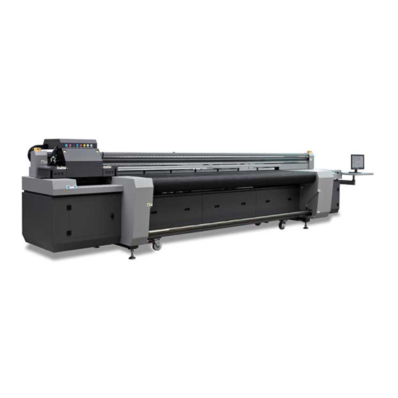
Introduction 1.Printer brief introduction The model of HT3200UV-D-K10 Kyocera Hybrid UV inkjet printer is highly cost-effective equipment specially designed for commercial printing enterprises. 2.Printer Features With the self-R&D ability that enables constant advancement. Professional assembly crafts guarantee the perfect qualities. Adopt high quality components (EGUS chain, linear motor) Ironic beam plus dual lead rails assembly on X-directional mechanical structure enables the carriage to run stably. -
Page 8: Structure Diagrams
Model HT3200UV_D Printhead Kyocera high-performance drop-on-demand piezo type heads Printhead 5-10PCS array Maximum 363*3600 DPI resolution Print size Up to 3.2m of printing width Media type Rigid and flexible printing media Printed 0-50mm thickness glass, acrylic, wooden board, ceramic tile, metals, PVC Applications board, corrugated board, plastic board, etc Ink type... - Page 9 1. Emergency Stop Button Front Left 6. Emergency Stop Button Front Right 2. Carriage 7. Printing Platform 3. Automatic Media Alignment 8. Media Take up Roller 4. Linear Motor Rail 9. Electric Control Panel Front 5. Beam 10. Computer Monitor Assembly 4.2 Rear view of the printer...
- Page 10 1. USB 2.0 Extension Port 6. Main Power Switch 2. Electric Box 7. Media Feeding Control 3. Media Guide Rollers 8. Media Feeding Roller 4. Electric Control Panel Rear 9. Suction Control Area 5. Ink Main Tank Box...
- Page 11 4.3 Electric Control Panel Front Right 1. Media Take-up Speed Control 4. Suction Power Control Switch Switch 5. Start Button 2. Suction Button 6. UV Mercury Lamp Control(Not For 3. Media Take-up Direction Control LED Lamp) Switch...
- Page 12 4.4 Electric Control Panel Rear Left 1. Suction Button 3. Media Guide Roller Button 2. Automatic Media Alignment 4. Print Button Button 5. Air Gun...
- Page 13 4.5 Carriage Component 1. Carriage height manual-adjust knob 5. White Purge Button 2. Color Purge Button 6. LED Lamp Assembly Right 3. LED Lamp Assembly Left 7. Anti-crash Assembly Right 4. Anti-crash Assembly Left 8. Air Gun 4.6 Suction area control...
- Page 14 1. Suction Area 1 3. Suction Area 3 2. Suction Area 2 4. Suction Area 4 4.7 ink system diagram 1. Ink Filter 2. Ink Main Tank 3. Ink Pump 4.8 Negative pressure system diagram...
- Page 15 1. Color Negative Pressure Pump 4. White Negative Pressure Pump 2. Solenoid Valve 5. Color Negative Pressure Tank 3. Negative Pressure Board 6. White Negative Pressure Tank 4.9 Electrical System Diagram...
- Page 17 1. DC24v Terminal Block 13. Negative Pressure Control Board For 2. Relay For Heating Suction 3. Relay For Blower 14. Blower Frequency Converter 4. Relay For Anti-static 15. X Linear Motor Driver 5. AC Contactor 16. Y Servo Driver 6. AC220V Terminal Block 17.
- Page 18 4.10 media loading diagram 1. Feeding roller 4. Driving roller 2. Driven roller 5. Take-up roller 3. Media guide rollers...
- Page 19 4.11 device label diagram Keep hands clear from running rollers Regular maintenance signs Caution for high temperature and ultraviolet light Pay attention to protecting eyes and hands Keep hands clear from running rollers Keep hands clear from the moving carriage Heavy object and two person lift required...
-
Page 20: Printer Installation
Printer installation 1.Environment requirements Field dimension at least 7.5*5m Without excessive dust and other pollutants Temperature: 18C ~ 30℃(64F ~ 86F) Humidity: 30%~70%RH Avoid direct sunlight Properly ventilated Max input power 8.3kW,max current 20A 3 phase AC power supply, 380V, grounding voltage is less than 3V The power cable specification must be no less than 4mm²... -
Page 21: Pre-Installation
Three phase 360-420V,50~60Hz 2.Pre-installation 1. Prepare the working field under previous instruction. 2. Install distribution box under previous instruction, prepare a 15KVA voltage regulator. 3. Prepare 2 pcs of monkey wrench, 1 pcs of spirit level, 6L of coolant(pure water or anti-freeze fluid) for the LED lamp chiller. -
Page 22: Transportation And Unload
≥500G Windows7 64bit (Industrial pc) supported Handtop control software is not available in Windows8 and Windows10 system for the time being 3.Transportation and unload 3.1Site transport Another forklift would be needed if unload from a container or hoist onto building. - Page 23 If lifting to upper floors needed, please mount the hoisting rope to the foot cups according to image 1 and 2, then proceed hoisting operation. Net weight: 2350kg Equipment size: 5530mm*1320mm*1325mm This printer is belong to heavy, high precision and expensive machine, it is highly recommended to hire professional carriers to perform loading and transport operations to avoid accidents.
-
Page 24: Installation
3.2 Devanning process 1. First remove the screws on the top of box and the upper plate. then remove five red mounted bars. In order to avoid the damage from the bar against the machine, do remember hold the bar before unscrew the screws. 2. - Page 25 3. Remove the carriage locking parts on the right side of the beam, see the picture below 4.2 Equipment level adjustment Tools: Level(Precision range 0.02mm/m), monkey wrench When adjusting the level on the right/left side, the level should face the same direction.
- Page 26 3. Place the level between position A and C, or between position B and D, check for the height for A,B,C,D points, then adjust the foot cup height according to the reference from step 2. 4. Adjust the 4 points to the same level with the assist of level, lock the foot cup screw to prevent loose 5.
- Page 27 Install the display and PC according to the above picture and put the USB cable, PC start cable, display signal cable and power cable into the crate. 4.3.2 Install PCIE cards (Pictures below are for the 2X5 configuration, for 2x4 configuration only one PCIE card) Install the PCIE card to the PC.
- Page 28 Kyocera 2x4 V1.1 PCIE card Kyocera 2x5 V1.2 PCIE card 4.3.3 Connect the cables on PC (Pictures below are for the 2X5 configuration, for 2x4 configuration only one PCIE card) 1. Display VGA Cable 7. Optical Fiber Cable No.2 (Connect to 2.
- Page 29 4.4 LED module installation 4.4.1 LED lamp installation Install the LED lamp to the fixing plate at two side and connect the power cable, shutter control cable and anti-collision signal cable. The anti-collision module must be lower than jet plate with 0.5mm. Put an acrylic on the platform and start the height detection function with 2mm setting.
- Page 30 Connect the cooling circulation tube to the water hose. Then open the water-IN valve. Connect the power unit to 220V power and start the chiller working. Finally add the pure water(temp above 10℃) or anti-freezing water (temp under 10℃)
- Page 31 4.4.3 Setting of chiller OPERATION INSTRUCTION MANUAL The contents of the three digital displays are as follows: D1 displays the real-time water temperature and displays the setting items when the status. D2 displays the set value, displays the setting item value when setting the status, and displays the error code during the alarm.
- Page 32 Button function introduction: AUTO: (Smart mode) Entry method: Press once to enter the mode, press AUTO (D1) again to display the room temperature, and automatically return to the display water temperature after 3 seconds. CONSTANT (constant temperature mode) Entry method: same as smart mode entry method and function SET (Settings): Entry method: Press SET key...
- Page 33 AUTO: (Smart mode) (factory default: -2℃) The D2 displays the difference value between the water temperature and the room temperature. Press the up and down keys to change the set value and set the temperature deviation range (-5℃--+5℃), water temperature (D1) range = room temperature + (D2) ±...
- Page 34 C3: Water shortage alarm delay time (1S –100S): Continue to work normally when the water shortage time is detected is less than this value. C4: Lower limit temperature setting (1℃-25℃). If it is lower than this value, it will not be cooled; this value cannot be higher than the set temperature value of the constant temperature mode.
- Page 35 C6: Heating rod start temperature (1℃-20℃): C6 is 2 degrees lower than C4, otherwise it cannot be adjusted. C7: Maximum room temperature alarm function (42℃-50℃): When the room temperature exceeds this C7, the alarm signal is output and the Cold water machine compressor stops working.
- Page 36 The meaning of the fault code is as follows: 2 PCB communication anomalies. Generally due to the connection lines of the boards are damaged or loose. E1: Too high water temperature protection. Water temperature exceeds (target value + C0), too high protection fault output interrupt signal. E2: Too low water temperature protection.
- Page 37 It is normal if it changes toward the target value and changes more than 0.3 degrees every 30 seconds. If the change of continual 3 times *30 seconds does not meet the requirements, then the alarm program detects if the temperature difference reaches the alarm value and then starts the alarm.
-
Page 38: Software Installation
the connection is correct and normal, switch on from ip to down. Main power locker should open to the up before turn on the main power and connect to the electricity. Finally start the PC and machine. 5.Software Installation 5.1Topjet Installation Select the driver version accordingly Double click the driver, choose language Select X64, only available for WIN 7 64bit OS... - Page 39 Select the communication port Select the printer model...
- Page 40 Select lamp type Browse a path for TopJet.
- Page 41 It’s recommended to not choose system disk as installation folder. For example, “E:\”. Thus, the package will generate a folder named “E:\TopJet” automatically. Select additional task Install...
- Page 42 Install Click finish to continue...
- Page 43 Install the driver for PCIE card...
- Page 44 Accept and click next Continue...
- Page 45 Finish. Normally we do not have to reboot computer after installation. 5.2 Topjet software operation guide...
- Page 46 5.2.1 Main interface Function interface Introduction Controlling the carriage right/left motion, Y direction front/rare motion Stop button Up and down carriage motion, zero adjust for height sensor Equipment diagnose, the machine will automatically run the diagnose by a click List for awaiting printing files Finished printing files Print button, it will be in grey color if no printing file selected Margin and header settings...
- Page 47 Calibration printing list Circular printing mode including auto and manual options, do not select it while copy printing is selected. Copy printing function, can’t be selected together with circular printing at the same time. 5.2.2 Test and calibration interface Function interface Introduction 1.
- Page 48 Print head spray function. The print head will frequently spray inks after click. The version info for the software. Other functions are the same as the main page. 1. Print head status test: Print test strip and observe print head status 2.
- Page 49 adjust the stepping 1. This model does not support “Continuous stepping to adjust the belt” 2. During the printing, the carriage will automatically adjust if the carriage height changes. The bi-direction offset will automatically adjust its self if the carriage height changes for adapting the media thickness in the printing process.
- Page 51 1. Base pointer can be adjusted by changing the value of header and margin. 2. Header: Please adjust it according to the production need. 1. Fill: Filling white ink in the blank area within the image size. 2. Base: Print a full format layer of white before CMYK printing.
- Page 52 1. Optional printing modes: Draft, Production, quality, high density. The default printing settings are available for adjustment. 2. Direction options: uni-direction and bi-direction 3. Optional screen value: 1.0, 0.75, 0.5, 0.33, 0.25. 4. Ink Density: Each 1x of density will increase 1x of pass number.
- Page 53 Function interface Introduction 1. Spray setting: An intermittent jetting motion when the print heads are under nonworking state. This function is to prevent the ink block the nozzle under long time of settling. Press the set button to confirm after the settings been altered.
- Page 54 1. Motion control option: Settings for printer motion control. 2. Stepping speed and curing compensation: This function is to compensate the curing pass and stepping speed after the printing finished. Stepping speed options include 1.0x and 1.3x, curing compensation include 2/4/6pass.
- Page 55 1. Ink supply system status: The green light means normal status; yellow light means abnormal status. For different colors, the status information will be shown. 2. Reset button: Reset function for external device control board, equal as reboot the external device control board.
- Page 56 is turned off. The grey area between i1 and i2 is the radiation area of the curing lamp on the left of the car. If the irradiation area is found not to coincide with the image, two parameters, "left light on position adjustment (mm) when the car moves to the right"...
- Page 57 movement to the right. Left light on position adjustment (mm) of left light when car moves left and left light off position adjustment of left light when car moves left (mm) : According to the figure below, the upper left arrow indicates that the car is moving to the left, and the black solid rectangle on the left side of the car indicates the left curing light .The vertical line i2 represents the position where the UV curing lamp is turned on, while the vertical line i1 represents the position where the UV curing lamp...
- Page 58 The position adjustment of the right light on when the car moves to the right (mm) and the position adjustment of the right light off when the car moves to the right (mm) : According to the figure below, the large right arrow above indicates that the car is moving to the right, and the solid black rectangle on the right of the car indicates the right curing lamp.
- Page 59 5.2.6 Heads parameter Setting...
- Page 60 5.3 Kyocera waveform writing After finishing the installation of heads, enter “head parameter setting” First select “stand” waveform, click “write”, wait for 1min, then click “read” to check if the waveform is written successfully. (If not, please do it again.) Then select the waveform you want(e.g.
-
Page 61: Printhead Installation And Calibration
6.Printhead installation and calibration 6.1 Print head installation process This operation should be performed by professionally trained personnel to avoid accidental injury or device damage. The ribbon cable must be connected in the event of a power outage, and the pin of the ribbon cable must not be stained with ink or flush. - Page 62 Assembling head inlet and outlet ink tube. Check the filter and the inlet tube, make sure the lower tube is thicker than upper tube, then connect the big connector. Also connect the outlet tube with the small connectors.
- Page 63 Finish assembly of tube, as shown in picture below. (Left is the outlet tube, right is the inlet tube)
- Page 64 Clean all tubes with flush Connect the tubes with the heads As shown in pictures below...
- Page 65 Remove the screws on the plate. (one is at the back side, one is at the front side) Remove the protective film...
- Page 66 Put the head to the right position Discharge the protective fluid of the head...
- Page 67 Connect the head cables, grey is data cable, the white is power cable. After finish all assembly, as shown in picture below...
- Page 68 6.2 Filling ink After installed the printheads, check the ink circuit and connection again, and then make sure that the filling ink operation is not carried out until it is correct. Turn off the spray function in the software and lower the negative pressure to-1.2 kpa.so that the negative pressure after filling ink is larger than the protection.
- Page 69 Loosen the cap of the air exhaust tube of the printhead, and press the ink prime button till you see a constant ink stream comes out of the tube. Then seal the tube with the cap. Execute the exhaust on each printhead as the operations described above.
- Page 70 According to the testing picture, adjust the vertical alignment screw and repeat step 3. Repeat step2/3/4 till the calibration of heads vertical is ok. How to observe the testing picture of heads vertical? Testing picture of Testing picture of heads heads vertical (Overlapped) vertical (not overlapped) Exclamation point position, two groups of...
- Page 71 Choose “Nozzle alignment ” in the drop-down menu and print. Observe the calibration print through a magnifying glass and see if the left and right parts overlap. Adjust the horizontal alignment fixing screw according to the calibration printing coincidence. Repeat step 1 / 2 / 3 till nozzle alignment is ok, see the picture below.
- Page 72 6.5.3 Left/right direction offset Left/right direction offset indicates the calibration parameters of the nozzle jetting from left to right and from right to left. Select “Left direction offset” in the drop-down menu and print. Observe the calibration print through a magnifying glass Write down the corresponding parameters that have been aligned.
- Page 73 Select “Bidirectional offset” in the drop-down menu and print. Observe the calibration print through a magnifying glass and write down the aligned parameters. Repeat step 1 / 2 / 3 at corresponding speed for modifying bidirectional offset till Bidirectional offset is ok. Different vehicle velocities correspond to different bidirectional calibration parameters, please calibrate separately.
- Page 74 How to observe the testing picture of stepping calibration? Stepping calibration(Overlapped) Step calibration method is an imprecise algorithm, select the nearest numerical modification. 6.5.6Calibration of printing base pointer Select “Printing base pointer” in the drop-down menu and print. Measure and calculate the difference between the actual value and the expected value.
- Page 75 Modify the page header base point based on the margin.
-
Page 76: White Printing Mode
6.6 Calibration confirmation This test picture checks the status after calibration. 7.White printing Mode 7.1 Not print Only color layer is printed. 7.2 Overcoat Within the image frame, above the color layer, print solid density white. - Page 77 7.3Middle layer Within the image frame, in between the top and bottom color layers, print solid density white. 7.4 Base Within the image frame, under the color layer, print solid density white.
- Page 78 7.5 Fill Within the image frame, in the empty(no color data) area, print solid density white. 7.6 Middle layer of image In the area where there is color data, in between the top and bottom color layers, print variable density white based on the color data.
- Page 79 7.7Overcoat of image In the area where there is color data, above the color layer, print variable density white based on the color data. 7.8 Base of image In the area where there is color data, under the color layers, print variable density white based on the color data.
- Page 80 7.10 Spot In the area defined as spot, print white based on the spot channel density data. 7.11Middle layer of spot In the area defined as spot, in between the top and bottom color layers, print white based on the spot channel density data.
- Page 81 7.12Overcoat of spot In the area defined as spot, above the color layer, print white based on the spot channel density data. 7.13Base of spot In the area defined as spot, under the color layer, print white based on the spot channel density data.
-
Page 82: Operation Instruction
Operation instruction 1.Machine turn-on Pay attention to the safty instruction in chapter 6; First operation must under professional techinical engineers’ guidence. Use E-stop when meeting urgent issue, to protect the machine. Connect the main power cable Turn on the main air switch Start the PC Turn off the E-stop and turn on the start button for machine self checking. -
Page 83: Machine Turn-Off
2.Machine turn-off Testing strip printing Fan and LED lamp OFF Check the negative pressure and sprary function PC OFF Machine cleaning... -
Page 84: Maintenance Instruction
Maintenance instruction 1. Periodic maintenance To ensure the good condition of the equipment, users need to follow below instructions for regular cleaning and maintenance of the equipment. Clean the machine body Empty the waste ink Daily Clean printhead mounting plate maintenance Check the negative pressure system Check the nozzle test (print head status) -
Page 85: Motion Component Maintenance
Add lubricating grease to motion parts Monthly Check ink tube and air tube connections maintenance Replace the air pump Seasonal Replace the ink pump filter maintenance Replace ink pump and fiber cable Replace the printhead filter Annual maintenance Replace the ink tube in the chain 2. -
Page 86: Precision Components Maintenance
3. Precision components maintenance Must use absolute alcohol and clean cloth for the cleansing of the precision components. Raster strip Photoelectric switch Precision components Carriage height sensor components 4. Printhead maintenance 4.1 Daily maintenance of printhead Print the nozzle test every on and off duty, check for nozzle status see if any blockage If there are nozzles blocking, dispose immediately. -
Page 87: Commonly Used Parts Replacement Instructions
5. Commonly used parts replacement instructions 5.1 Replace the ink pump When the machine is alarming 3 beeps, check the ink pumps This is not the only possibility, see the alarm system Unplug the ink pump power housing and loose the fixing screw; Replace with new ink pump;... - Page 88 Connect the ink pipe to the new pump. Pay attention to the flow direction, fix the screw, and connect the power housing. It is normal to hear 3 beeps during the procedure. Click "Reset" in the software to finish. 5.2 Add ink If you hear 6 beeps, check the main tank see if it is running out of ink.
- Page 89 The ink pump filter should be changed every 3 months Remove the ink pump power housing; Block the ink pipe to avoid backflow; Remove the ink pipe and the filter; Replace the filter and pay attention to the direction; Stop blocking the ink tube and complete the replacement. 5.5 Replace air tube Replace the air tube immediately if any damage is found...
- Page 90 Close the spray function and close the ink valve Press the emergency stop switch, disconnect the pump power housing; Open the chain; Replace the new air tube; Mark the airflow direction to avoid the mistake; Install and fix the air tube; Install the chain and switch on the printer;...
-
Page 91: Maintenance Instruction
Maintenance instruction 1. Alarm system There are six kinds of alarms in the equipment, below are the troubleshooting methods for various alarms One beep,【Bi】 Alarm type Problem Air Pump failure The main air pump stops and the backup pump is Reason working First click "reset"... - Page 92 Check if the main tank is starving, if so, add ink. Check the liquid sensor in sub-tank. Diagnose Check the ink pump see if it’s running normally. Check the ink pump for blockage. Check the ink supply system for leakage. Check the ink pump filter for blockage Alarm type Four beeps,【Bi-Bi-Bi-Bi】...
- Page 93 Do not break the ink tube when replacing it. The leakage will cause backflow. Activate the printer and open the ink valve on the Diagnose backflow ink box Drain the ink until the liquid level returns to normal height Alarm type Six beeps【Bi-Bi-Bi-Bi-Bi-Bi】...
-
Page 94: Negative Pressure System
2. Negative pressure system 2.1 Purge failure Description Continuous press the purge button, but the ink is not coming out from the nozzles Check the status of the corresponded solenoid valve Diagnose Check if the sub-tank is empty (3 beeps) Check the positive pressure see if it’s normal 3. - Page 95 For rough surface and heat sensitive material, please adjust the vacuum power and area before printing, this is to get more stable suction. Since the height sensor is not in the base point, it may never touch the substrate if the medium is in very small size. To avoid this from happening under this circumstance, it is recommended to place the media under the sensor to perform height detect then register the media to the printing area.
- Page 96 3.2 Print head scratch and crash accident treatment Wait for the error message to show on the interface and click ok Rise the carriage height as below image showing, remove the media. Reposition the baffle of the anti-crash on the carriage, as below image Click the back to origin button to restore the carriage to the base point.
- Page 97 It is recommended to print the nozzle test immediately after troubleshooting if there is an accident of rubbing the nozzle surface against the media. Check whether the nozzle is damaged and repair it immediately.
-
Page 98: Carriage Motion Anomaly
4.Carriage motion anomaly 4.1 Error code for FUJI motor driver When the carriage motion is malfunction, the screen on the driver will show error code. Please diagnose according to the error code. Code Meaning Treatment mber oc1 or oc2 Over current Check and repair power line (U, V, W) wiring oL1 or oL2... - Page 99 ¯PoF Anti-collisi Check the anti-collision device and return to normal emergenc y stop ¯Pn0 Registration Check and restore the media device is on registration device to normal state =Pot Y axis If Y displays this code when it base point is not at the origin, check whether display the photoelectric switch is...
- Page 100 Description The software alert for error, interface shows below warning: “Device is busy, please check the media location plate, raster reader and motor driver, try again.” Diagnose 1. The anti-collision device is triggered. 2. The raster encoder crash with obstacles and changed position, causing data reading failure.
- Page 101 4.4Height detect anomaly Description When performing height detection, the carriage can lift up but can’t go down. Diagnose The height detect components are dirty cause high friction and the probe cannot go down. Please clean the components. The height detect switch break down. Replace the height detect switch.
-
Page 102: Tools And Attribute
Check the print head height see if it is too high, normally should be 2mm from the nozzle to Fuzzy printing quality substrate surface. Clean the print head surface, redo calibration Adjust colors in the job editor, if the color is darker, Printing color darker or lighter. - Page 103 Tool Function Diagonal pliers Cut off the ink tube and air tube Ink valve spanner Open and close the ink valve Monkey wrench Adjust the level of the machine Allen Key Adjust the inner hexagon screw Phillips screwdriver Adjust the cross and slotted screws Slotted screwdriver Cleaner...
-
Page 104: Instruction For Ht3200 Conveyor Belt Rectify
Instruction for HT3200 conveyor belt rectify I. Rectifying use guide: 1. This instruction only refer to HT3200B/C/B3200 models; 2. Please read this instruction carefully before power on the machine. II. Tool Allen Key III. Operation guide No matter large format belt or conveyor belt, it will run stable if both edges share the same tightness. - Page 105 age 1 When the belt on the rectify roller movable side is loose, it will move left to press the belt on this side to balance the tension of both sides of the conveyor belt. In contrary situation, the rectify roller will move right to leave the belt on this side, the tension of both sides will be balanced.
-
Page 106: Operation
Image 2 2.Operation The conveyor belt rectifying device is with simple and tight design, during the machine operation, it is user-friendly for customers. After the conveyor belt assembled, the belt tightness can be adjusted by the adjusting screw on both sides of the rectify roller (... - Page 107 During the machine operation, there are 2 focusing type photoelectric switches giving out red modulating light pointing the conveyor belt edge. Through the control program, the motors controlling the ball screw will run in different direction according to the signal and move the rectify roller to the left and right. (See image 5 and 6) Conveyor belt edge...
- Page 108 Left Right Rectify roller Swing mounting plate Ball screw nut L/R Micro-switches Image 7 When the rectify roller is moving right or left, the swing mounting plate in the bottom will trigger one of the micro-switches, the servo motor will stop working, the rectify roller will stay in right or left and stabilize the belt movement continuously.
- Page 109 IV Technical requirements 1. Test run the machine each time start up the machine, observe carefully for anomaly shaking and noise. After confirmation, begin working. 2. Observe for the photoelectric switches and micro-switches, they should be giving the right signal.
-
Page 110: Cable Diagram Of Ht3200D Head Configuration(2X5)
Cable diagram of HT3200D head configuration(2X5) Mode:DA_YMCKKCMYWW Mode:DA_YMCKKCMY_... - Page 111 Mode:DA_CMYKW Mode:DA_+_CMYKW...
- Page 112 Mode:DA_YMCKKCMYWW Mode:DS_CMYK...
Need help?
Do you have a question about the HT3200-UV K Series and is the answer not in the manual?
Questions and answers