Table of Contents
Advertisement
Quick Links
(847) 360-9170
World Leader in Used Die Casting Machinery!
RECENT
INDUSTRY
JOIN OUR
SELL US
HOME
ADDITIONS
SERVICES
MAILING LIST
YOUR MACHINE
If we can be of any assistant or if you have any questions,
please don't hesitate to contact us at (847) 360-9170.
You may also visit our website at
https://www.diecastmachinery.com
Thank you!
Advertisement
Table of Contents

Related Manuals for Sterlco 6017 Series


Summary of Contents for Sterlco 6017 Series
- Page 1 (847) 360-9170 World Leader in Used Die Casting Machinery! RECENT INDUSTRY JOIN OUR SELL US HOME ADDITIONS SERVICES MAILING LIST YOUR MACHINE If we can be of any assistant or if you have any questions, please don't hesitate to contact us at (847) 360-9170. You may also visit our website at https://www.diecastmachinery.com Thank you!
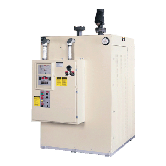
- Page 2 $30. Operation and Installation Manual 6017 Series Large Hot Oil Temperature Control Units Important! Read Carefully Before Attempting to Install or Operate Equipment Part No. 682.91540.00 Revision 2 Bulletin No. SC1-655...
- Page 3 ________________ ________________ ________________ ________________ ________________ Sterling/Sterlco is committed to a continuing program of product improvement. Specifications, appearance, and dimensions described in this manual are subject to change without notice. © Copyright Sterling/Sterlco and Sterling, Inc. 2003 All rights reserved. Effective 10/17/2003 Part No.
- Page 4 Safety Considerations Sterling/Sterlco 6017 Series large hot oil temperature control units are designed to provide safe and reliable operation when installed and operated within design specifications, following national and local safety codes. To avoid possible personnel injury or equipment damage when...
-
Page 5: Table Of Contents
If the Shipment is Not Complete............ 18 If the Shipment is Not Correct ............18 Returns ..................18 Installation............... 19 Work Rules ................... 19 Installation Requirements.............. 19 Connecting Piping ................. 20 Making Electrical Connections ............26 Page 4 6017 Series Hot Oil Large Temperature Control Units... - Page 6 Identifying System Status Board Indicators........41 Preventive Maintenance......... 46 Periodic Checks ................46 Routine Servicing ................47 Draining the Unit for Storage............50 Corrective Maintenance ..............50 Maintaining the Pump ..........See Addendum Troubleshooting ............. 52 6017 Series Hot Oil Large Temperature Control Units Page 5...
- Page 7 Charts and Figures 6017 Series Hot Oil Large Temperature Control Unit and Specifications 6017 Unit Piping Setup Typical Flow Schematic Typical M2B Graphic and Button Control Panel Control Panel Switches System Status Board Indicators Page 6 6017 Series Hot Oil Large Temperature Control Units...
-
Page 8: General Information
General Information Introduction Your Sterling/Sterlco 6017 Series hot oil temperature control unit circulates thermal transfer-type oil through your process and to precisely, automatically, and reliably maintain it at a temperature you can select. The operating range of your temperature control unit is from 100°F to 550°F (38°C to 288°C). -
Page 9: Models Covered
Models Covered This manual lists installation, operation, and maintenance instructions for the 6017 Series hot oil large temperature control unit. Model numbers are listed on the serial tag. A model number followed by indicates a specially constructed unit, and not all information in this manual may apply. -
Page 10: Available Options
All models are built to provide full or partial heat as required by the process and determined by the controller, to provide more precise control. 6017 Series Hot Oil Large Temperature Control Units Page 9... - Page 11 Each Fulflo is factory preset to limit system pressure as specified by the customer. It must not be tampered with in any way. Page 10 6017 Series Hot Oil Large Temperature Control Units...
- Page 12 Cooling Optional The Sterlco-designed shell and tube heat exchanger is provided as optional equipment in this unit. The design features U-tube construction and copper-nickel tubes for durability and optimal heat transfer.
- Page 13 • low fluid pressure • low fluid level (optional) • high fluid level (optional) Push the button to silence the alarm. See ALARM SILENCE Chapter 4 for more information on control functions. Page 12 6017 Series Hot Oil Large Temperature Control Units...
- Page 14 Failure to purge the system of air before heating may result in serious injury or critical system and equipment damage. Make sure you properly purge the system of air before starting the heater cycle. 6017 Series Hot Oil Large Temperature Control Units Page 13...
- Page 15 • 40 gallons (151 liters) on 6017L & 6017M units • 65 gallons (246 liters) on 6017P & 6017V units. The tank permits thermal expansion of the heat transfer fluid, and provides make-up fluid. Page 14 6017 Series Hot Oil Large Temperature Control Units...
- Page 16 WARNING The reservoir tank may cause serious injury if it ruptures from not being properly vented. Make sure that the reservoir tank is always properly vented to prevent tank rupture. 6017 Series Hot Oil Large Temperature Control Units Page 15...
-
Page 17: 6017 Unit Piping Setup
3,200 1,452 ♠ The actual shipping weights may vary based on options selected. The shipping weights listed are the maximum shipping weights for standard units of the listed cabinet size. Page 16 6017 Series Hot Oil Large Temperature Control Units... -
Page 18: Shipping Information
Shipping Information Unpacking and Inspection You should inspect your Sterling/Sterlco 6017 Series hot oil large temperature control unit for possible shipping damage. If the container and packing materials are in re-usable condition, save them for reshipment if necessary. Thoroughly check the equipment for any damage that might have occurred in transit, such as broken or loose wiring and components, loose hardware and mounting screws, etc. -
Page 19: If The Shipment Is Not Complete
If the Shipment is Not Complete Check the packing list. The apparent shortage may be intentional. Back-ordered items are noted on the packing list. You should have: 6017 Series hot oil large temperature control unit Bill of lading Packing list... -
Page 20: Installation
Take care when selecting a location. The area surrounding the unit must be free of obstructions to ensure proper ventilation of internal components. Allow a minimum clearance of at least 30 inches (76 cm). 6017 Series Hot Oil Large Temperature Control Units Page 19... -
Page 21: Connecting Piping
Do not install process or water supply/drain piping smaller than the fittings on the unit. If the water supply piping is larger than unit fittings, reduce the pipe size at the unit. Page 20 6017 Series Hot Oil Large Temperature Control Units... - Page 22 You can purchase high-quality flexible metal hose from Sterling/Sterlco to allow for thermal expansion of the process piping; state the length you want when ordering. 6017 Series Hot Oil Large Temperature Control Units Page 21...
- Page 23 55-gallon (208-liter) drum. This practice ensures that overflow will not create a hazard to personnel. Remember: All external piping must be supported independently of the 6017 unit. Page 22 6017 Series Hot Oil Large Temperature Control Units...
- Page 24 Make sure lines and connectors have a service rating of at least 100 psig (689.5 kPa/6.9 bars), and a temperature rating at least equal to the maximum operating temperature of your 6017 unit. 6017 Series Hot Oil Large Temperature Control Units Page 23...
-
Page 25: Typical Flow Schematic
• Return Valve - closed for purge/ open for run/ closed for pump reverse. • Reservoir Tank - Open to atmosphere at all times, unless nitrogen blanket provisions are present. Page 24 6017 Series Hot Oil Large Temperature Control Units... - Page 26 4.) Once all of the air has been replaced with fluid, and only oil is being dumped into the reservoir; close the vent valve. 5.) Open the isolation valve that is returning the oil from the process. 6017 Series Hot Oil Large Temperature Control Units Page 25...
-
Page 27: Making Electrical Connections
Operators should not have to squeeze around the 6017 unit to reach disconnects, especially in case of emergency. • When running conduit whips to the 6017 unit, make sure that whips are routed away from hot piping. Page 26 6017 Series Hot Oil Large Temperature Control Units... - Page 28 Run electrical connections to the supply terminals from either side of the unit. Make sure that all three phases are wired correctly. The pump runs backwards if not wired properly. 6017 Series Hot Oil Large Temperature Control Units Page 27...
- Page 29 - Notes - Page 28 6017 Series Hot Oil Large Temperature Control Units...
-
Page 30: Startup Preparations
100°F (38°C) and switch unit into the "Auto" mode. As the oil warms up, viscosity will decrease, and the pressure will fall. 9. In 2-minute intervals increase the setpoint to 150°F (66°C) and 200°F (93°C). 6017 Series Hot Oil Large Temperature Control Units Page 29... - Page 31 5. As fluid is drawn out of the reservoir tank to fill the process, the fluid level will fall in the tank. Continue to add fluid to maintain the level about 4 inches from the bottom of the sight glass. Page 30 6017 Series Hot Oil Large Temperature Control Units...
- Page 32 NOTE: If all traces of water are not removed from the system, severe cavitation may occur at elevated temperatures. Indications are a “gravely” sounding pump, fluctuating or dropping pressure, or rapidly rising fluid level in the expansion tank. Repeat Steps #9-12 if this occurs. 6017 Series Hot Oil Large Temperature Control Units Page 31...
-
Page 33: Shutting Down The Unit
The total capacity of the tank can be found on page 14. If it appears that the tank may overfill, connect a line from the port of the reservoir tank to FILL a clean auxiliary container. Page 32 6017 Series Hot Oil Large Temperature Control Units... - Page 34 - Notes - 6017 Series Hot Oil Large Temperature Control Units Page 33...
-
Page 35: Using Controls And Indicators
LO HEAT COOL FLOW FLUID SAFETY HI/LO PROBE MOTOR PRESSURE THERMO ALARM FAIL FAIL DOWN ENTER SET POINT INDEX DISPLAY ALARM ALARM STERLING, INC. TEMPERATURE CONTROL SYSTEM -- M2B MILWAUKEE, WI Page 34 6017 Series Hot Oil Large Temperature Control Units... -
Page 36: Identifying M2B Controller Panel Components
COOL point and is being cooled. Display Indicators TO PROCESS Indicator indicator is on when the TO PROCESS PROCESS screen on the controller displays the temperature of the outgoing fluid. 6017 Series Hot Oil Large Temperature Control Units Page 35... - Page 37 PROBE FAIL probe fails. A delivery probe failure displays on the screen, and a return probe failure displays on the screen. The alarm resets after the failed probe is replaced. Page 36 6017 Series Hot Oil Large Temperature Control Units...
-
Page 38: Using M2B Controller Keys
LED screens. Important! Do not change any of the control settings without consulting the Sterling/Sterlco Service Department. The Sterling, Inc. warranty does not cover TCU failures from tampering with controller settings! 6017 Series Hot Oil Large Temperature Control Units Page 37... - Page 39 INDEX Key INDEX Each press of the key advances the screen to the INDEX next menu item. Refer to your Sterling/Sterlco M2B Temperature Control Owner’s Manual for a list of functions available using this key. ALARM HI ALARM Key ALARM...
-
Page 40: Identifying Control Panel Switches
These switches control the operation of the unit. Figure 5 Control Panel Switches PUMP ALARM START SILENCE PUMP START ALARM SILENCE STOP AUDIBLE ALARM PUMP STOP REVERSE PUMP REVERSE MODE MODE SELECT AUTO MAN. COOL 6017 Series Hot Oil Large Temperature Control Units Page 39... - Page 41 Never switch to AUTO mode when filling or venting the unit, except as described in the Unit Startup chapter. Improper switching can seriously damage the heater, as it could become energized with air in the system. Page 40 6017 Series Hot Oil Large Temperature Control Units...
-
Page 42: Identifying System Status Board Indicators
POWER ON PUMP REVERSE AUTO PUMP FORWARD BYPASS RELIEF VALVE HEATER DELIVERY PRESSURE SAFETY THERMO HEAT STRAINER EXCHANGER VENT HIGH RETURN COOL LEVEL SOLENOID FILL VENT DRAIN LEVEL SOLENOID RES. TANK 6017 Series Hot Oil Large Temperature Control Units Page 41... - Page 43 Select the unit operating mode by using the selection switch. Power On Mode Indicator Light mode indicator light illuminates to indicate that the Power On control circuit is energized in the unit. Page 42 6017 Series Hot Oil Large Temperature Control Units...
- Page 44 This is an alarm condition, so the audible alarm activates to notify you of the safety thermo fault, and disables controller outputs, permitting the pump to continue to circulate fluid to avoid damage. 6017 Series Hot Oil Large Temperature Control Units Page 43...
- Page 45 This is an alarm condition, so the audible alarm activates to notify you of the low fluid level fault, and the controller outputs are disabled. Always correct the alarm condition before returning to normal operation! Page 44 6017 Series Hot Oil Large Temperature Control Units...
- Page 46 - Notes - 6017 Series Hot Oil Large Temperature Control Units Page 45...
-
Page 47: Preventive Maintenance
• Check for leaks developing at the pump seal, gaskets, and other similar locations. • Check the pump drive V belt for any wear. • Check the reservoir tank vent for any obstructions. Page 46 6017 Series Hot Oil Large Temperature Control Units... -
Page 48: Routine Servicing
This is especially true for the pump. It relies on free air circulation for proper cooling. Check the motor air intake screen for any accumulation of dirt; clean it as needed. 6017 Series Hot Oil Large Temperature Control Units Page 47... - Page 49 • Inspect the screen in the Y strainer for accumulations of debris. Clean as needed. Servicing the Unit Every Three Months Remove and clean the screen in the Y-strainer. Replace the screen if it is damaged. Page 48 6017 Series Hot Oil Large Temperature Control Units...
- Page 50 1/3 full of grease and outboard bearing cavity should be about 1/2 full of grease.) Note: Bearing is 1/3 full when only one side of bearing is completely full of grease. 3. Assemble motor. 6017 Series Hot Oil Large Temperature Control Units Page 49...
-
Page 51: Draining The Unit For Storage
Note: If the pump motor wiring is disconnected for removal from the unit, you must check the actual direction of rotation when the motor is rewired to the unit. Page 50 6017 Series Hot Oil Large Temperature Control Units... - Page 52 6017 Series Hot Oil Large Temperature Control Units Page 51...
-
Page 53: Troubleshooting
Check heater tank for scorched/ discolored paint. Check Heater burnout. resistance on all three (3) legs of heater with an ohmmeter. Replace heater as needed. Page 52 6017 Series Hot Oil Large Temperature Control Units... - Page 54 Replace as required. Drain water from low point in Water in fluid. piping (see Chapter 3), or boil Noisy pump. water off. Drain and flush system. Replace Severely degraded fluid. fluid. 6017 Series Hot Oil Large Temperature Control Units Page 53...
- Page 55 Service Notes Page 54 6017 Series Hot Oil Large Temperature Control Units...
- Page 56 Service Notes 6017 Series Hot Oil Large Temperature Control Units Page 55...
- Page 57 Service Notes Page 56 6017 Series Hot Oil Large Temperature Control Units...
- Page 58 Call toll-free 7am–6pm CST [ 800 ] 783-7835 or call [ 414 ] 354-0970 The Sterling/Sterlco Parts Department at Sterling, Inc. is ready to provide the parts to keep your systems up and running. Sterling/Sterlco replacement parts ensure operation at design specifications. Please have the model and serial number of your equipment when you call.
- Page 59 TECHNICAL SERVICE MANUAL SECTION TSM141.2 HEAVY-DUTY BRACKET MOUNTED PUMPS PAGE 1 OF 13 SERIES 125 and 4125 ISSUE SIZES LS, Q, QS, M CONTENTS Introduction Special Information Maintenance Packed Pumps Mechanical Seal Pumps Standard Rubber Bellows Type Optional Teflon Seal Thrust Bearing Adjustment Installation of Carbon Graphite Bushings Pressure Relief Valve Instructions...
- Page 60 For additional information on pressure relief valves, Refer SPECIAL INFORMATION to Technical Service Manual TSM000 and Engineering Service Bulletin ESB-31. SPECIAL MECHANICAL SEALS DANGER Extra care must be taken in repair of pumps with BEFORE OPENING ANY VIKING PUMP LIQUID mechanical seals.
- Page 61 PACKED PUMPS IDLER HEAD ROTOR PACKING PACKING GLAND BRACKET SHAFT CASING IDLER PIN FIGURE 4 CUTAWAY OF PACKED PUMP MODEL Q OR M125 EXPLODED VIEW OF MODEL LS 125 ITEM NAME OF PART ITEM NAME OF PART ITEM NAME OF PART Locknut Packing Retainer Washer Idler Bushing...
- Page 62 EXPLODED VIEW Q, QS, AND M125 ITEM NAME OF PART ITEM NAME OF PART ITEM NAME OF PART Locknut Bracket Bushing Idler Bushing Lockwasher Bracket and Bushing Head Gasket End Cap (Outer) Grease Fitting Idler Pin Lip Seal for End Cap Capscrew for Bracket Head and Idler Pin Bearing Spacer Collar...
- Page 63 GREASE FITTING LOCATION NYLON INSET SETSCREWS INNER END CAP OUTER END CAP HALF ROUND RINGS LOCKWASHER INNER SPACER LOCKNUT COLLAR SHAFT OUTER SPACER COLLAR INNER LIP SEAL OUTER LIP SEAL BRACKET BALL BEARING FIGURE 5 Remove packing and packing retainer washer. Coat shaft of rotor shaft assembly with non-detergent SAE 30 weight oil.
- Page 64 If pump is equipped with jacketed head plate, install at 9. Pack ball bearing with multi-purpose grease, NLGI #2. this time along with new gasket. Place on shaft and push or gently drive in place in bracket. Tighten head capscrews evenly. 10.
- Page 65 EXPLODED VIEW FOR MODEL Q, QS AND M4125 ITEM NAME OF PART ITEM NAME OF PART ITEM NAME OF PART Locknut Set Collar Rotor and Shaft Lockwasher Pipe Plug Idler and Bushing End Cap (Outer) Grease Fitting Idler Bushing Lip Seal for End Cap Bracket and Bushing Head Gasket Bearing Spacer Collar...
- Page 66 ASSEMBLY RIGHT SIDE SEAL ACCESS HOLE (FOR SETSCREWS) OF PUMP SPRING ADAPTER Standard Mechanical Seal MECHANICAL SEAL (ROTARY MEMBER) (Synthetic Rubber Bellows Type) SEAL SEAT GASKET The seal used in this pump is simple to install and good SEAL HOLDER performance will result if care is taken during installation.
- Page 67 SEAL ACCESS HOLE (FOR SETSCREWS) RIGHT SIDE Slide inner spacer collar over shaft with recessed end OF PUMP facing rotor. Q, QS and M size bearing spacer collars SPRING ADAPTER are not recessed. MECHANICAL SEAL (ROTARY MEMBER) Place pair of half round rings on shaft and slide inner SEAL SEAT GASKET bearing spacer collar over half round rings to lock them in place.
- Page 68 A tapered sleeve is available, at extra cost, for Q, QS and M THRUST BEARING ADJUSTMENT pumps from Viking Pump for seal installation on shaft. LS size pump shaft is tapered and installation sleeve is not Refer to Figure 13. available.
- Page 69 INSTALLATION OF CARBON GRAPHITE BUSHINGS When installing carbon graphite bushings, extreme care must be taken to prevent breaking. Carbon graphite is a brittle material and easily cracked. If cracked, the bushing will quickly disintegrate. Using a lubricant and adding a chamfer on the bushing and the mating part will help in installation.
- Page 70 DISASSEMBLY Mark valve and head before disassembly to insure proper reassembly. Remove valve cap. Measure and record length of extension of adjusting screw. Refer to “A” on Figures 14 and 15. Loosen locknut and back out adjusting screw until spring pressure is released.
- Page 71 TECHNICAL SERVICE MANUAL SECTION TSM141.2 HEAVY-DUTY BRACKET MOUNTED PUMPS PAGE SERIES 125 and 4125 ISSUE SIZES LS, Q, QS, M WARRANTY Viking warrants all products manufactured by it to be free from defects in workmanship or material for a period of one (1) year from date of startup, provided that in no event shall this warranty extend more than eighteen (18) months from the date of shipment from Viking.
Need help?
Do you have a question about the 6017 Series and is the answer not in the manual?
Questions and answers