Dover markem-imaje 5200 Service Manual
Hide thumbs
Also See for markem-imaje 5200:
- Operation manual (67 pages) ,
- Instruction manual (37 pages) ,
- Installation and setup manual (136 pages)
Table of Contents
Advertisement
Quick Links
Advertisement
Table of Contents
Troubleshooting

Related Manuals for Dover markem-imaje 5200


Summary of Contents for Dover markem-imaje 5200
- Page 1 s e r v i c e g u i d e...
- Page 3 To the best of our knowledge, the information contained in this guide was correct at the time of publication. However, continual enhancement of our products can result in some differences between the instructions represented in this guide and your coder. MARKEM, Touch Dry, and CimControl are registered trademarks of MARKEM Corporation.
- Page 4 0855855eng 6/08...
-
Page 5: Table Of Contents
TABLE OF CONTENTS PAGE SECTION 1 General Information 1 Welcome to the Model 5200/5400 ......1-1 What’s in this Guide? . - Page 6 TABLE OF CONTENTS SECTION 3 Care and Cleaning 1 Reliability Centered Maintenance ......3-1 1 Daily Cleaning of the Printhead .
- Page 7 TABLE OF CONTENTS 2.4.3 Temperature ........4-11 2.4.4 Array Thermistor .
- Page 8 TABLE OF CONTENTS 2.6.8 Fault Relay ........4-20 2.6.9 Busy Relay .
- Page 9 TABLE OF CONTENTS 2.11.7 Remote Select ....... . . 4-30 2.11.8 Remote Variable Fields .
- Page 10 TABLE OF CONTENTS 3 Replacing the User Interface Module (UIM) ..... .6-3 What You Will Need ........6-3 Preparation .
- Page 11 TABLE OF CONTENTS 10 Replacing the Control Board ....... . 6-22 10.1 What You Will Need .
- Page 12 TABLE OF CONTENTS 17 Spare Parts Kit..........6-37 17.1 #4-40 Pan Head Phillips Screws .
-
Page 13: General Information
SECTION 1 General Information Model 5200/5400 Service Guide... -
Page 15: Welcome To The Model 5200/5400
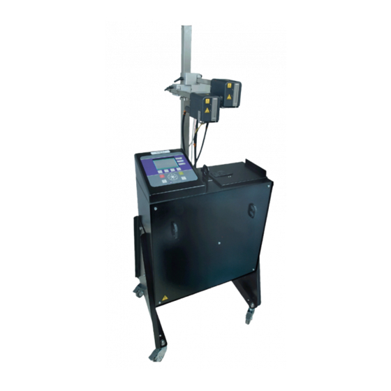
SECTION 1 General Information Welcome to the Model 5200/5400 The Model 5200 and 5400 are part of the 5000 Series of case coders, which use MARKEM Touch Dry® ink technology, and provide flexibility and quality in coding cases directly on your packaging line. -
Page 16: Glossary
SECTION 1 General Information Related Documentation • Model 5200/5400 Documentation Set ....0855847 • Model 5200/5400 Installation and Setup Guide ..0855848 •... -
Page 17: Specifications
SECTION 1 General Information Specifications Weight: Print station (not including umbilical lines) Model 5200: Approx. 63kg (140 lb) Model 5400: Approx. 77kg (170 lb) Printhead: Approx. 2.1kg (4.6 lb) Dimensions: See Dimensional Drawing (Paragraph 3.0) Noise Emission: Does not exceed 75 dB(A) Electrical Standards: CE marked ETL listed, conforms to ANSI/UL 60950 and... -
Page 18: Dimensional Drawing
SECTION 1 General Information Dimensional Drawing INCHES 43.6 25.5 57.8 21.7 21.7 11.2 12.2 15.8 48.3 64.8 146.85 55.1 55.1 1–4 0855855eng 6/08... -
Page 19: Safety Information
SECTION 1 General Information Safety Information The Model 5200/5400 has been designed to meet various safety standards. To alert you to potentially hazardous situations, labels and messages appear on the coder and throughout the guides. CAUTION refers to a potentially hazardous situation which, if not avoided, could result in personal injury. -
Page 20: Automatic Startup
SECTION 1 General Information Automatic Startup CAUTION Do not allow an automatic packaging machine startup after a Model 5200/5400 reset. Install the Model 5200/5400 Fault Relay output for a manual packaging machine reset. Automatic startup of a packaging machine could kill or seriously maim an operator. TECHNICAL ISSUE: The Model 5200/5400 has an optional feature which enables it to stop or prevent packaging machine operation when coder conditions prevent marking the packages. -
Page 21: Safety Labels
SECTION 1 General Information Safety Labels High Voltage To prevent injury from electrical shock, remove the power cord from the electrical outlet before performing troubleshooting or repair. Electronic troubleshooting must be performed by personnel trained to troubleshoot electrical circuits. Hot Surfaces To prevent injury from burns, be careful not to touch the jet array surface or hot ink directly. - Page 22 SECTION 1 General Information FRONT REAR 1–8 0855855eng 6/08...
-
Page 23: Foreseen Use
SECTION 1 General Information Foreseen Use The Model 5200/5400 is designed as an industrial case coder, intended for printing on corrugated containers. This coder was designed for or adapted by Markem-Imaje to a specific application at the time of sale. This application is the intended use. -
Page 24: Label And Symbol Identification
SECTION 1 General Information Label and Symbol Identification Serial/I.D./Rating Label This label is located on the rear of the enclosure and indicates the following: Model number Information about the coder Information about Markem-Imaje Patents covered Serial number CE mark Electrical specifications Attention symbol Electrical diagram number AC voltage configuration... - Page 25 SECTION 1 General Information CE Mark This symbol indicates that the coder meets safety and environmental requirements as defined in the European Directives. ETL Listed This label indicates that the coder conforms to ANSI/UL Standard 60950 and is certified to Canada/CSA C22.2 Standard 60950. Status This symbol is located near the STATUS LED on the user interface module, and indicates whether or not the coder is ready to print.
- Page 26 SECTION 1 General Information Optional Control Unit (OCU) This symbol indicates the interface device port that is used for bar code readers or a product ID reader. Serial Port This symbol indicates the serial ports. I0I0I (1) - Host (RS232, RS422, and RS485) I0I0I (2) - ASCII Comms (RS232) I0I0I (3) - Not Used (RS232) Printhead...
-
Page 27: Removal From Service
SECTION 1 General Information Removal from Service Follow these instructions to remove the coder from service. These instructions also pertain to transporting or storing the coder. Use the Shutdown menu to cool down and power off the coder. NOTE: Before moving the printhead, wait approximately two hours for the printhead to cool and the “Shut down”... - Page 28 SECTION 1 General Information 1–14 0855855eng 6/08...
-
Page 29: Basic Operation
SECTION 2 Basic Operation Model 5200/5400 Service Guide... -
Page 31: Basic Components
SECTION 2 Basic Operation Basic Components The coder consists of the print station (1, Figure 2-1), umbilical (2, Figure 2-1), printhead (3, Figure 2-1), and any options installed. The print station consists of the user interface module (4, Figure 2-1) and enclosure (5, Figure 2-1). The enclosure is the cabinet that houses the electrical components, vacuum pressure controller, and ink delivery module. - Page 32 SECTION 2 Basic Operation An umbilical (1, Figure 2-2), which consists of an ink line, vacuum line, and electrical line, connects each printhead to the print station. The operator inserts an ink bottle or an ink block through the ink door (2, Figure 2-2).
-
Page 33: The Power Switch
SECTION 2 Basic Operation The Power Switch The power switch (1, Figure 2-3) is located on the rear of the print station and is used to turn the coder on and off. The I position is ON. The 0 position is OFF. Figure 2–3 Powering On the Coder Turning the power switch to the I position powers on the coder and... -
Page 34: Powering Off The Coder
SECTION 2 Basic Operation Powering Off the Coder If the printhead is at operating temperature, the coder must be cooled down before turning the power switch off, or hot ink will weep from the jet array. The Shutdown feature is used to cool down the coder. -
Page 35: The User Interface Module
SECTION 2 Basic Operation The User Interface Module The display (1), keypad (2), and LED Indicators (3) are used to operate, program, and monitor the coder. Various menus will appear on the display. The Top Level menu is shown below. Job: Chocolate 25 Mar 2008 15:17:49 Status... -
Page 36: Led Indicators
SECTION 2 Basic Operation LED Indicators LED indicators on the user interface module are used to monitor the coder. The Top Level Menu provides messages to indicate the nature of the printing status, ink supply, and fault condition. The green STATUS LED indicates whether conditions are met for printing. -
Page 37: Navigation
SECTION 2 Basic Operation Navigation Various menus will appear on the display. The user navigates through the menus using the keypad. • Function keys (F1, F2, F3, F4) • ENTER and EXIT keys • START and STOP keys • Directional arrow keys ( On some menus, text must be entered into a text field. - Page 38 SECTION 2 Basic Operation 3.2.2 Function Keys The F1, F2, F3, and F4 keys are function keys. Pressing one of these keys selects the button described above it on the display. Depending on the menu, the available functions will vary. Function keys often open new menus.
-
Page 39: Select Characters Dialog Box
SECTION 2 Basic Operation 3.2.4 START and STOP Keys The green START key (3) is used to start printing. When printing, the coder is online. The red STOP key (4) is used to stop printing. When not printing, the coder is offline. 3.2.5 Directional Arrow Keys The directional arrow keys (5) are used to move the arrow on the... -
Page 40: Using The Keyboard
SECTION 2 Basic Operation 3.2.7 Using the Keyboard An optional keyboard may be used to navigate through menus and enter alphanumeric characters. NOTE: The keyboard layout varies, depending on the manufacturer and style. Your keyboard may differ from the one depicted below. Page Down F1 F2 F3 F4 Page Up... -
Page 41: The Printhead
SECTION 2 Basic Operation The Printhead Located on the front of the printhead is the jet array (1), where hot droplets of ink are ejected onto your carton or package. Located on the rear of the printhead are the umbilical ports, where the vacuum lines (2), electrical line (3), and ink line (4) are connected. - Page 42 SECTION 2 Basic Operation 2–12 0855855eng 6/08...
-
Page 43: Care And Cleaning
SECTION 3 Care and Cleaning Model 5200/5400 Service Guide... -
Page 45: Reliability Centered Maintenance
SECTION 3 Care and Cleaning Reliability Centered Maintenance To maximize performance and reliability of the coder and prolong its life, perform the following preventive maintenance procedures. To find the procedure, refer to the “explanation” column. The schedule is based on the number of 8-hour shifts per day that the coder is used: 8 hours, 16 hours, or 24 hours of operation. -
Page 46: Daily Cleaning Of The Printhead
SECTION 3 Care and Cleaning Daily Cleaning of the Printhead To ensure that the printhead operates reliably and to maintain print quality, it is necessary to clean ink and contaminants from the jet array daily, using the following procedures: • Purging •... -
Page 47: Purging
SECTION 3 Care and Cleaning Purging CAUTION: Hot Surfaces. To prevent injury from burns, be careful not to touch the jet array surface or hot ink directly. Wear protective eyeglasses when working with hot ink. Purging is the forcing of trapped air and hot ink through the jet array for a few seconds and is done periodically to clear the jet array. -
Page 48: Auto Purge Spacing Guidelines
SECTION 3 Care and Cleaning 2.1.2 Auto Purge Spacing Guidelines The Auto Purge feature is used to periodically purge the specified printhead without pressing the purge button. Set from the Machine Setup menu, an auto purge is triggered by the software and the duration is typically shorter than a regular purge. -
Page 49: Jet Testing
SECTION 3 Care and Cleaning Table 3–2 Spacing Guideline Purge Duration Purge Cycle Time 0.2 Sec. 2.75 Sec. 0.3 Sec. 3.625 Sec. 0.4 Sec. 3.75 Sec. 0.5 Sec. 3.875 Sec. 0.6 Sec. 4.0 Sec. 0.7 Sec. 4.125 Sec. 0.8+ Sec. 4.25 Sec. -
Page 50: Wiping
SECTION 3 Care and Cleaning 3. If any jets are not working properly, repeat the Purge and Jet Test procedures. DO NOT WIPE the jet array unless several attempts at purging are unsuccessful in recovering jets. Wiping CAUTION: Hot Surfaces. To prevent injury from burns, be careful not to touch the jet array surface or hot ink directly. -
Page 51: Cleanup
SECTION 3 Care and Cleaning Cleanup The coder meets the following International Protection / Ingress Protection (IP) international standards: Enclosure: IP45 (with doors latched) Printhead: IP43 Carton Sensor: IP65 Encoder: IP65 When washing down the packaging line, take special care to protect the coder. -
Page 52: Cleaning The Bottle Sensor And Reflective Tape
SECTION 3 Care and Cleaning Cleaning the Bottle Sensor and Reflective Tape The bottle sensor sends a beam to the reflective tape (Figure 3-1) to sense when an ink bottle is present in the bottle guide. It is recommended that the bottle sensor and reflective tape be cleaned every six months. -
Page 53: Stuck Bottle Removal
SECTION 3 Care and Cleaning Stuck Bottle Removal If the melt cycle is interrupted or a deformed bottle is inserted into the melt chamber, the fault message “Ink Bottle Stuck” (W241) may result. • Clear the fault message (W241) and let the next melt cycle complete the melting of the ink. - Page 54 SECTION 3 Care and Cleaning 3–10 0855855eng 6/08...
-
Page 55: Diagnostic Tools
SECTION 4 Diagnostic Tools Model 5200/5400 Service Guide... -
Page 57: Diagnostic Guidelines
SECTION 4 Diagnostic Tools Diagnostic Guidelines This section contains information to help you monitor operations and diagnose problems with the coder. Visual and auditory signs will provide diagnostic guidance. Signal lights and LED indicators on the user interface module and the rear of the printhead are designed to help you monitor operations and diagnose problems. -
Page 58: Signal Tower Lights
SECTION 4 Diagnostic Tools STATUS LED (green) Power is off Online Blinking Warming up or cooling down (fast blinking) or printhead is ready but offline (slow blinking) INK LED (blue) Ink level is okay Add ink Blinking Add ink immediately NOTE: After adding ink, it might be necessary to press the ENTER key to resume printing. -
Page 59: Led Indicator On The Printhead
SECTION 4 Diagnostic Tools LED Indicator on the Printhead An amber LED (1, Figure 4-1) located on the rear of the printhead provides a quick status check of the printhead. Figure 4–1 Printhead is enabled, ready to print, and there are no fault conditions. Printhead power is disconnected or Printhead is disabled or Printhead is purging. -
Page 60: Led Indicator On The Control Board
SECTION 4 Diagnostic Tools LED Indicator on the Control Board The amber LED indicator (1, Figure 4-2) is known as the “heartbeat LED.” On or Off Microprocessor is locked up Blinking Microprocessor is functioning NOTE: For a soft reset, use SW1 (2, Figure 4-2), which is a momentary switch that resets the microprocessor without cycling the power supplies in the machine. -
Page 61: Machine Diagnostics Menu
SECTION 4 Diagnostic Tools Machine Diagnostics Menu The Machine Diagnostics menus contain data that provide information about the coder. The actual menus and parameters that are displayed depend on access level. 1. From the Top Level menu, press F4 (Main Menu). 2. -
Page 62: Access Level
SECTION 4 Diagnostic Tools Access Level Access to various menus is restricted to different levels of users. The Access Level parameter is used to temporarily change the access level from the default to a different level. Most of the Machine Diagnostics menus require Level 3 access. Some menus can only be accessed by Markem-Imaje service personnel. -
Page 63: Ink System
SECTION 4 Diagnostic Tools Ink System The Ink System menus display the set point, actual value, and state of the ink system components. Ink system values can be read with Level 3 access. Set points can only be changed by Markem-Imaje service personnel. -
Page 64: Melt Temperature
SECTION 4 Diagnostic Tools 2.3.1 Melt Temperature Parameter Options: 0–140° C (default = 125); in 0.5° increments Access Level: Read–3; Write–4 The Melt Temp parameter is used to set the temperature of the ink melting chamber, and can only be changed by Markem-Imaje service personnel. -
Page 65: Printhead 1 - 4 Array Temperature
SECTION 4 Diagnostic Tools 2.3.5 Printhead 1 - 4 Array Temperature Parameter Options: 0–140° C (default = 125); in 0.5° increments Access Level: Read–3; Write–4 The PH Array Temp parameter is used to set the temperature of the specific printhead array, and can only be changed by Markem-Imaje service personnel. -
Page 66: Ink Pump
SECTION 4 Diagnostic Tools 2.3.9 Ink Pump Access Level: Read–3 The Ink Pump parameter counts the number of pump strokes. 2.3.10 Printhead 1 - 4 Low Vacuum Parameter Options: Vertical - 0.00–5.00 In. H 0 (default = 1.73) Horizontal - 0.00–5.00 In. H 0 (default = 2.13) Down - 0.00–5.00 In. -
Page 67: Printhead 1-4
SECTION 4 Diagnostic Tools Printhead 1 - 4 The Printhead menu is used to monitor printhead functioning and diagnose problems with each printhead. 2.4.1 State Parameter Options: On, Off, Standby Access Level: Read–3 The State parameter indicates the state of the printhead. 2.4.2 Parameter Options: OK, Low, Unknown Access Level: Read–3... -
Page 68: Reservoir Thermistor
SECTION 4 Diagnostic Tools 2.4.5 Reservoir Thermistor Parameter Options: -35–140° C Access Level: Read–3 The Reservoir Thermistor parameter indicates the actual printhead reservoir temperature and is based on reservoir heater set point. Note that -35° C indicates a failed thermistor. 2.4.6 Array Heater Parameter Options: On, Off... -
Page 69: Ink Line Heater
SECTION 4 Diagnostic Tools 2.4.9 Ink Line Heater Parameter Options: On, Off Access Level: Read–3; Write–3 The Ink Line Heater parameter indicates whether power to the ink line heater is turned on or off. 2.4.10 Ink Line Current Parameter Options: On, Off Access Level: Read–3 The Ink Line Current parameter indicates whether the ink line heater circuit is complete so that current is flowing through it. -
Page 70: Printhead Lamp
SECTION 4 Diagnostic Tools 2.4.13 Printhead Lamp Parameter Options: On, Off Access Level: Read–3; Write–3 The Printhead Lamp parameter indicates the state of the amber LED on the printhead. 2.4.14 Encoder Speed Access Level: Read–3 The Encoder Speed parameter indicates the speed of the conveyor/ product. -
Page 71: Ink Delivery Module
SECTION 4 Diagnostic Tools Ink Delivery Module The Ink Delivery Module menu is used to monitor functioning and diagnose problems with the ink delivery module. 2.5.1 State Parameter Options: No Heads, Warming Up, Ready Access Level: Read–3 "No Heads" - No printheads are enabled or connected. "Warming Up"... -
Page 72: Melt Thermistor
SECTION 4 Diagnostic Tools 2.5.4 Melt Thermistor Parameter Options: 55–125° C Access Level: Read–3 The Melt Thermistor parameter indicates the temperature of the ink melt chamber. The set point is 125° C. Typical range is 115–125° C during melt cycle and 55–60° C during idle state. This value can vary as the melt chamber is melting or cooling. -
Page 73: Hold Thermistor
SECTION 4 Diagnostic Tools 2.5.8 Hold Thermistor Parameter Options: Shutdown/Auto Shutdown, Warming Up, Ready Access Level: Read–3 "Shutdown"/"Auto Shutdown" - System is in shutdown state. "Warming Up" - A melt cycle is in progress. "Ready" - System is up to temperature and stabilized. 2.5.9 Hold Heater Parameter Options: On, Off... -
Page 74: Pump Motor
SECTION 4 Diagnostic Tools 2.5.12 Pump Motor Parameter Options: On, Off Access Level: Read–3; Write–3 The Pump Motor parameter indicates whether the motor is energized and pumping ink to printhead(s). 2.5.13 Pump Cycle Time Parameter Options: Time in seconds Access Level: Read–3 The Pump Cycle Time parameter reports the time it takes for one revolution of the ink pump motor, and indicates relative loading of the ink filter or any restriction/cold spot in the ink delivery system. -
Page 75: Filter Usage Count
SECTION 4 Diagnostic Tools 2.5.16 Filter Usage Count Access Level: Read–3 The Filter Usage Count parameter indicates the number of ink pump strokes between the upper and lower ILS, which on a new filter will take approximately 400 strokes. When the number is too large, the system will generate a printhead supply warning and will recommend replacing the filter. -
Page 76: Enclosure Temperature
SECTION 4 Diagnostic Tools 2.6.4 Enclosure Temperature Access Level: Read–3 The Enclosure Temperature parameter displays the ambient temperature inside the enclosure at the circuit boards. Machine problems may occur if this temperature exceeds 60° C. 2.6.5 Product Sensor 1 and 2 (PS1 and PS2) Parameter Options: Active, Inactive Access Level: Read–3 The Product Sensor parameter displays the status of each product... -
Page 77: Vpc 1-2 And 3-4
SECTION 4 Diagnostic Tools VPC 1-2 and 3-4 The VPC 1-2 and VPC 3-4 menus are used to test the functioning of the respective VPC. VPC 1-2 supports Printheads 1 and 2; VPC 3-4 supports Printheads 3 and 4. 2.7.1 High Vacuum Pump Parameter Options: On, Off Access Level: Read–3;... -
Page 78: High Vacuum Minimum Run Time
SECTION 4 Diagnostic Tools 2.7.4 High Vacuum Minimum Run Time Parameter Options: Time in Seconds; 0-25 (Default = 5 Seconds) Access Level: Read–3; Write–3 The High Vac Min Run Time parameter reports the amount of time the high vacuum pump is turned on to maintain vacuum level. When the High Vac Min Run Time is set to zero, the high vacuum system will be disabled. -
Page 79: Low Vacuum Duty Cycle 2 And 4
SECTION 4 Diagnostic Tools 2.7.8 Low Vacuum 2 and 4 Parameter Options: 0-5 In. H Access Level: Read–3 The Low Vacuum parameter reports the value in inches of water of low vacuum to printhead 2 (VPC 1-2) or printhead 4 (VPC 3-4), and depends on printhead orientation. -
Page 80: Beeper
SECTION 4 Diagnostic Tools 2.8.2 Beeper Parameter Options: On, Off Access Level: Read–3; Write–3 The Beeper parameter indicates whether the key beeper is on or off. 2.8.3 Status Lights Parameter Options: On, Off Access Level: Read–3; Write–3 The Status Lights parameter indicates whether a status light is on or off. -
Page 81: Ocu
SECTION 4 Diagnostic Tools The OCU menu is used to monitor functioning and diagnose problems with the Optional Control Unit (OCU). The OCU provides the capability to interface the coder with up to two verification readers and one Product ID reader. Refer to OCU Installation Instructions P/N 084079 for detailed information on programming and operating bar code scanners. -
Page 82: Reader Sensor (1 And 2)
SECTION 4 Diagnostic Tools 2.9.2 Reader Sensor (1 and 2) Parameter Options: On, Off Access Level: Read–3 The Reader Sensor parameter indicates whether a carton is currently seen by the carton sensor connected to Product Sensor Reader 1 or 2 port of the OCU unit and triggers the Reader 1 or 2 bar code scanner to read. -
Page 83: Product Id Sensor
SECTION 4 Diagnostic Tools 2.9.5 Product ID Sensor Parameter Options: On, Off Access Level: Read–3 The Product ID Sensor parameter indicates whether a carton is currently seen by the carton sensor connected to the Product Sensor I.D. port of the OCU unit and triggers the Product ID (TU Lookup) bar code scanner to read. -
Page 84: Ink Usage
SECTION 4 Diagnostic Tools 2.10 Ink Usage The Ink Usage menu is used to determine the amount of ink that is being used for the selected job. 2.10.1 Job Prints Per Bottle Access Level: Read–3 The Job Prints Per Bottle parameter reports the total number of images that can be printed with one bottle of ink using the specified number of printheads with the job selected. -
Page 85: Imaging/Printing
SECTION 4 Diagnostic Tools 2.11 Imaging/Printing The Imaging/Printing menu shows the time that it takes to render or print any selected image. Various types of data are generated. 2.11.1 Activate Timing Parameter Options: On, Off Access Level: Read–3; Read–3 When the Activate Timing parameter is On, data is captured for the categories listed below. -
Page 86: Printing (Head 1-4)
SECTION 4 Diagnostic Tools 2.11.4 Printing (Head 1-4) Access Level: Read–3 When Activate Timing is On, the Printing parameter reports the time spent by the FPGA actually printing a single printhead's image from the point the FPGA is told to begin until the FPGA interrupts to say it is done. -
Page 87: Remote Variable Fields
SECTION 4 Diagnostic Tools 2.11.8 Remote Variable Fields Access Level: Read–3 When Activate Timing is On, the Remote Variable Fields parameter reports the time it takes to process a remote Update Variable Fields message (ASCII Comms or Host port). The time includes the following: •... -
Page 88: State Logger
SECTION 4 Diagnostic Tools 2.12 State Logger Access Level: Read–3 This screen records software state information for various state machines that is used in the firmware. The information is useful to the engineering teams to diagnose system issues. 2.13 Action Logger Access Level: Read–3 The Action Logger screen records the actions taken by the user. -
Page 89: Troubleshooting
SECTION 5 Troubleshooting Model 5200/5400 Service Guide... -
Page 91: Troubleshooting Guidelines
SECTION 5 Troubleshooting Troubleshooting Guidelines CAUTION: Electrical and electronic troubleshooting must be performed by personnel trained to troubleshoot electrical circuits. Personnel are endangered when they exceed the limitations of their training. Electronic components are sensitive to electrostatic discharge (ESD). Take the necessary precautions when handling subassemblies. -
Page 92: Troubleshooting Chart
SECTION 5 Troubleshooting Troubleshooting Chart The Troubleshooting Chart lists symptoms and possible causes or problems. In most cases the recommended action is a reference to the appropriate procedure in the 5200/5400 documentation set. References 2-character abbreviation of document, section number, paragraph title Example OP, 3, Selecting a Job = Operation Guide, Section 3,... -
Page 93: Not Printing
SECTION 5 Troubleshooting Symptom Possible Cause / Problem Reference / Action Not Printing Printhead(s) not enabled IN, 3, PH Enable Job not selected OP, 3, Selecting a Job Machine not online OP, 2, LED Indicators Incorrect print registration OP, 3, Setting the Registration IN, 3, Registration/Spacing Product sensor not functioning OP, 3, Setting the Registration... - Page 94 SECTION 5 Troubleshooting Symptom Possible Cause / Problem Reference / Action Smudged / blurred Product contacting printhead IN, 2, Mounting the Printhead print (continued) Ink can build up on the front of the printhead. If a product passes closely in front of the printhead, the liquid ink can transfer to the product, distorting the printed image.
-
Page 95: Cannot Purge Printhead
SECTION 5 Troubleshooting Symptom Possible Cause / Problem Reference / Action Ink Weeping / Printhead ink soak (ink in the Printhead Soak Kit Dripping from the low vacuum line) Instructions 0840546 Printhead Incorrect printhead position / IN, 3, PH Orientation incorrect vacuum setting IN, 3, Printhead Vacuum Settings... -
Page 96: Cannot Jet Test Printhead
SECTION 5 Troubleshooting Symptom Possible Cause / Problem Reference / Action Printhead not Defective Head Interface SE, 6, Replacing the functioning (continued) Board Printhead Defective printhead SE, 6, Replacing the Printhead Cannot Jet Test Printhead not enabled SE, 4, LED Indicator on the Printhead Printhead IN, 3, PH Enable... -
Page 97: Enclosure Ink Leak
SECTION 5 Troubleshooting Symptom Possible Cause / Problem Reference / Action Printhead Will Not Printhead not enabled SE, 4, LED Indicator on the Heat Printhead IN, 3, PH Enable SE, 4, Printhead 1-4; State Corrupted array or reservoir IN, 3, Array Temperature temperature set point IN, 3, Reservoir Temperature Electrical connection... -
Page 98: Cannot Read Display
SECTION 5 Troubleshooting Symptom Possible Cause / Problem Reference / Action Ink Delivery Module Holding chamber Check that the filter screws (IDM) (continued) are tightly secured to the holding chamber. Check for broken filter O-ring. Replace if necessary. Check for broken pump piston O-ring. - Page 99 SECTION 5 Troubleshooting Symptom Possible Cause / Problem Reference / Action Heartbeat LED on Corrupted RAM Reset to factory default. Control Board blinks NOTE: Resetting RAM will (continued) result in a loss of parameters. If running Rev L software or lower, loss of job files will also result.
-
Page 100: Machine Will Not Power Up
SECTION 5 Troubleshooting Symptom Possible Cause / Problem Reference / Action Power supply problem Test for proper DC voltages on Machine Will Not backplane and control board. DC voltages on Control Board Power Up (Continued) Backplane Schematic Open F7 fuse on Backplane Machine Resets Temporary power interruption Ensure that conditions are met... -
Page 101: Job Not Found
SECTION 5 Troubleshooting Symptom Possible Cause / Problem Reference / Action Job Not Found Incorrect default database path Verify proper path and using CimControl directory. Job file not saved properly Save job file again. Select job. OP, 3, Selecting a Job IN, 4, The Database Management Menu Incomplete download... - Page 102 SECTION 5 Troubleshooting 5–12 0855855eng 6/08...
-
Page 103: Field Replaceable Parts
SECTION 6 Field Replaceable Parts Model 5200/5400 Service Guide... -
Page 105: Proper Handling Of A Circuit Board
SECTION 6 Field Replaceable Parts Proper Handling of a Circuit Board Many of the replacement procedures require working with circuit boards. When handling a circuit board, observe the following: • Circuit boards are electronically sensitive and can be damaged by electrostatic discharges (ESD). To prevent damage, use industry-approved methods and wear a grounded wrist strap. -
Page 106: Replacement
SECTION 6 Field Replaceable Parts Replacement Remove the low vacuum tube of the new VPC from the same fitting location that was left empty on the old VPC. Connect the tubing that came from the old tee to the tee of the new VPC. -
Page 107: Replacing The User Interface Module (Uim)
SECTION 6 Field Replaceable Parts Replacing the User Interface Module (UIM) What You Will Need • Large flathead screwdriver • #2 Phillips screwdriver (8” [203mm] long shaft minimum) Preparation Power off the Model 5200/5400 and disconnect the power cable. Remove the front cover by loosening the five large captive screws. - Page 108 SECTION 6 Field Replaceable Parts Figure 6–2 Replacement Reverse the steps taken in Removal, paragraph 2.3. NOTE: Do not pinch the cables below the user interface module. Align the edges of the user interface to the edges of the control box.
- Page 109 SECTION 6 Field Replaceable Parts Figure 6–3 Final Steps When paragraphs 2.2 through 2.4 are complete: Install the front cover. NOTE: The ground wire may need to be connected to the print station first. Connect the power cable and power on the Model 5200/5400. 6–5 0855855eng 6/08...
-
Page 110: What You Will Need
SECTION 6 Field Replaceable Parts Replacing the Printhead What You Will Need • Phillips screwdriver • Allen wrench Preparation Disable the printhead in the Setup menu. Power off the Model 5200/5400 and disconnect the power cable. Let the printhead cool for about two hours before handling it. Removal Disconnect the ground screw (1, Figure 6-4). - Page 111 SECTION 6 Field Replaceable Parts Final Steps When paragraphs 3.2 through 3.4 are complete: Connect the power cable and power on the Model 5200/5400. The cold printhead requires 15 minutes to heat. When the printhead is nearly ready, tighten the ink line fitting. When the printhead is ready, perform a purge and jet test.
-
Page 112: What You Will Need
SECTION 6 Field Replaceable Parts Replacing the Ink Delivery Module (IDM) NOTE: This procedure should not be done while the IDM is hot. Allow the IDM to cool before beginning. What You Will Need • 4mm Allen wrench • Large flathead screwdriver •... - Page 113 SECTION 6 Field Replaceable Parts Replacement 1. Loosen the four bottom screws on the new IDM before setting the new IDM in the enclosure. 2. To install the IDM, reverse the steps in Removal, paragraph 4.3. 3. For details, see Section 6, Replacing the Ink Line. NOTE: Be careful when plugging the two IDM connectors into the backplane board.
-
Page 114: What You Will Need
SECTION 6 Field Replaceable Parts Replacing the Ink Level Sensor (ILS) in the IDM This procedure is best performed while the IDM is hot. NOTE: The ILS in the IDM is a float sensor that is also called the upper ILS, lower ILS, upper float sensor, and lower float sensor. What You Will Need •... - Page 115 SECTION 6 Field Replaceable Parts Figure 6–7 3. Remove the three ILS wire leads from the connector, noting which wire color goes to which terminal. 4. Using wire cutters, remove wire ties as needed. 5. Loosen the bottle guide, and slide it down on the melt chamber. Tighten the bottle guide into place.
- Page 116 SECTION 6 Field Replaceable Parts Replacement 1. Install the wire leads into the appropriate terminals and tighten. Note Pin #1 (1, FIgure 6-9). Use Table 6-1 for guidance. Figure 6–9 Table 6–1 IDM Connector Pins Pin # Function RED MELT THERMISTOR (1, Figure 6-9) RED MELT THERMISTOR RED HOLDING THERMISTOR RED HOLDING THERMISTOR...
- Page 117 SECTION 6 Field Replaceable Parts 2. Route the wire harness back through the wire duct. 3. Install the new ink level sensor to the heat shield, using a 5/8 inch open-end wrench on the top nut and a 9/16 open-end wrench on the bottom nut.
-
Page 118: What You Will Need
SECTION 6 Field Replaceable Parts Replacing the Ink Pump Motor and Ink Pump Piston NOTE: This procedure is best performed when the ink delivery module is hot. What You Will Need • 2mm Allen wrench • 2.5mm Allen wrench • Phillips screwdriver •... - Page 119 SECTION 6 Field Replaceable Parts Figure 6–12 3. Carefully cut the wire ties from the wire harness leading to the connector, and remove the motor (FIgure 6-13). Figure 6–13 6–15 0855855eng 6/08...
- Page 120 SECTION 6 Field Replaceable Parts 4. Remove the wire harness from the wire duct under the transformer (1, Figure 6-14). Figure 6–14 5. Disconnect the green connector (J) from the back panel circuit board (1, Figure 6-15). Figure 6–15 6. Remove the two ink pump motor wire leads from the connector, noting which wire color goes to which terminal.
-
Page 121: Replacement
SECTION 6 Field Replaceable Parts Replacement 1. Install the new motor to the motor bracket. Install with the washers and screws previously removed and tighten securely. 2. Place the piston back into the ink pump hole. 3. Install the eccentric on the motor shaft and ensure that the piston is properly seated on the eccentric. -
Page 122: Replacing The Idm Filter
SECTION 6 Field Replaceable Parts Replacing the IDM Filter The filter replacement kit (1060978) provides a new IDM filter and two new O-rings. This procedure is best performed while the IDM is hot. What You Will Need • 2.5mm Allen wrench •... -
Page 123: Replacement
SECTION 6 Field Replaceable Parts CAUTION: Hot Surfaces. The filter can be hot. To prevent injury from burns, use a protective glove or pliers when removing the filter. Figure 6–17 Replacement 1. Install the two new O-rings on the new filter. Place the new filter into the opening, and gently push the filter in by pushing in the center of the filter top. -
Page 124: Replacing The Ink Line
SECTION 6 Field Replaceable Parts Replacing the Ink Line What You Will Need • 1/2 inch open-end wrench • 5/8 inch or 7/8 inch open-end wrench Preparation 1. Power off the Model 5200/5400 and disconnect the power cable. 2. Let the print station and printhead cool for about two hours. Removal 1. -
Page 125: Final Steps
SECTION 6 Field Replaceable Parts Final Steps When paragraphs 8.2 through 8.4 are complete: 1. Reconnect the power cable and power on the Model 5200/5400. CAUTION: High voltage is present in the print station enclosure. 2. When the printhead is warm, retighten the printhead connection. 3. -
Page 126: Replacing The Control Board
SECTION 6 Field Replaceable Parts Replacing the Control Board 10.1 What You Will Need • Large flathead screwdriver • Antistatic wrist strap • Static-shielding bag 10.2 Preparation Power off the Model 5200/5400 and disconnect the power cable. Remove the front cover by loosening the five large captive screws. -
Page 127: Final Steps
SECTION 6 Field Replaceable Parts Figure 6–18 10.5 Final Steps When paragraphs 9.2 through 9.4 are complete: Install the front cover. NOTE: The ground wire may need to be connected to the print station first. Connect the power cable and power on the Model 5200/5400. 6–23 0855855eng 6/08... -
Page 128: Replacing The Printhead Volt Board
SECTION 6 Field Replaceable Parts Replacing the Printhead Volt Board 11.1 What You Will Need • Large flathead screwdriver • #1 Phillips screwdriver • Antistatic wrist strap • Static-shielding bag 11.2 Preparation Power off the Model 5200/5400 and disconnect the power cable. - Page 129 SECTION 6 Field Replaceable Parts Figure 6–19 NOTE: Before removing the printhead volt board, take note of how the two ribbon cables are folded behind the printhead volt board to be able to repeat the same folding when installing the new printhead volt board.
-
Page 130: Replacement
SECTION 6 Field Replaceable Parts 11.4 Replacement 1. Reverse the steps in Removal, paragraph 10.3, to install the new printhead volt board. 11.5 Final Steps When paragraphs 10.2 through 10.4 are complete: 1. Install the front cover. NOTE: The ground wire may need to be connected to the print station first. -
Page 131: Replacing The I/O Panel Assembly
SECTION 6 Field Replaceable Parts Replacing the I/O Panel Assembly 12.1 What You Will Need • Large flathead screwdriver • #1 Phillips screwdriver • Antistatic wrist strap • Static-shielding bag • Access to the I/O door 12.2 Preparation 1. Power off the Model 5200/5400 and disconnect the power cable. 2. - Page 132 SECTION 6 Field Replaceable Parts 3. Place the control board in the static-shielding bag and close the bag. 4. Unplug the transformer connector from the printhead volt board (2, Figure 6-21). 5. Unplug the ink line connector(s) from the printhead volt board. If it is not already marked, mark on the orange tag on the ink lines the number written on the corresponding connectors (3, Figure 6-21) on the printhead volt board.
- Page 133 SECTION 6 Field Replaceable Parts Figure 6–23 Figure 6–24 6–29 0855855eng 6/08...
-
Page 134: Replacement
SECTION 6 Field Replaceable Parts 12.4 Replacement Reverse the steps in Removal, paragraph 11.3, to install the new I/O panel assembly. 12.5 Final Steps When paragraphs 11.2 through 11.4 are complete: Install the front cover. NOTE: The ground wire may need to be connected to the print station first. -
Page 135: Replacing The Transformer(S)
SECTION 6 Field Replaceable Parts Replacing the Transformer(s) 13.1 What You Will Need • Large flathead screwdriver • 13mm closed-end offset wrench 13.2 Preparation 1. Power off the Model 5200/5400 and disconnect the power cable. 2. Remove the front cover by loosening the five large captive screws. -
Page 136: Replacement
SECTION 6 Field Replaceable Parts 13.4 Replacement 1. Reverse the steps in Removal, paragraph 12.3. 2. After the plugs are connected, make sure the wires running up from the transformer (if in the bottom position) route up behind the fan (5, Figure 6-25). 3. -
Page 137: Replacing The Soft Start Board
SECTION 6 Field Replaceable Parts Replacing the Soft Start Board 14.1 What You Will Need • Large flathead screwdriver • #1 Phillips screwdriver 14.2 Preparation Power off the Model 5200/5400 and disconnect the power cable. Remove the front cover by loosening the five large captive screws. -
Page 138: Replacement
SECTION 6 Field Replaceable Parts Figure 6–26 14.4 Replacement Reverse the steps in Removal, paragraph 13.3. After the plug(s) are connected, make sure the wires running up from the transformer (if in the bottom position) route up behind the fan (5, Figure 6-26). NOTE: Make sure none of the wires will interfere with the operation of the fan blades. -
Page 139: Replacing The Vacuum/Ground Line
SECTION 6 Field Replaceable Parts Replacing the Vacuum/Ground Line 15.1 What You Will Need • #2 Phillips screwdriver • Wire cutters for wire ties 15.2 Preparation 1. The Model 5X00 can remain powered during this procedure. 15.3 Removal NOTE: To prevent damage to the O-ring, be sure to press the release on the quick disconnect when disconnecting or connecting vacuum lines. -
Page 140: Replacing The Printhead Data Cable
SECTION 6 Field Replaceable Parts Replacing the Printhead Data Cable 16.1 What You Will Need • No tools are required 16.2 Preparation Power off the Model 5200/5400 and disconnect the power cable. 16.3 Removal Disconnect the data cable from the back of the printhead. Open the access door on the back of the print station enclosure. -
Page 141: Spare Parts Kit
SECTION 6 Field Replaceable Parts Spare Parts Kit This procedure describes how to replace components that are included in the Spare Parts Kit. You will need the following tools. • #1 and #2 Phillips screwdrivers • 3mm and 4mm Allen wrenches •... -
Page 142: Melt Chamber Thermistor
SECTION 6 Field Replaceable Parts To replace the thermistor, reverse steps 1 through 3 above. NOTE: Be careful plugging the connector into the backplane, as it is possible to plug one pitch position off. Figure 6–27 17.3.2 Melt Chamber Thermistor Remove the ink delivery module. -
Page 143: Cartridge Heater With Thermostat
SECTION 6 Field Replaceable Parts 17.4 Cartridge Heater with Thermostat The cartridge heater may need to be replaced in two places located in the ink delivery module. See Section 6, Replacing the Ink Delivery Module. • Holding Chamber (1, Figure 6-27) •... -
Page 144: Melt Chamber Cartridge Heater With Thermostat (200W)
SECTION 6 Field Replaceable Parts 17.4.2 Melt Chamber Cartridge Heater with Thermostat (200W) 1. Remove the ink delivery module. See Section 6, Replacing the Ink Delivery Module and the Ink Delivery Module parts illustration. 2. Disassemble the melt chamber assembly from the heat shield by removing the two screws. -
Page 145: Replacing The Pump Stroke Counter Limit Switch
SECTION 6 Field Replaceable Parts 17.5.2 Replacing the Pump Stroke Counter Limit Switch 1. Remove the ink delivery module. See Section 6, Replacing the Ink Delivery Module and the Ink Delivery Module parts illus- tration. 2. Remove the limit switch (Figure 6-29) off the motor by unfastening the two screws, two split lock washers and two hex nuts. -
Page 146: Fuse Kit
SECTION 6 Field Replaceable Parts 17.7 Fuse Kit The fuse kit (0688415) provides replacement fuses for the backplane board and Printhead Volt Board. Use only Markem-Imaje specified fuses. 17.7.1 Fuses on Backplane Board To access the backplane board (0672529), see Section 6, Replacing the I/O Panel Assembly. -
Page 147: Fuses On Printhead Volt Board
SECTION 6 Field Replaceable Parts 17.7.2 Fuses on Printhead Volt Board There are two possible printhead volt boards; check part number. To access the printhead volt board, see Section 6, Replacing the Printhead Volt Board. Printhead Volt II Assembly (0672622, 0553335) Fuse (F1) GDC-5.0Amp, Time-Delay, 5 x 20mm F1 is a time-delay fuse used to protect the High Voltage power supply that provides strobe voltage to Printhead 1 and 2 against... -
Page 148: Fuse On Vpc Board
SECTION 6 Field Replaceable Parts 17.7.3 Fuse on VPC Board The fuse on the VPC board is not replaceable. To access the VPC board, see Section 6, Replacing the VPC Module. Fuse (F1) PTC RXE185 3.70Amp @ 50C FR1 is self-resetting and is used to protect the +24VDC power line to the low vacuum pump motor, high vacuum pump motor, and solenoid air values against shorts or over current. -
Page 149: Printhead Soak Kit
SECTION 6 Field Replaceable Parts Figure 6–31 Cut, strip and route the wires and install them into the connector (3, Figure 6-31). Note the connections for printhead 1 (4, Figure 6-31) and printhead 2 (5, Figure 6-31) Reinstall the VPC module. See Section 6, Replacing the VPC Module.
Need help?
Do you have a question about the markem-imaje 5200 and is the answer not in the manual?
Questions and answers
How turn up heat on printer heads? On the Markem 5400 printer