Table of Contents
Advertisement
Advertisement
Table of Contents

Related Manuals for Yale MPB045VG


Summary of Contents for Yale MPB045VG
- Page 2 COMPOSITION SPECIAL EQUIPMENT OR ATTACHMENTS © Yale Material Handling Corporation 2019. All Rights Reserved. YALE and VERACITOR are Registered Trademarks of Hyster-Yale Group, Inc. CSS, PREMIER, and are Trademarks in the United States and certain jurisdictions. is a registered copyright.
-
Page 3: Foreword
NOTE: A comprehensive operator training program is avail- 12/98, in the proper operation of THIS lift truck. able from Yale Company. For further details, contact your dealer for Yale Company lift trucks. • Understand the capabilities and limitations of the lift truck. - Page 4 On the lift truck, the WARNING symbol and word are on Operations, from the National Safety Council). orange background. The CAUTION symbol and word • Guide for Users of Industrial Lift Trucks (Yale Part No. are on yellow background. 550038777) describes lift truck safety, good mainte- nance practices, and training programs and is available from your dealer for Yale Company lift trucks.
-
Page 5: Table Of Contents
Contents Contents Foreword ..............Maintenance ..............46 TO OWNERS, USERS, AND OPERATORS: ..... HOW TO MOVE A DISABLED LIFT TRUCK ....46 Warning ................ HOW TO PUT A LIFT TRUCK ON BLOCKS ....47 Model Description ............Maintenance Schedule ..........48 GENERAL .............. -
Page 6: Warning
Warning WARNING FAILURE TO FOLLOW THESE INSTRUCTIONS CAN CAUSE SERIOUS INJURY OR DEATH! AUTHORIZED, TRAINED OPERATOR ONLY! KNOW YOUR TRUCK: • Do not ride truck unless it is designated as a rider type truck by manufacturer. • Do not operate or repair truck unless trained and author- ized. - Page 7 Warning WARNING FAILURE TO FOLLOW THESE INSTRUCTIONS CAN CAUSE SERIOUS INJURY OR DEATH! AUTHORIZED, TRAINED OPERATOR ONLY! • Handle loads only within capacity and load center shown • Always face direction of travel. on the Nameplate. • WHEN WALKING, control truck with one hand, using •...
- Page 8 Warning WARNING FAILURE TO FOLLOW THESE INSTRUCTIONS CAN CAUSE SERIOUS INJURY OR DEATH! AUTHORIZED, TRAINED OPERATOR ONLY! USE SPECIAL CARE WHEN OPERATING ON RAMPS: TAKE CARE WHEN CHARGING: • Travel slowly and do not angle or turn. Always travel with •...
-
Page 9: Model Description
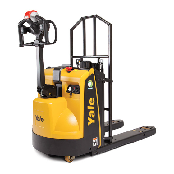
A detailed operating instruction is provided in the Operat- ing Procedures section of this manual. The Yale MPB045VG lift trucks are pedestrian-operated lift The operator has a choice of three performance modes trucks with lifting capacities of 2,041 kg (4,500 lb). - Page 10 Model Description CONTROL HANDLE CENTER COVER EMERGENCY POWER DISCONNECT FORK BATTERY COMPARTMENT DRIVE COMPARTMENT COVER OPERATING MANUAL Figure 1. Standard Model View Showing Major Components...
- Page 11 Model Description DELIVERY HANDLE OPERATING MANUAL CENTER COVER EMERGENCY POWER DISCONNECT DRIVE COMPARTMENT COVER MOVEABLE LOAD BACKREST LOAD RETENTION STRAP BATTERY COMPARTMENT FORK Figure 2. Retail Delivery Model View Showing Major Components...
-
Page 12: Nameplate
Model Description Nameplate The lift truck serial number code is on the Nameplate. The serial number code is also stamped on the lift truck frame. WARNING Any change to the lift truck or its equipment can change the lifting capacity. If the Nameplate does not show the maximum capacity, or if the lift truck equip- ment, including the battery, does not match that shown on the Nameplate, then the lift truck must NOT be oper-... - Page 13 Model Description Figure 4. Warning and Safety Labels...
- Page 14 Model Description Legend for Figure 4 NAMEPLATE YALE BLACK DECAL DECAL WARNING E-STOP LABEL PATENTS & TRADEMARKS LABEL WARNING LABEL OPERATING MANUAL...
-
Page 15: Instruments And Controls
Model Description Instruments and Controls Figure 5. Instruments and Controls... - Page 16 Model Description Legend for Figure 5 STANDARD TRUCK RETAIL DELIVERY TRUCK CONTROL HANDLE ARM DISPLAY - BATTERY INDICATOR/HOURMETER CONTROL HEAD ASSEMBLY DELIVERY HANDLE ARM EMERGENCY POWER DISCONNECT DELIVERY CONTROL HEAD ASSEMBLY KEY SWITCH MOVABLE LOAD BACKREST...
- Page 17 Model Description Table 1. Instruments and Controls (See Figure 5) Item Item Function Control Handle Move the control handle to the right or left to steer the truck. Fully raise or fully lower the control handle to engage the brake. When the control handle is released from the operating position, it will automatically return to the ver- tical position and engage the brake.
- Page 18 Model Description Table 1. Instruments and Controls (See Figure 5) (Continued) Item Item Function Selectable Performance Modes The user has a choice of three performance modes that are selectable through the control handle. The mode selection is made at startup, or key ON.
- Page 19 Model Description Table 1. Instruments and Controls (See Figure 5) (Continued) Item Item Function Selectable Performance Modes NOTE: See the section Operating Techniques for instructions on changing (Continued) performance mode setting.
- Page 20 Model Description Table 1. Instruments and Controls (See Figure 5) (Continued) Item Item Function Control Head Assembly The control handle assembly has the following controls: (a) Traction Reverse button (b) Horn button (c) Direction and speed control (d) Slow speed button (e) Lower button (f) Lift button NOTE: Operation of these controls is described in the following paragraphs.
- Page 21 Model Description Table 1. Instruments and Controls (See Figure 5) (Continued) Item Item Function Traction Reverse Button WARNING The traction reverse button causes rapid acceleration and should not be used for changing direction. The traction reverse button is on the end of the control handle. When the button is pushed, the lift truck will move away from the operator (forks first).
- Page 22 Model Description Table 1. Instruments and Controls (See Figure 5) (Continued) Item Item Function Speed/Direction Control The speed/direction control is for selecting forward or reverse movement and the travel speed of the lift truck. The control automatically returns to the OFF position when released.
- Page 23 Model Description Table 1. Instruments and Controls (See Figure 5) (Continued) Item Item Function Slow Speed Button The turtle button or slow speed mode enables the truck to operate at a slower limited top speed. This function is available in handle regions A, B, and C. Reference Figure 8 For operation in regions A and C, select and hold the turtle button then rotate the speed/direction control in the direction of desire travel.
- Page 24 Model Description Table 1. Instruments and Controls (See Figure 5) (Continued) Item Item Function Lower Press the button to lower the forks. Release the button to stop lowering. Button...
- Page 25 Model Description Table 1. Instruments and Controls (See Figure 5) (Continued) Item Item Function Lift Button Press the button to raise the forks. Release the button to stop lifting. If the truck is trying to lift too much weight, the hydraulic system will go into bypass and the controller will shut off the hydraulic motor.
- Page 26 Model Description Table 1. Instruments and Controls (See Figure 5) (Continued) Item Item Function Emergency Power Disconnect The emergency power disconnect is located on top of the cowl. Push the button to interrupt power supply. Key Switch The key switch is located on the operator's display panel. The key switch has two positions: O and I.
- Page 27 Model Description Table 1. Instruments and Controls (See Figure 5) (Continued) Item Item Function Battery Indicator/Hourmeter A combination hourmeter, battery state of charge, and fault indicator is pro- vided on this lift truck and includes a diagnostic fault code display. The hour- meter continually displays total operation hours when the key switch is ON and current is flowing.
- Page 28 Model Description Table 1. Instruments and Controls (See Figure 5) (Continued) Item Item Function Delivery Handle This ergonomically optimized design of the retail delivery handle allows the operator full command of the truck's functionality with the handle in full upright position. With the handle in upright position the truck can be operated in the most compact configuration for maximum maneuverability and visibility.
- Page 29 Model Description Table 1. Instruments and Controls (See Figure 5) (Continued) Item Item Function Delivery Handle Head Assembly The delivery handle head assembly has the following controls: (g) Traction Reverse button (h) Horn Button (j) Direction and Speed control (k) Lower button (m) Lift button (n) Traction switch (o) Traction Interlock...
- Page 30 Model Description Table 1. Instruments and Controls (See Figure 5) (Continued) Item Item Function Traction Reverse Button WARNING The traction reverse button causes rapid acceleration and should not be used for changing direction. The traction reverse button is on the end of the delivery handle. When the button is pushed, the lift truck will move away from the operator (forks first).
- Page 31 Model Description Table 1. Instruments and Controls (See Figure 5) (Continued) Item Item Function Speed/Direction Control The speed/direction control is for selecting forward or reverse movement and the travel speed of the lift truck. The control automatically returns to the OFF position when released.
- Page 32 Model Description Table 1. Instruments and Controls (See Figure 5) (Continued) Item Item Function Lift Button Press the button to raise the forks. Release the button to stop lifting. If the truck is trying to lift too much weight, the hydraulic system will go into bypass and the controller will shut off the hydraulic motor.
- Page 33 Model Description Table 1. Instruments and Controls (See Figure 5) (Continued) Item Item Function Traction Switch Unique throttle actuators allow for multiple hand positions when operating the truck. Press up to move with forks leading. Press down to move with forks trailing.
- Page 34 Model Description Table 1. Instruments and Controls (See Figure 5) (Continued) Item Item Function Traction Interlock When the delivery handle is in the up position, the traction interlock must be held down in order to use the traction switch on the bottom of the delivery handle.
- Page 35 Model Description Table 1. Instruments and Controls (See Figure 5) (Continued) Item Item Function Moveable Load Backrest with Load The moveable load backrest allows the operator to handle multiple pallets Retention Strap with a single fork set-up. The quick latch and pivot arms make it easy to change the position of the backrest when pallet types change.
-
Page 36: Operating Procedures
Rules for Safe Operation NOTE: A flexible and comprehensive operator training pro- gram is available from and recommended by Yale Com- Safety is a necessary part of lift truck operation. Many lift pany. For further details contact your dealer for Yale truck safety practices are as simple and obvious as driving Company lift trucks. - Page 37 Operating Procedures 3. DO NOT lift or hit anything that may fall on the operator 6. For standard truck the proper operator position for walk- or a bystander. Avoid hitting objects such as stacked mate- ing with a motorized hand lift truck is shown in Figure 6. rial that could become dislodged and fall.
- Page 38 Operating Procedures NOTE: ARROWS DENOTE DIRECTION OF TRAVEL. Figure 6. Standard Truck - Designated Operator Position...
- Page 39 Operating Procedures NOTE: ARROWS DENOTE DIRECTION OF TRAVEL. Figure 7. Delivery Truck - Designated Operator Position...
- Page 40 Operating Procedures 9. Avoid bumps, holes, slick spots, and loose materials that • DO NOT use an open flame to check battery electrolyte may cause the lift truck to swerve, tip, or cause the control level. handle or delivery handle to jerk sideways. If unavoidable, •...
- Page 41 Operating Procedures 15. Avoid sudden starts or stops. People can be hurt and • Keep the load against the battery compartment. The bat- material can be damaged by a lift truck suddenly jumping tery compartment acts as a load backrest to help steady into motion and possibly going out of control.
-
Page 42: Inspection Before Operation
Operating Procedures approval is shown on the plate. Changes to special equip- Inspection Before Operation ment or poor maintenance can make the lift truck lose its special approval. WARNING Inspect the lift truck and check the operation of the 20. Drive carefully, observe traffic rules, and be in full con- systems at the start of the day or shift. -
Page 43: Checks With The Key Switch On
Operating Procedures • Electrolyte level and specific gravity of the battery (not a Operating Techniques necessary check for maintenance-free batteries) CAUTION Make sure the operating area is kept free of loose Checks With the Key Switch ON material that can make the lift truck wheels skid or oth- erwise interfere with the lift truck operation. -
Page 44: Traveling
Operating Procedures 1. Mode 3 is the default setting from the factory. Maximum rotation of the control causes maximum travel speed. 2. The control handle or delivery handle must be in the full upright position, brake ON, key OFF, then key ON. To change direction or to stop the lift truck (regardless of lift truck speed), rotate the control in the opposite direction. -
Page 45: Standard Truck Braking
Operating Procedures a skillful and alert operator. The location of the load and to a stop. It is applied by returning the speed/direction con- load wheels require the operator to closely observe the trol to the OFF position. To remain stopped, the speed/ movement of the lift truck in relation to the aisle, rack posts, direction control must be in the OFF position. -
Page 46: Delivery Truck Braking
Operating Procedures Delivery Truck Braking When delivery handle is in the down position, braking is the same as for a standard truck. See Standard Truck Brak- ing. When delivery handle is in the up position, letting go of the traction interlock or traction switch stops the truck right away. -
Page 47: Load Handling
Operating Procedures delivery handle to one side or the other results in tipping • Always look in the direction of travel. Watch clearances, forces to the lift truck and may cause the control handle to avoid racks and other obstructions. If you can't see, don't jerk sideways. -
Page 48: Maintenance
Maintenance Maintenance How to Move a Disabled Lift Truck WARNING Make sure no one except the driver is near the lift This lift truck is not normally towed. If the traction system trucks during towing. Both the tow truck and the disa- will not operate, make repairs at the location if possible. -
Page 49: How To Put A Lift Truck On Blocks
Maintenance the control handle or delivery handle in the operating posi- points are not designed to support the weight of the lift tion will not release the electric brake. Refer to Section 1 - truck. The lift truck can be damaged or it can fall caus- Towing the Lift Truck of the Maintenance Manual. -
Page 50: Maintenance Schedule
Maintenance Schedule Figure 9. Putting the Lift Truck on Blocks Maintenance Schedule... - Page 51 Maintenance Schedule Figure 10. Maintenance Points...
- Page 52 Maintenance Schedule Maintenance Schedule Table 2. Maintenance Schedule (See Figure 10) Item Item 8 Hr/ 350 Hr/ 2000 Hr/ Procedure or Specification Quantity 1 day 2 month 1 year Battery Check Level See Specifications Brake Check Operation Hold on 10% Grade Directional/Speed Control Check Operation Gauges, Horn, and Fuses...
- Page 53 Maintenance Schedule Table 2. Maintenance Schedule (See Figure 10) (Continued) Item Item 8 Hr/ 350 Hr/ 2000 Hr/ Procedure or Specification Quantity 1 day 2 month 1 year Sub-Zero −40 to 48 °C (−40 to 120 °F) Oil Leaks Check for Leaks Lift, Lower Operation Check Operation Safety Labels and...
- Page 54 Maintenance Schedule Table 2. Maintenance Schedule (See Figure 10) (Continued) Item Item 8 Hr/ 350 Hr/ 2000 Hr/ Procedure or Specification Quantity 1 day 2 month 1 year ISO VG 46 or equivalent. Exxon Univis HVI 26 or equivalent. For freezer or cold storage operation, MIL-G-7711A. With rated load.
-
Page 55: Checks And Inspection Procedures
Maintenance Schedule. CAUTION Your Yale dealer has the facilities and trained personnel to Disposal of lubricants and fluids must meet local envi- do complete lift truck maintenance. A complete program of ronmental regulations. - Page 56 Maintenance WARNING The operating temperature of the hydraulic oil is 32 to 72 °C (90 to 162 °F). NOTE: The location of the breather cap on your lift truck may differ from the illustration but the procedure will be the same.
-
Page 57: Lifting Mechanism
Maintenance 3. Check for missing or loose shaft pins. CAUTION 4. Check load wheels and support bearings, shafts, and Do not permit dirt to enter the hydraulic system when shaft pins for wear, damage, or missing parts. oil is added. NOTE: There is no filter on this hydraulic system. - Page 58 Maintenance If the truck is equipped with optional display, check start traction reverse button without changing the position of the sequence and fault light. Turn key to ON position. When speed/direction control. The lift truck must stop and then the start sequence is complete, battery discharge indicator accelerate in the opposite direction.
-
Page 59: Wheels And Tires
Maintenance released. To reactivate the creep speed, the control handle or delivery handle must be returned to the vertical position. Wheels and Tires Check the drive tire, caster, and load wheels for foreign material, cuts, and tears. Remove all foreign material and smooth any cuts or tears to prevent further damage. -
Page 60: Charging The Battery
Maintenance cause the electrical controls of the lift truck to operate Keep the battery case, top cover, and battery areas clean incorrectly. and painted. Use a water and soda solution to clean the battery and the battery area (1 pound of baking or commer- WARNING cial soda ash to 1 gallon of water). - Page 61 Maintenance Batteries generate explosive fumes during the charg- NOTE: Some battery chargers have a program to automati- ing operation. Keep fire, sparks, and burning material cally charge the battery according to battery manufacturer away from the charging area. When charging the bat- recommendations.
-
Page 62: Led Status Display
Maintenance LED Status Display The charger has five colored LED's located on the top of the charger. The LED's are used to indicate the status of the charger during operation. The order of the LED's may vary with models, but they are labeled to identify their func- tion. - Page 63 Maintenance LABEL Figure 14. Charger LED's...
- Page 64 Maintenance Table 3. Charger LED's Indicator Port Color Function Power On Illuminates continuously when AC power is present. Abnormal Shutdown Flashes if abnormal shutdown has occurred. Detection Error Illuminates continuously when battery is not connect to charger or battery voltage is less than 2V.
-
Page 65: Specific Gravity Corrections
Maintenance Specific Gravity Corrections Never let the battery discharge below the minimum value given by the manufacturer. A fully charged battery will have a specific gravity of 1.265 to 1.310 at 25 °C (77 °F) or the value specified by the manufacturer. The cells must be equally charged. - Page 66 Maintenance Table 4. Specific Gravity Corrections gravity of less than the minimum value specified by the manufacturer. Specific Electrolyte Correction Correct Proper use of the hydrometer and proper operation of the Gravity Temperature Points Value charger are important. Follow the instructions of the manu- Reading facturer.
-
Page 67: Checking The Battery
Maintenance Checking the Battery To remove or assemble the battery cover, to check the bat- teries for maintenance (for trucks equipped with battery packs), use the handles shown in Figure 16. Figure 16. Handles... -
Page 68: Changing The Battery
Maintenance Changing the Battery 2. Use a spreader bar and crane to lift the battery from the lift truck. See Figure 17. Before installing the battery, make sure the battery is cleaned and painted. When a replace- WARNING ment battery is installed, make sure the battery fits the bat- Batteries are heavy. - Page 69 Maintenance CRANE SPREADER BAR INSULATOR STRAPS BATTERY Figure 17. Changing the Battery...
- Page 70 Maintenance Figure 18. Battery Compartment...
-
Page 71: Battery Specifications
Maintenance Battery Specifications Table 5. Battery Specifications - 24 Volt Voltage Ampere Kilowatt Compartment Compartment Recommended Weight (Max) Hours Hours Length (X) Width (Y) (Max) Height (Max) kg (lb) (Max) (Max) mm (in.) mm (in.) mm (in.) 1.32 672 (26.4) 152 (5.9) 585 (23.0) 13.6 (30.0) -
Page 72: Troubleshooting Charger
Maintenance If the lift truck has been operated with a low battery, Knowing When Battery Is Fully Charged check the contactors for welded contacts before a WARNING charged battery is connected. The circuit will not reset and lift truck operation cannot be controlled if the con- Always connect the positive cable to the positive termi- tacts are welded. -
Page 73: Lithium-Ion Battery Care
Maintenance Lithium-Ion Battery Care 3. DO NOT discharge the battery to less than the manufac- turer's recommendation. If the battery is allowed to dis- 1. Keep batteries clean. charge too far, it may enter a hibernation mode and require service to recharge or restart. 2. - Page 74 NOTES...
- Page 75 Spacer 3/19 (2/19)(7/18)(5/16)(1/16)(5/14)(12/13)
Need help?
Do you have a question about the MPB045VG and is the answer not in the manual?
Questions and answers