Table of Contents
Advertisement
Quick Links
Avionics Interface Computer
Test & Development Platform
Hardware Manual
DDC's Avionics Interface Computer (AIC) provides a scalable, programmable, and portable platform to develop
and test MIL-STD-1553 and ARINC 429 system applications via an Ethernet network... eliminating the need and cost
of long cabling/wire runs from the test lab to the onboard 1553/429 interfaces under test.
Applications
•
Systems Integration Labs
•
Simulators
•
Production Test Stands
•
System Troubleshooting
•
Software Development
•
Data Recording
For more information: www.ddc-web.com/BU-67121W
© 2015 Data Device Corporation. All trademarks are the property of their respective owners.
Intel, the Intel logo, the Intel Inside logo and Intel Atom are trademarks of Intel Corporation in the U.S. and/or other countries
Need a Custom Solution? DDC can customize designs for all
controllers, ranging from simple modifications of standard
products to fully customized solutions for commercial, military,
aerospace, and industrial applications.
Models: BU-67121W
ETHERNET
MIL-STD-1553
ARINC 429
ARINC 717
DISCRETE
ACE
TREME
Advertisement
Table of Contents

Summary of Contents for DDC BU-67121W
- Page 1 DISCRETE TREME DDC’s Avionics Interface Computer (AIC) provides a scalable, programmable, and portable platform to develop and test MIL-STD-1553 and ARINC 429 system applications via an Ethernet network... eliminating the need and cost of long cabling/wire runs from the test lab to the onboard 1553/429 interfaces under test.
- Page 2 ARINC 429 DDC also has a wide assortment of quality ARINC 429 embedded and lab grade cards and components, which will meet your data conversion and data interface needs. DDC's ARINC 429 components ensure the accurate and reliable transfer of flight-critical data.
- Page 3 Tel: (631) 567-5600, Fax: (631) 567-7358 World Wide Web - http://www.ddc-web.com For Technical Support - 1-800-DDC-5757 ext. 7771 United Kingdom - Tel: +44-(0)1635-811140, Fax: +44-(0)1635-32264 France - Tel: +33-(0)1-41-16-3424, Fax: +33-(0)1-41-16-3425 Germany Tel: +49-(0)89-15 00 12-11, Fax: +49-(0)89-15 00 12-22...
- Page 4 R E C O R D O F C H A N G E Revision Date Pages Description Pre Rev A 1/2015 Preliminary Release Rev A 5/2015 Initial Release Pre Rev B 6/2016 Added Section Data Device Corporation BU-67121W Manual www.ddc-web.com Rev B – 6/16...
-
Page 5: Table Of Contents
7.1 OS Restore USB Flash Drive ..................31 7.2 Updating The Flash Firmware ................... 31 CONNECTORS AND PINOUTS ................. 42 8.1 Introduction to the I/O Connectors ................42 8.2 Signal Lists ........................ 44 Data Device Corporation BU-67121W Manual www.ddc-web.com Rev B – 6/16... - Page 6 T A B L E O F C O N T E N T S 8.3 Connector Pinouts ..................... 46 8.4 Mating Connectors ....................56 8.5 External Power Supply ....................59 ORDERING INFORMATION ................60 Data Device Corporation BU-67121W Manual www.ddc-web.com Rev B – 6/16...
- Page 7 Figure 41. AIC J1 Mating Connector ..................57 Figure 42. AIC J2 Mating Connector ..................58 Figure 43. AIC J3 Mating Connector ..................58 Figure 44. AIC J4 Mating Connector ..................59 Data Device Corporation BU-67121W Manual www.ddc-web.com Rev B – 6/16...
- Page 8 Table 16. USB 2.0 A Connector Pinouts .................. 54 Table 17. 15-Pin VGA Connector Pinout .................. 55 Table 18. 9-Pin RS-232 Connector Pinout ................56 Table 19. Mating Connectors, and Power Adapter ..............57 Data Device Corporation BU-67121W Manual www.ddc-web.com Rev B – 6/16...
-
Page 9: Preface
All trademarks are the property of their respective owners. What is included in this manual? This manual contains a complete description of the Avionic Interface Unit’s hardware installation and use. Data Device Corporation BU-67121W Manual www.ddc-web.com Rev B – 6/16... -
Page 10: Technical Support
1-631-567-5758 to the attention of DATA BUS Applications DDC Website: www.ddc-web.com/ContactUs/TechSupport.aspx Please note that the latest revisions of Software and Documentation are available for download at DDC’s Web Site, www.ddc-web.com. Data Device Corporation BU-67121W Manual www.ddc-web.com Rev B – 6/16... -
Page 11: Overview
1553/429 interface under test. The AIC’s use of a Linux OS provides the ability to customize the AIC as it allows for the integration of DDC line of cards as well as 3 party PMC and PCIe cards. -
Page 12: Features
O V E R V I E W Access Mode, the user is able to operate the AIC using any of DDC’s GUI software programs. These include: • BusTrACEr, a simple menu program for generating and monitoring MIL-STD- 1553 messages. Further, BusTrACEr includes an option for the automatic generation of ANSI ‘C’... -
Page 13: Top-Level Block Diagram
ARINC 717 o Avionics Discrete I/O o Custom I/O • Three Modes of Operation, Using DDC’s Hardware and Software 1. Remote Access Mode Uses Ethernet as a Virtual Backplane Between Applications Running on a Host Computer and 1553/429 Interfaces... -
Page 14: Figure 1. Avionics Interface Computer Block Diagram
SATA from the Qseven module. A SPI interface will service where the BIOS is located. Video is also available through the VGA display port. Figure 1. Avionics Interface Computer Block Diagram Data Device Corporation BU-67121W Manual www.ddc-web.com Rev B – 6/16... -
Page 15: System Requirements
ARINC 429 interface in a lab or production test environment. The design of the Avionics Interface Computer leverages the full capabilities of DDC’s AceXtreme MIL-STD-1553 Architecture. Features include a highly autonomous BC with expanded instruction set, an RT or Multi-RT providing a wide variety of buffering options, a selective message monitor, IRIG-B time code input, and a 48-bit, 100 ns resolution Time Tag. -
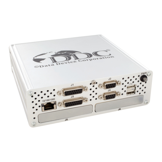
Page 16: Figure 2. Bu-67121Wx Avionics Interface Computer
O V E R V I E W Front view Rear view Figure 2. BU-67121Wx Avionics Interface Computer Data Device Corporation BU-67121W Manual www.ddc-web.com Rev B – 6/16... -
Page 17: Power Adaptor
Electronics CENB1080A2403F01 100/240 VAC-to-24 VDC (3.25 Amp) power adaptor. This comes with separate line cords for operation in the US, UK, Europe, and Japan. The power adaptor is included with every model of the AIC. Data Device Corporation BU-67121W Manual www.ddc-web.com Rev B – 6/16... -
Page 18: Specifications
• Frequency Using Direct DC Power Input • Input Voltage - Steady state range 22.8 25.2 ENVIROMENTAL CHARACTERISTICS THERMAL Operating Temperature BU-67121W (ambient temperature, includes internal fan) °C Non-Operating Temperature BU-67121W °C HUMIDITY Operating Humidity (non-condensing) BU-67121W Non-Operating Humidity (non-condensing) - Page 19 O V E R V I E W Table 1. BU-67121Wx Specification Table PARAMETER UNITS Size • BU-67121W 6.69 x 6.91 x 2.10 169.9 x 175.5 x 53.3 Weight • BU-67121WM03-JL0 43.5 (1233) oz. (g) Data Device Corporation BU-67121W Manual www.ddc-web.com...
-
Page 20: Modes And Operation
STD-1553 and/or ARINC 429 channels. In the remote access configuration, the user is able to write applications running on a remote host that invoke the AceXtreme MIL- STD-1553 and/or ARINC 429 APIs. For use in Remote Access Mode, DDC offers Data Device Corporation BU-67121W Manual www.ddc-web.com... -
Page 21: Figure 5. Example Of Avionics Interface Computer Used In Remote Access Mode
3.2.1 Optional Software Tools – BusTrACEr, dataSIMS, etc. For the Remote Access Mode, as an alternative to developing application software, the user may operate the AIC using any of DDC’s GUI software programs. These include: • BusTrACEr. The BU-69066S0-XX0 BusTrACEr allows a user to generate and monitor MIL-STD-1553 messages. -
Page 22: Protocol Conversion Mode
To minimize setup time and provide more “turnkey” operation, the AIU includes a high-level protocol conversion API. Alternatively, users may develop their own protocol conversion applications invoking DDC’s AceXtreme MIL-STD-1553 and/or ARINC 429 APIs, along with the Linux socket interfaces for the Ethernet channel. -
Page 23: Start Up
START UP See the BU-69094SX-002 Software manual. Data Device Corporation BU-67121W Manual www.ddc-web.com Rev B – 6/16... -
Page 24: Detailed Architecture
If using DDC cards, additional details for the ARINC 429 and MIL-STD-1553 portions can be found in the hardware manuals for the cards installed in the AIC. The DDC card’s manuals can be found on the DDC website at www.ddc-web.com. -
Page 25: Hardware Installation
The type of screws used on case of the AIC are Torx type screws Size 10. There are five screws on the front of the AIC. The four corners and one in the top- middle. See Figure 7 below. Data Device Corporation BU-67121W Manual www.ddc-web.com Rev B – 6/16... -
Page 26: Figure 7. Front Panel Screws
Note: Before proceeding to slide out the main board, please disconnect the rear fan plug from the board. Failing to do so, may damage your AIC. See Figure 9 and Figure 10 Disconnecting Fan Plug below. Data Device Corporation BU-67121W Manual www.ddc-web.com Rev B – 6/16... -
Page 27: Figure 9. Disconnecting Fan Plug
H A R D W A R E I N S T A L L A T I O N Figure 9. Disconnecting Fan Plug Figure 10. Disconnecting Fan Plug con’t Now you can freely slide out the main board to access the various slots on board. Data Device Corporation BU-67121W Manual www.ddc-web.com Rev B – 6/16... -
Page 28: Aic Main Board
Figure 12 and Figure 13 depict the AIC main board, top and bottom. The onboard connectors and card slots are numbered. Refer to Table 2 and Table 3. to see what the numbers correspond to. Data Device Corporation BU-67121W Manual www.ddc-web.com Rev B – 6/16... -
Page 29: Figure 12. Aic Mainboard - Top View
8a. 20 pin Onboard header to route Mini PCI-e slot A 15. VGA port signals to J1 and J2. 8b. 24 pin Onboard header to route Mini PCI-e slot A 16. Serial port signals to J1 and J2. Data Device Corporation BU-67121W Manual www.ddc-web.com Rev B – 6/16... -
Page 30: Aic Mini Pci-E Sites
Also in Figure 12, labels 10a & 10b represent the onboard headers that the signals from cards in slot B will be routed to the front panel D-Sub connectors, J3 & J4. Data Device Corporation BU-67121W Manual www.ddc-web.com Rev B – 6/16... -
Page 31: Figure 14. Mini Pci-E Headers Pcb Labels
Figure 14. Mini PCI-e headers PCB labels 6.4.1 Installing a Mini PCI-e card To install a Mini PCI-e card. Slide the card in to the desired slot. Use the included screws to secure the card. Data Device Corporation BU-67121W Manual www.ddc-web.com Rev B – 6/16... -
Page 32: Figure 15. 20-Pin Ffc
H A R D W A R E I N S T A L L A T I O N 6.4.1.1 For installing a DDC card Included with your AIC are a set of Flat Flex Cables to interface your DDC cards with the front panel connectors.. -
Page 33: Figure 16. 24-Pin Ffc
6.4.1.2 For installing a 3 party card In order to utilize the front panel connectors of the AIC with your Mini PCI-e card, you will have to create/purchase a FPC flex cable. Data Device Corporation BU-67121W Manual www.ddc-web.com Rev B – 6/16... -
Page 34: Aic Pmc Sites
‘Pn’ connectors. This is because the AIC will have the standoffs installed on the motherboard in those spots. See Figure 17. Removing PMC card standoffs, and Figure 18. Pre-installed spacers on AIC motherboard. Data Device Corporation BU-67121W Manual www.ddc-web.com Rev B – 6/16... - Page 35 H A R D W A R E I N S T A L L A T I O N Figure 17. Removing PMC card standoffs. Data Device Corporation BU-67121W Manual www.ddc-web.com Rev B – 6/16...
- Page 36 Please see Warning Note! above. To secure the PMC card a user will have to screw in screws on each side of the AIC motherboard. See Figure 20. and Figure 21. Data Device Corporation BU-67121W Manual www.ddc-web.com Rev B – 6/16...
- Page 37 H A R D W A R E I N S T A L L A T I O N Cheese head Screw M2.5 x 6 Figure 20. Rear positioned PMC screws. This is on the bottom side of the motherboard. Data Device Corporation BU-67121W Manual www.ddc-web.com Rev B – 6/16...
- Page 38 Once the user screws the PMC card down it should be safe, secure and ready for operation. When using DDC PMC cards, The user may want to install a jumper on to the correct jumper block so that the firmware will be able to be flashed in case a problem or update arises.
-
Page 39: Software Installation
69094SX Protocol Conversion SDK Software User’s Manual. Updating The Flash Firmware These firmware sections are associated with DDC devices only. Updating the firmware on the AIC can be done in a couple of ways. It can be done through the web server via browser or it can be done by logging into the device itself using telnet or utilizing the VGA port with a monitor and using Standalone Mode. -
Page 40: Figure 17. Telnet Login
A pwd command will display the path where you currently are in the AIC. This path and the firmware file name will be needed to flash the firmware on a card installed in the AIC. Data Device Corporation BU-67121W Manual www.ddc-web.com Rev B – 6/16... -
Page 41: Figure 19. Location Path For Firmware Files
S O F T W A R E I N S T A L L A T I O N Figure 24. Location path for firmware files You can launch ddccm, the DDC card manager application at any point, and in any directory to view your installed devices and have the ability to update the firmware. -
Page 42: Figure 21. Selection Of The Device To Be Flashed
After selecting the device to be flashed you will be prompted to “Enter the filename to program”. This is where you need that path and filename from Figure and Figure . See Figure 23 below. Data Device Corporation BU-67121W Manual www.ddc-web.com Rev B – 6/16... -
Page 43: Figure 22. Entering The Firmware Path And Name To Start Flashing
After entering the correct path and filename and hitting enter, you will see the device and file attributes. It will also ask you to confirm if you want to flash the device or not. Figure 24. Confirming to flash the firmware Data Device Corporation BU-67121W Manual www.ddc-web.com Rev B – 6/16... -
Page 44: Figure 24. Flash Process Started, Erasing Flash Sectors
Sector” with a certain number of sectors. Once that portion has completed, the prompts will start to say “Programming” and a percentage with hex addresses will be displayed. Figure 25. Flash process started, Erasing Flash Sectors Data Device Corporation BU-67121W Manual www.ddc-web.com Rev B – 6/16... -
Page 45: Figure 25. Programming New Firmware
This will bring up a prompt and ask you for credentials to access the AIC’s web page. Log in using your credentials. Default Credentials: Username: ddc Password: ddc Upon entering the web page, you will see a menu on the left hand side. Choose Device Information. Data Device Corporation BU-67121W Manual www.ddc-web.com Rev B – 6/16... -
Page 46: Figure 26. Aic Web Page Device Information
PCI-e card is installed and can be re-flashed. Click on Choose File, and a window will pop up where you will need to navigate to the correct location and choose the correct firmware file. Data Device Corporation BU-67121W Manual www.ddc-web.com Rev B – 6/16... -
Page 47: Figure 27. Locate Firmware File Window
Once you choose the correct firmware file, you can click Update Firmware. Your browser will update and display a prompt for you to confirm you want to flash the device. Data Device Corporation BU-67121W Manual www.ddc-web.com Rev B – 6/16... -
Page 48: Figure 28. Browser Page Updated To Ask For Confirmation
Figure 33. Browser page updated to ask for confirmation Once you have selected Yes, you will then jump to the Flash Status menu where you will see the progress of your flashing process. Figure 34. Erasing flash sectors Data Device Corporation BU-67121W Manual www.ddc-web.com Rev B – 6/16... -
Page 49: Figure 30. Programming Firmware
Hitting refresh will cause the browser to reload the last known saved form data. In this case the form data would be the firmware .bin file. This will cause the device to restart the flash programming again Data Device Corporation BU-67121W Manual www.ddc-web.com Rev B – 6/16... -
Page 50: Connectors And Pinouts
J5 and J6 will have a closed bezel (as pictured in Figure .) until user chooses to install PMC cards. The user can unscrew the bezels exposing a slot for a front I/O PMC card to interface with. Figure 36. BU-67121WX Front Panel Connectors Data Device Corporation BU-67121W Manual www.ddc-web.com Rev B – 6/16... -
Page 51: Figure 32. Bu-67121Wx Rear Panel Connectors
J5 and J6 will beopen PMC slots. If you choose to populate the slots with DDC PMC cards, then you will be able to use the cables that are provided with those cards . Please refer to those device’s hardware manual for additional connector information. -
Page 52: Signal Lists
Table 6. AIC Signal List J1 – J4 & Ethernet, USB, VGA, RS-232 Signal Name Description J1 through J4 signals will depend on which cards are installed. If using DDC cards, then please refer to the individual card’s manual for signal lists. Ethernet Signals E1 TXRX 1+ Ethernet Tx/Rx 1 Signal (Positive) - Page 53 Serial Transmit Data Signal Ground Signals RGND Red Ground GGND Green Ground BGND Blue Ground SGND Sync Ground Ground Reference DGND Digital Ground CHASSIS GND No Connect. Do NOT Connect. Data Device Corporation BU-67121W Manual www.ddc-web.com Rev B – 6/16...
-
Page 54: Connector Pinouts
C O N N E C T O R S A N D P I N O U T S 8.2.2 J5 Signal List J5 will be an open PMC slot. If using a DDC card, please refer to the card’s manual for the signal list. -
Page 55: Figure 34. Aic J2 9-Pin D-Sub Connector
8.3.2 AIC J2 Connector Figure 39. AIC J2 9-Pin D-Sub Connector When populating the Mini PCI-e site A with DDC cards, the following table shows which signals come out of each pin on the connector. Table 8. J2 9-Pin D-Sub Connector Pinout... -
Page 56: Table 9. Aic D-Subs To 20-Pin Onboard Header Pin Out
8.3.3 Mini PCI-e Site A with non-DDC Card J1 and J2 can be used with a non-DDC mini PCI-e card. The user will have to create their own cable to connect from their card to the onboard header to route the signals to the front connectors. -
Page 57: Table 10. Aic D-Subs To 24-Pin Onboard Header Pin Out
Table 9. AIC D-Subs to 20-pin onboard header pin out Table 10. AIC D-Subs to 24-pin onboard header pin out AIC J1 9-Pin D-Sub 24-pin header (J14 on PCB) AIC J2 15-Pin D-Sub 24-pin header (J14 on PCB) Data Device Corporation BU-67121W Manual www.ddc-web.com Rev B – 6/16... -
Page 58: Figure 35. Aic J3 15-Pin D-Sub Connector
429 Mini PCI-e Site B CHASSIS GND CH1A_717/429_RX_TX_IO CH1_TX_INH CH1B_717/429_RX_TX_IO CH1_BC_DISABLE CH2A_717/429_RX_TX_IO CH1_EXT_TRIG_SS_FLAG# CH2B_717/429_RX_TX_IO IRIG_DIG CH3A_429_RX_TX_IO CH2_TX_INH CH3B_429_RX_TX_IO CH2_BC_DISABLE CH4A_429_RX_TX_IO CH2_EXT_TRIG_SS_FLAG# CH4B_429_RX_TX_IO DGND DGND CH5A_429_RX_ONLY_IO CH5B_429_RX_ONLY_IO CH6A_429_RX_ONLY_IO CH6B_429_RX_ONLY_IO DIGITAL_IRIG_IN SPARE (CHASSIS GND) Data Device Corporation BU-67121W Manual www.ddc-web.com Rev B – 6/16... -
Page 59: Figure 36. Aic J4 9-Pin D-Sub Connector
8.3.6 Mini PCI-e Site B with non-DDC card J3 and J4 can be used with a non-DDC mini PCI-e card. The user will have to create their own cable to connect from their card to the onboard header to route the signals to the front connectors. -
Page 60: Table 14. Aic D-Subs To 24-Pin Onboard Header Pin Out
20-pin header (J18 on PCB) Table 14. AIC D-Subs to 24-pin onboard header pin out AIC J3 9-Pin D-Sub 24-pin header (J17 on PCB) AIC J4 15-Pin D-Sub 24-pin header (J17 on PCB) Data Device Corporation BU-67121W Manual www.ddc-web.com Rev B – 6/16... -
Page 61: Figure 37. Female Rj-45 Jack For Ethernet
AIC. The card’s manual will have the details for the connectors. 8.3.8 10/100/1000 BASE-T Ethernet Port The AIC will have one RJ-45 jack on the front panel for Ethernet connectivity. Figure 42. Female RJ-45 jack for Ethernet Data Device Corporation BU-67121W Manual www.ddc-web.com Rev B – 6/16... -
Page 62: Figure 38. Usb 2.0 Type A Receptacle
BU-67121Wx VBUS 8.3.10 VGA Video Connector The AIC will have a VGA connector for use with connecting a monitor. The connector is located on the back panel of the AIC. Data Device Corporation BU-67121W Manual www.ddc-web.com Rev B – 6/16... -
Page 63: Figure 39. 15-Pin Vga Video Connector
BU-67121Wx Green Blue RGND GGND BGND SGND HSync VSync 8.3.11 RS-232 Serial Communication Conenctor The AIC will include a Male 9-Pin D-Sub connector on the rear panel for serial communication. Data Device Corporation BU-67121W Manual www.ddc-web.com Rev B – 6/16... -
Page 64: Mating Connectors
The BU-67121WX is supplied with various mating connectors and backshells for front connectors, along with a 100/240 VAC-to-24 VDC power adaptor. The mating connectors, and power adaptor that are provided with the AIC are shown in Table 19. Data Device Corporation BU-67121W Manual www.ddc-web.com Rev B – 6/16... -
Page 65: Figure 41. Aic J1 Mating Connector
15-pin, Male, ‘D’ connector (NorComp 171-015-102L001). The backshell for the connector is an Amphenol 17E-1657-15. The pinout for AIC J1 is shown in Table 7. Figure 46. AIC J1 Mating Connector Data Device Corporation BU-67121W Manual www.ddc-web.com Rev B – 6/16... -
Page 66: Figure 42. Aic J2 Mating Connector
Male, ‘D’ connector (NorComp 171-015-102L001). The backshell for the connector is an Amphenol 17E-1657-15. The pinout for AIC J3 is shown in Table 11. Figure 48. AIC J3 Mating Connector Data Device Corporation BU-67121W Manual www.ddc-web.com Rev B – 6/16... -
Page 67: External Power Supply
• For the UK: Qualtek 370001-E01 (2.5 meters = 98.4 in.) • For Europe: Qualtek 3640002-D01 (2.5 meters = 98.4 in.) • For Japan: Qualtek 397002-01 (2.5 meters = 98.4 in.) Data Device Corporation BU-67121W Manual www.ddc-web.com Rev B – 6/16... -
Page 68: Ordering Information
2GB DDR3L SDRAM, 30 53 mm) GByte SSD Notes: 1. Contact the Factory for more ordering options. 2. Product Specifications for DDC’s PMC and Mini-PCIe boards are available at www.ddc-web.com/databus Included Accessories: For the BU-67121WX model Mating Connector to AIC J1: ... - Page 69 SL Power Electronics CENB1080A2403F01 • Comes with the following AC Line cords: o Qualtek 212004-01 (US) o Qualtek 370001-E01 (UK) o Qualtek 3640002-D01 (Europe) Qualtek 397002-01 (Japan) BU-69094R OS Restoration flash drive Data Device Corporation BU-67121W Manual www.ddc-web.com Rev B – 6/16...
- Page 70 Data Bus | Synchro/Resolver Digital Conversion| Power Controllers | Motor Controllers DDC is a leader in the development, design, and manufacture of highly reliable and innovative military data bus solutions. DDC's Data Networking Solutions include MIL-STD-1553, ARINC 429, Ethernet and Fibre Channel.
- Page 71 FILE NO. 10001296 ASH09 The first choice for more than 50 years—DDC France: DDC Electronique DDC is the world leader in the design and manufacture of high reliability 84-88 Bd de la Mission Marchland data interface products, motion control, and solid-state power controllers 92411 Courbevoie Cedex, France for aerospace, defense, and industrial automation.