Table of Contents
Advertisement
Quick Links
Notice
The information in this guide is subject to change without notice.
Compaq Computer Corporation shall not be liable for technical or editorial
errors or omissions contained herein; nor for incidental or consequential
damages resulting from the furnishing, performance, or use of this
material.
This guide contains information protected by copyright. No part of this
guide may be photocopied or reproduced in any form without prior written
consent from Compaq Computer Corporation.
Copyright 1994 Compaq Computer Corporation.
All rights reserved. Printed in the U.S.A.
Compaq, Deskpro, LTE, Contura
Registered U.S. Patent and Trademark Office.
LTE Elite, SmartStation, and MiniStation are trademarks of Compaq Computer
Corporation.
Microsoft and MS-DOS are registered trademarks of Microsoft Corporation.
Windows is a trademark of Microsoft Corporation.
The software described in this guide is furnished under a license agreement
or nondisclosure agreement. The software may be used or copied only in
accordance with the terms of the agreement.
Product names mentioned herein may be trademarks and/or registered
trademarks of their respective companies.
MAINTENANCE AND SERVICE GUIDE
COMPAQ LTE ELITE FAMILY OF PERSONAL COMPUTERS
COMPAQ SMARTSTATION
First Edition (March 1994)
Part Number 194061-001
Advertisement
Table of Contents
Troubleshooting

Related Manuals for Compaq LTE Elite


Summary of Contents for Compaq LTE Elite
- Page 1 All rights reserved. Printed in the U.S.A. Compaq, Deskpro, LTE, Contura Registered U.S. Patent and Trademark Office. LTE Elite, SmartStation, and MiniStation are trademarks of Compaq Computer Corporation. Microsoft and MS-DOS are registered trademarks of Microsoft Corporation. Windows is a trademark of Microsoft Corporation.
- Page 2 USING THIS GUIDE This Maintenance And Service Guide is a troubleshooting reference for servicing the Compaq LTE Elite Family of Personal Computers, the Compaq SmartStation, the Compaq MiniStation/EN, and the Compaq MiniStation/TR. The guide is organized into the following parts:...
- Page 3 >>>>>>>>>>>>>>>>>>>>>>>>>>>>>>>>>>>>><<<<<<<<<<<<<<<<<<<<<<<<<<<<<<<<<<<<<< LOCATING ADDITIONAL INFORMATION The following documentation is available to support the Compaq LTE Elite Family of Personal Computers and its options. o Documentation included with the computer: - Online USER'S GUIDE...
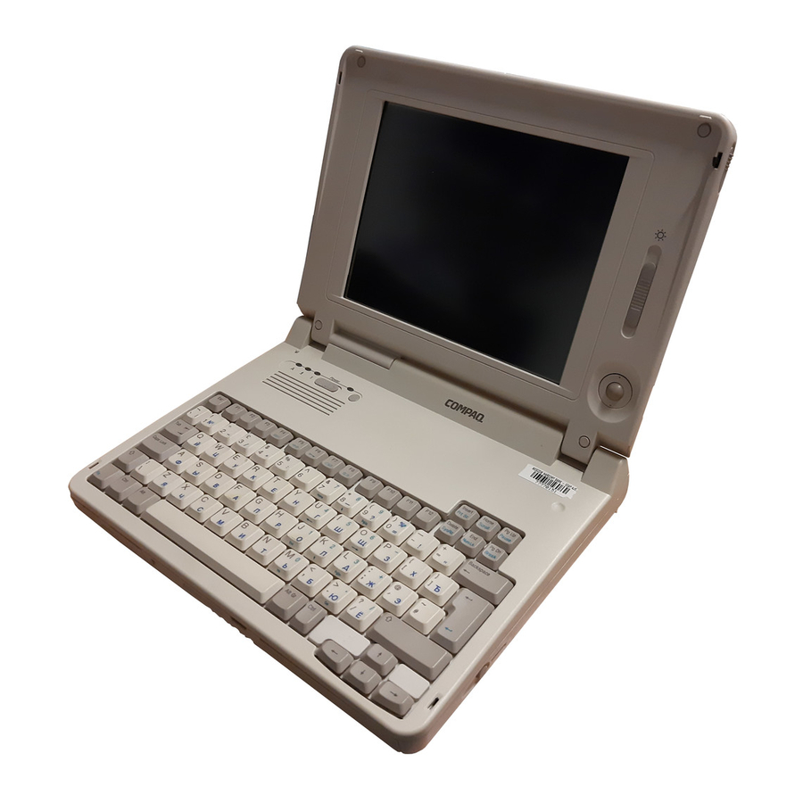
- Page 4 Chapter 1 - Compaq LTE Elite Product Overview Introduction This chapter is an overview of the Compaq LTE Elite Family of Personal Computers and covers the following topics: o Serial number o System overview o Models and features o Controls and LEDs...
-
Page 5: System Overview
Processor board o RAM memory expansion board The Compaq LTE Elite is designed to dock in one of the following options: o Compaq SmartStation (Figure 1-1) o Compaq LTE Lite Desktop Expansion base (with a Compaq LTE Lite Upgrade... - Page 6 Computer power is supplied through one of the following sources: o An internal battery pack o The computer's internal AC adapter when connected to the power cord (Figure 1-2) o The computer's internal AC adapter when docked in a convenience base o The 198-pin external options connector when docked in an expansion base (provides DC power) o Automobile Adapter (provides DC power)
- Page 7 1.3 Models And Features Models Table 1-1 lists the Compaq LTE Elite models and model-specific features. Table 1-1. Compaq LTE Elite Computer Models =========================================================================== Model Display =========================================================================== 4/75CX 9.5" Color TFT 4/50CX 9.5" Color TFT 4/40CX 8.4" Color TFT 4/50E 9.5"...
- Page 8 o Internal AC adapter o Upgradeable SL Enhanced Intel486 microprocessors o User upgradeable display with integrated trackball o Local bus graphics and graphics accelerator with 1024 x 768 external video support o Simultaneous display capability o Removable 2.5-inch hard drive o Reprogrammable flash ROM (Section 1.9) o 4 MB system RAM expandable to 20 MBs or 8 MB system RAM expandable to 24 MBs.
-
Page 9: Controls And Leds
o The following preinstalled software: - MS-DOS and Microsoft Windows - TabWorks utility (alternative to Program Manager) - Computer Setup, Computer Checkup, Power Management, and Security Management utilities - Automatic PCMCIA configuration utilities for MS-DOS and Windows - Windows-based online documentation - Plug and Play BIOS - MS-DOS- and Windows-based shutdown capability (for closing out applications and turning off computer) - Page 10 1. Caps lock LED 2. Display switch 3. Scroll lock LED 4. Num lock LED 5. Power switch 6. Standby button 7. Power/standby LED 8. Hard drive LED 9. Diskette drive LED 10. Power/standby LED 11. Battery LED 12. Trackball 13.
- Page 11 Power/ Power on standby Flashing Standby --------------------------------------------------------------------------- Battery Battery State charging Flashing LowBatt 1 at one second Flashing LowBatt 2 at two second --------------------------------------------------------------------------- Hard Drive Hard drive Activity being accessed --------------------------------------------------------------------------- Diskette Diskette Drive drive being Activity accessed --------------------------------------------------------------------------- Scroll Scroll lock Lock...
- Page 12 1. AC power 2. Automobile Adapter 3. Serial 4. 198-pin external options 5. Keyboard/mouse 6. Parallel 7. External monitor 8. Numeric keypad 9. PCMCIA AC Power Connector When the computer is docked in the convenience base and the convenience base is turned on, AC power is applied to the computer's AC power connector.
- Page 13 NOTE: The automobile adapter converts 12 volts DC from the automobile to 18.5 volts DC for use by the computer. >>>>>>>>>>>>>>>>>>>>>>>>>>>>>>>>> CAUTION <<<<<<<<<<<<<<<<<<<<<<<<<<<<<<<<< The computer has an access door for the automobile adapter connector that is designed to allow only one type of power input (AC or DC) to be connected at a time (Figure 1-5).
- Page 14 Keyboard/Mouse Connector The keyboard/mouse connector can be connected to a PS/2 mouse or an external enhanced keyboard. Connecting the mouse/keyboard connector to a mouse disables the integrated trackball, while connecting the mouse/keyboard connector to an external keyboard disables the internal keyboard. Parallel Connector The parallel connector supports the parallel interface which meets EPP 1.9 specifications.
- Page 15 The system board (Figure 1-6) provides the following: o Connector for removable hard drive [1] o PCMCIA connector [2] (refer to "PCMCIA Slot") o Board-to-board connection to the following devices: - Power interface board (PIB) [3] - Processor board [4] - Memory expansion board (on underside of system board) o Cable connection to the following devices: - Internal AC power supply board [5]...
- Page 16 o Battery charging circuitry and battery contacts [10] for battery pack o External input/output (I/O) connectors (Figure 1-4) o DC-to-DC power supply (refer to "DC-to-DC Power Supply" in this section) o 256 Kbyte flashable shared system ROM and keyboard ROM o 4 or 8 MB base RAM (depending on the model) o System controller, which provides the following: - Interface to the processor board for memory management (including...
- Page 17 voltage input comes from one of the following sources: o Internal AC power supply o Battery pack o Automobile adapter o 198-pin external options connector (from expansion base) o Auxiliary battery To replace the DC-to-DC power supply, the system board must be replaced. Processor Board The SL Enhanced Intel486 processor has an integrated coprocessor and is upgradeable by replacing the processor board (Figure 1-7).
- Page 18 NOTE: The 75 MHz processor is also available as an upgrade option. Temperature Sensors The primary temperature sensor is located on the processor board and the secondary temperature sensor is located on the system board. These sensors turn the fan on when the system approaches maximum reliable operating temperatures.
- Page 19 o Numeric keypad connector o Speaker and speaker amplifier o Power switch o Standby button o Display switch o The following LEDs: - Power/standby - Scroll lock - Caps lock - Num lock Refer to Section 1.4 for more information on the controls and LEDs listed above.
- Page 20 Personal Computers (option kit numbers 144790-001 and 144790-002) operate at 80 ns and do not function properly when installed in the Compaq LTE Elite Family of Personal Computers, which operate at 70 ns. Use only Compaq LTE Elite memory expansion boards (Table 3-2).
- Page 21 The internal fan (Figure 1-11) draws in fresh air through vent holes in the PCMCIA compartment door, then exhausts it out the back of the computer. The fan operates on 5 volts and is controlled by temperature sensors located near the internal power supply and the processor board. The fan is designed to turn on automatically when the system approaches maximum reliable operating temperatures (refer to "Temperature Sensors"...
- Page 22 The removable internal nickel metal hydride (NiMH) battery pack connects to the computer through a set of battery contacts mounted on the system board. Battery charging functions are controlled by the DC-to-DC converter on the system board. The battery pack contains RAM memory that saves the last recorded battery operating time and battery fuel gauge values.
- Page 23 memory for a one-minute period during Standby to allow a battery pack to be replaced. The auxiliary battery has a nickel cadmium cell that supplies 7.2 volts for 50 mAmp hours. The auxiliary battery recharges when the computer is on while connected to an external power source or the battery pack.
- Page 24 NOTE: The Compaq Diagnostics utilities (which include Computer Setup) reside in a hidden partition on the Compaq LTE Elite hard drive (not in the ROM). There is no preinstalled software on a new spare hard drive.
- Page 25 is already created and the diagnostics utilities are already installed. IMPORTANT: The hard drive must be handled with care. listed in Section 4.12. Display Assembly The display assembly (Figure 1-14) is connected to the system unit by clutches, a display cable and a ground cable. The display assembly includes an integrated trackball board and an inverter board.
- Page 26 Refer to Section 5.4 for display specifications. NOTE: A certain number of pixels in the display panel are allowed to be nonfunctional due to limitations in LCD technology. PCMCIA Slot The PCMCIA connector is mounted to the system board. The connector is accessible through the PCMCIA slot [1], (Figure 1-15), which is covered by a PCMCIA compartment door.
-
Page 27: Running Computer Setup
Call Compaq Reseller Support to have a copy of the list faxed to you. 1.7 Docking Options The Compaq LTE Elite docks with the following options (Figure 1-16): o Compaq SmartStation expansion base o Compaq LTE Lite Desktop Expansion Base (with an Upgrade Adapter) o Compaq MiniStation/EN and MiniStation/TR convenience bases Refer to Appendix D for more information on docking and undocking. -
Page 28: Power Management
Run Computer Setup for the following situations: o To configure options o To update alarm, time, date, or password information NOTE: Alarm, time, and date information can be lost if the computer is unused for approximately 60 days without charging the internal battery pack or without AC power being connected (refer to "Auxiliary Battery"... - Page 29 and when the system is idle. This function is transparent to the user. APM also provides occasional screen messages about the battery while in the Windows environment (for example, low power condition). Power Management Settings You can select power conservation settings through Computer Setup, Power Management, or by pressing the Fn + F7 hotkeys to maximize power for specific requirements.
- Page 30 Standby is a power conservation mode for battery or AC power operation during which most of the components (e.g, hard drive, processor, display) shut down. The computer initiates Standby under the following conditions: o When the user presses the standby button [1] (Figure 1-17). o After a timeout occurs.
- Page 31 Hibernation Hibernation is a power conservation mode that performs the following functions: o Locks the keyboard and clears the screen. o Saves all current information in memory and the place in the application to the hard drive. o Turns the computer off. Hibernation is preenabled on the computer and the Hibernation file is preinstalled on the hard drive.
- Page 32 1.11 Security The computer has the following security features: o Power-on password and setup password. o The ability to disable certain components, such as the keyboard, diskette drive, display, PCMCIA slot, parallel connector, and serial connector, to prevent unauthorized access. o Provision for an optional cable lock (Figure 1-18) to lock the computer to an immovable object.
-
Page 33: Preliminary Steps
Chapter 2 - Compaq LTE Elite Troubleshooting Introduction This chapter covers troubleshooting information for the computer. The basic steps in troubleshooting include: 1. Following the preliminary steps listed in Section 2.1. 2. Running the Power-On Self-Test (POST) as described in Section 2.2. - Page 34 5. Disconnect any external devices that you do not want to test. (Do not disconnect the printer if you want to test it or use it to log error messages.) NOTE: If a problem only occurs when an external device is connected to the computer, the problem may be with the external device or its cable.
- Page 35 password-clearing position [2]). Refer to Figure 2-1. 6. Move the jumper from the normal "1-2" position [1] to the "2-3" position [2] (Figure 2-1). 7. Insert the battery pack. IMPORTANT: Ensure that the battery pack is charged since a low battery condition could initiate Standby and interrupt the procedure.
- Page 36 12. Insert the battery pack. 13. Turn on the computer to verify that the power-on password has been cleared. If it has not been cleared, remove the battery pack and then repeat steps 6 through 13. If the password is still not cleared, replace the system board (Section 4.17).
- Page 37 If POST does not detect any errors, the computer beeps once or twice to indicate that POST has run successfully and starts (boots) from the hard drive (or from a bootable diskette if one is installed in the diskette drive). If POST detects errors, the errors are indicated by screen and/or audible messages.
- Page 38 Increase Detected ------------------------------------------------ 164 - Memory 2 Short Decrease Detected --------------------------------------------------------------------------- 168 - CMOS None Checksum Invalid --------------------------------------------------------------------------- ** Autosetup configures to the default settings if you do not run Computer Setup. =========================================================================== Message Beeps =========================================================================== 201 - Memory None Error --------------------------------------------------------------------------- 203 - Memory...
- Page 39 --------------------------------------------------------------------------- 205 - Memory None Error --------------------------------------------------------------------------- 207 - Invalid None Memory Configuration Module --------------------------------------------------------------------------- 209 - NCA RAM None Error --------------------------------------------------------------------------- 211 - Memory None Failure --------------------------------------------------------------------------- 301 - Keyboard None Error 301 - Keyboard None Error or Text Fixture Installed ===========================================================================...
- Page 40 --------------------------------------------------------------------------- 602 - Diskette None Boot --------------------------------------------------------------------------- 605 - Diskette 2 Short Drive Error --------------------------------------------------------------------------- 610 - External None storage device failure. =========================================================================== Message Beeps =========================================================================== 611 - Primary 2 Short Floppy Port Address Assignment Conflict --------------------------------------------------------------------------- 612 - Secondary 2 Short Floppy Port Address...
- Page 41 Failure --------------------------------------------------------------------------- 1150 - COM Port Configuration Error --------------------------------------------------------------------------- 1151 - COM Port 2 Short 1 Address Assignment Conflict --------------------------------------------------------------------------- 1152 - COM Port 2 Short 2 Address Assignment Conflict --------------------------------------------------------------------------- 1771 - Primary 2 Short Disk Port Address Assignment Conflict =========================================================================== Message...
- Page 42 --------------------------------------------------------------------------- 1793 - Secondary None Disk Controller or Disk Failure --------------------------------------------------------------------------- Audible 1 Short --------------------------------------------------------------------------- Audible 2 Short --------------------------------------------------------------------------- (RESUME = F1 None KEY) =========================================================================== 2.3 Computer Checkup (Test) After POST runs successfully, run the latest version of Computer Checkup (TEST).
- Page 43 The Configuration and Diagnostics menu is displayed. 4. Select Computer Checkup (TEST) from the Configuration and Diagnostics menu. The Computer Checkup options menu is displayed. 5. Select View Device List. A list of the installed hardware devices is displayed. NOTE: Computer Checkup may not detect non-Compaq devices. 6.
- Page 44 12. Rerun POST and Computer Checkup, completing the recommended actions in the order given until the problem is solved and no error messages occur. Computer Checkup (TEST) Error Codes Computer Checkup (TEST) error codes occur if the system recognizes a problem while running Computer Checkup.
- Page 45 failed. --------------------------------------------------------------------------- 112 - xx Speed test slow mode out of range. --------------------------------------------------------------------------- 113 - 01 Protected mode test failed. --------------------------------------------------------------------------- 114 - 01 Speaker test failed. --------------------------------------------------------------------------- 116 - xx Cache test failed. =========================================================================== Table 2-3. Memory Computer Checkup Error Codes =========================================================================== Error Code Description...
- Page 46 8042 self-test failed. --------------------------------------------------------------------------- 302 - xx Keyboard long test failed. --------------------------------------------------------------------------- 303 - xx Keyboard LED test, 8042 self-test failed. --------------------------------------------------------------------------- 304 - xx Keyboard typematic test failed. =========================================================================== Table 2-5. Parallel Printer Computer Checkup Error Codes =========================================================================== Error Code Description =========================================================================== 401 - xx...
- Page 47 604 - xx Diskette random seek test failed. 605 - xx Diskette ID media failed. 606 - xx Diskette speed test failed. 607 - xx Diskette wrap test failed. 608 - xx Diskette write protect test failed. 609 - xx Diskette reset controller test failed.
- Page 48 Table 2-9. Hard Drive Computer Checkup Error Codes =========================================================================== Error Code Description =========================================================================== 1700 - xx Hard ID drive types test failed. 1701 - xx Hard drive format test failed. 1702 - xx Hard drive read test failed. 1703 - xx Hard drive write/read/compare test failed.
- Page 49 Table 2-10. Tape Drive Computer Checkup Error Codes =========================================================================== Error Code Description =========================================================================== 1900 - xx Tape ID failed. 1901 - xx Tape servo write failed. 1902 - xx Tape format failed. 1903 - xx Tape drive sensor test failed. 1904 - xx Tape BOT/EOT test failed.
- Page 50 test failed. 2416 - xx Video noise pattern test failed. 2417 - xx Light pen text mode test failed, no response. 2418 - xx ECG/VGC memory test failed. 2419 - xx ECG/VGC ROM checksum test failed. 2421 - xx ECG/VGC 640 x 200 graphics mode test failed.
- Page 51 2478 - xx Advanced VGA BitBLT test. 2480 - xx Advanced VGA Linedraw test. =========================================================================== Table 2-12. Audio Computer Checkup Error Codes =========================================================================== Error Code Description =========================================================================== 3206 - xx Audio system internal error. =========================================================================== Table 2-13. Network Controller Computer Checkup Error Codes =========================================================================== Error Code Description...
- Page 52 6002 - xx Network card transmit failed. =========================================================================== Error Code Description =========================================================================== 6014 - xx Ethernet configuration test failed. 6016 - xx Ethernet reset test failed. --------------------------------------------------------------------------- 6028 - xx Ethernet internal loopback test failed. 6029 - xx Ethernet external loopback test failed.
- Page 53 =========================================================================== Error Code Description =========================================================================== 6054 - xx Token Ring configuration test failed. 6056 - xx Token Ring reset test failed. --------------------------------------------------------------------------- 6068 - xx Token Ring internal loopback test failed. --------------------------------------------------------------------------- 6069 - xx Token Ring external loopback test failed. --------------------------------------------------------------------------- 6089 - xx Token Ring open.
- Page 54 For example, with error code 6523-05, the first two-digit number of the error code (65) indicates a disk problem (Table 2-14A). The second two-digit number (23) indicates a random read (Table 2-14B). The last two-digit number (05) indicates a seek failure (Table 2-14C). Thus, in this example, the diagnostics program tested the random read functioning of the hard drive and received a seek failure.
- Page 55 --------------------------------------------------------------------------- xxxx - 18 No data detected. --------------------------------------------------------------------------- xxxx - 21 Drive command aborted. --------------------------------------------------------------------------- 65xx - 24 Media hard error. --------------------------------------------------------------------------- 66xx - 24 Media hard error. --------------------------------------------------------------------------- 67xx - 24 Media hard error. =========================================================================== Error Code Description =========================================================================== xxxx - 30 Controller timed out.
- Page 56 --------------------------------------------------------------------------- xxxx - 54 BSY stayed busy. --------------------------------------------------------------------------- xxxx - 60 Controller CONFIG-1 register bad. --------------------------------------------------------------------------- xxxx - 61 Controller CONFIG-2 register bad. =========================================================================== Table 2-15. Pointing Device Interface Computer Checkup Error Codes =========================================================================== Error Code Description =========================================================================== 8601 - xx Pointing Device Interface test failed ===========================================================================...
- Page 57 the computer malfunction against the problem description in the troubleshooting tables to avoid a misdiagnosis. >>>>>>>>>>>>>>>>>>>>>>>>>>>>>>>>> WARNING <<<<<<<<<<<<<<<<<<<<<<<<<<<<<<<<< To avoid a potential shock hazard during troubleshooting procedures, disconnect all power sources before removing the keyboard cover or the display bezel. >>>>>>>>>>>>>>>>>>>>>>>>>>>>>>>>>>>>><<<<<<<<<<<<<<<<<<<<<<<<<<<<<<<<<<<<<<...
- Page 58 ------------------------------------------------------- Battery pack was exposed to temperature extremes. ------------------------------------------------------- Battery pack is at end of its life. ------------------------------------------------------- Battery contacts not making good contact with battery pack. ------------------------------------------------------- Defective system board. =========================================================================== Problem Probable Cause =========================================================================== Computer shut Battery pack was not down and data replaced within one was lost when...
- Page 59 Battery charge Power conservation is does not last as disabled or set to long as expected. "None." ------------------------------------------------------- An external device or PCMCIA card is draining the battery. --------------------------------------------------------------------------- Battery pack is Normal warming has warm to the touch occurred due to after charging.
- Page 60 Table 2-18. Diskette/Diskette Drive Problems =========================================================================== Problem Probable Cause =========================================================================== Diskette drive Diskette is damaged. LED stays on. ------------------------------------------------------- Software program is damaged. --------------------------------------------------------------------------- Diskette drive Diskette is write- cannot write to a protected. diskette. ------------------------------------------------------- Computer is writing to the wrong drive.
- Page 61 incorrect. --------------------------------------------------------------------------- Screen is blank. QuickBlank is initiated. ------------------------------------------------------- Another screen blanking utility may be installed. ------------------------------------------------------- Screen save was initiated by Power Management due to lack of user activity. ------------------------------------------------------- If a color STN is used, brightness/contrast control slide needs adjusting.
- Page 62 --------------------------------------------------------------------------- Internal display Display function was is blank and the switched to the external screen on an monitor. external monitor displays information. --------------------------------------------------------------------------- Distorted or The ANSI.SYS driver is garbled not in the CONFIG.SYS characters on the file or the path is display are mixed incorrect.
- Page 63 --------------------------------------------------------------------------- The light tubes Display switch is stuck on the edge of in the off position. the display panel light up momentarily when unit is powered up, but turn off during or after POST. Power LED lights up on front of unit but not on top.
- Page 64 Improper display cable connections. ------------------------------------------------------- Defective inverter board. ------------------------------------------------------- Defective display cable. ------------------------------------------------------- Defective display panel. =========================================================================== Problem Probable Cause =========================================================================== The display panel Improper display cable has a continuous connections. pattern across it (e.g., a "jailbars" pattern), has a single color on it, or has garbled graphics...
- Page 65 ------------------------------------------------------- Defective power interface board. ------------------------------------------------------- Defective system board. --------------------------------------------------------------------------- * On the color STN models, brightness is adjusted with the control slide on the right, and contrast is adjusted with the control slide on the left. ** When using an external monitor and simultaneously displaying an image on the internal display, the image on the external monitor may not fill the screen.
- Page 66 Problem Probable Cause =========================================================================== A new device is Computer Setup has not not recognized as been run to configure part of the the new device. computer system. ------------------------------------------------------- Cable(s) of new external device are loose or power cables are unplugged. ------------------------------------------------------- Power switch of new external device was not...
- Page 67 keypad on turned on. computer keyboard is disabled. --------------------------------------------------------------------------- Embedded numeric External numeric keypad keypad is is connected to the disabled and Num computer. Lock function is --------------------------------------------------------------------------- External keyboard External keyboard is not does not work. securely connected or is connected to an incorrect external connector.
- Page 68 NOTE: Files on the diskette are not needed to use the Compaq LTE Lite with a network adapter or the Compaq LTE Elite with the built-in Ethernet controller in the Compaq SmartStation. Refer to the correct version of Service Advisory 737 for a comprehensive...
- Page 69 Table 2-24. Network Problems =========================================================================== Problem Probable Cause =========================================================================== Computer Setup The computer is not does not detect docked in the expansion the network base. interface. ------------------------------------------------------- There is a conflict between the network interface and an optional device installed on the computer or the expansion base.
- Page 70 ------------------------------------------------------- The files for the network drivers have been corrupted. --------------------------------------------------------------------------- When using the A software patch is Compaq LTE Elite, required. the network adapter drivers cannot be loaded, the network application has slow performance, or the network...
- Page 71 ------------------------------------------------------- The PCMCIA slot is disabled. ------------------------------------------------------- Card or card driver is not PCMCIA compliant. =========================================================================== Problem Probable Cause =========================================================================== The PCMCIA The PCMCIA slot is drivers (Socket disabled. Services, Card Services, Card ID) fail with error messages when the computer is turned on.
- Page 72 PCMCIA network Network driver is not card does not set up properly. work. =========================================================================== Problem Probable Cause =========================================================================== Storage card does SRAM and flash memory not work. cards require the memory card driver to be loaded. ------------------------------------------------------- Flash memory cards require the Microsoft FlashFile System to be loaded.
- Page 73 =========================================================================== Computer is Computer has entered a beeping and low battery condition. battery LED is flashing. --------------------------------------------------------------------------- Computer turned The unit temperature was off. exceeded. ** ------------------------------------------------------- Fan may be blocked, causing temperature to exceed limits. ** --------------------------------------------------------------------------- Computer turned System initiated off while left Hibernation according to...
- Page 74 ------------------------------------------------------- Defective system board. --------------------------------------------------------------------------- Unit powers up Faulty AC power cord. from the battery pack, but not from AC power. ------------------------------------------------------- Faulty cable connection from internal power supply. ------------------------------------------------------- Defective internal AC power supply. --------------------------------------------------------------------------- The computer has Power switch not no power at all functioning.
- Page 75 seconds.) --------------------------------------------------------------------------- * For information on solving battery problems, refer to Table 2-16. ** The fan turns on and off automatically when the computer reaches certain temperatures. This is normal. =========================================================================== Table 2-27. Printer Problems * part. In addition, note that the first three parts can be checked by the user.
- Page 76 =========================================================================== Problem Probable Cause =========================================================================== Printer does not The device drivers for print. the application are not installed. ------------------------------------------------------- Printer that is set up for a network is not connected to the network. ------------------------------------------------------- Printer cable is too long, unshielded, or defective.
- Page 77 Memory configuration is not set up correctly. ------------------------------------------------------- System ran out of memory for the application. --------------------------------------------------------------------------- * TSRs (Terminate Stay Resident) are software routines that stay in RAM memory even when not actively in use. =========================================================================== Table 2-29. Sound Problems =========================================================================== Problem Probable Cause...
- Page 78 Table 2-32. Trackball/Mouse Problems =========================================================================== Problem Cause =========================================================================== Trackball or Incorrect or no device mouse does not driver is installed. work. ------------------------------------------------------- The device driver is not installed in Windows. --------------------------------------------------------------------------- Internal An external pointing trackball does device is connected to not work.
- Page 79 ------------------------------------------------------- Bottom of trackball board is shorting to display shield. ------------------------------------------------------- Display cable not properly seated in trackball board. ------------------------------------------------------- Display cable is torn, causing intermittent open circuit. ------------------------------------------------------- Defective trackball board. =========================================================================== 2.5 Contacting Compaq Reseller Support Obtain the following information before contacting Compaq Reseller Support: o Product name o Product serial number (Section 1.1) o Purchase date...
- Page 80 IMPORTANT: Ensure that there is no diskette in the diskette drive and that there are no PCMCIA cards in the PCMCIA slot. 4. Close the display and all exterior doors (external options, PCMCIA compartment, memory, and hard drive). 5. Pack the computer with sufficient packing material to protect it. Use the original packing box or similar packaging.
- Page 81 Introduction This chapter provides illustrated parts breakdowns and identifies the spare parts for the Compaq LTE Elite Family of Personal Computers, including the Compaq MiniStation/EN and the Compaq MiniStation/TR. Refer to Chapter 8 for spare part information for the Compaq SmartStation.
- Page 82 --------------------------------------------------------------------------- 3. Base Enclosure Includes the following installed parts: - Battery pack release latch assembly (button, latch, and spring) - Hard drive release latch assembly (button, latch, and spring) - PCMCIA compartment door and spring - Automobile adapter door - Hard drive compartment door =========================================================================== 3.2 Boards Table 3-2.
- Page 83 3. Internal AC Power Supply (includes right hinge cover) 4. System Board: - 4 MB - 8 MB 5. Memory Expansion Board (70 ns): - 4 MB - 8 MB - 16 MB 6. LED Cable Assembly 7. Trackball Board (includes trackball) 8.
- Page 84 Table 3-3. Display - Model-Specific Display Parts =========================================================================== =========================================================================== 1. Display Bezel 9.5 Inch Color TFT 8.4 Inch TFT 9.5 Inch Black and White TFT 9.5 Inch Color STN 10.4 Inch Color TFT 3. Display Panel 9.5 Inch Color TFT 8.4 Inch Color TFT 9.5 Inch Black and White TFT 9.5 Inch Color STN...
- Page 85 5. Display Cable 9.5 Inch Color TFT 8.4 Inch Color TFT 9.5 Inch Black and White TFT 9.5 Inch Color STN 10.4 Inch Color TFT 8. Display Ground Cable 9.5 Inch Color TFT 8.4 Inch Color TFT 9.5 Inch Black and White TFT 9.5 Inch Color STN 10.4 Inch Color TFT 9.
- Page 86 3.4 Mass Storage Devices Table 3-4. Mass Storage Devices =========================================================================== Description =========================================================================== 1. 3.5-inch, 1.44 MB Diskette Drive 2. Diskette Drive Cable 3. Removable Hard Drive - 810 MB - 510 MB - 340 MB - 250 MB - 170 MB 4.
- Page 87 Table 3-5. Batteries =========================================================================== Description =========================================================================== 1. NiMH Battery Pack 2. Auxiliary Battery =========================================================================== 3.6 Cables And Connectors Spare Part Number 149599-001 149598-001...
- Page 88 Table 3-6. Cables and Connectors =========================================================================== Description =========================================================================== 1. PCMCIA Ejector Rails (includes PCMCIA spacer tool) 2. LED Cable Assembly 3. Diskette Drive Cable 4. Power Cord - U.S./Canadian - European - U.K. - Japanese - Australian 5. ZIF Connector Slides 6.
- Page 89 =========================================================================== 3.7 Keyboards Table 3-7. Keyboards =========================================================================== Description =========================================================================== U.S. English U.K. English German French Italian Spanish Danish Norwegian Swedish/Finnish Swiss French Canadian Portuguese Latin American Belgian Japanese Spare Part Number 149608-001 149608-003 * 149608-004 * 149608-005 * 149608-006 * 149608-007 * 149608-008 * 149608-009 *...
-
Page 90: Miscellaneous Plastics Kit
--------------------------------------------------------------------------- * Not shown. =========================================================================== 3.8 Latches Kit Table3-8. Latches Kit =========================================================================== Description =========================================================================== Kit includes: Battery release latch assembly (button, latch, and spring) Hard drive release latch assembly (button, latch, and spring) Right display latch, latch spring, and button Left display latch, latch spring, and button =========================================================================== 3.9 Doors Kit... - Page 91 Table3-12a. Compaq LTE Elite Screws and Fasteners Kit =========================================================================== Description =========================================================================== Compaq LTE Elite Screws and Fasteners Kit (Quantity = 25) =========================================================================== Table 3-12b. Compaq LTE Elite Screw and Fastener Locations =========================================================================== Where Used Description =========================================================================== DISPLAY ENCLOSURE AND BOARDS: Bezel to...
- Page 92 SYSTEM UNIT BOARDS/CONNECTORS: Internal AC Screw, power supply M2.5 x 6.0 to system board (on top) --------------------------------------------------------------------------- Internal AC Screw, power supply M2.5 x 6.0 to system unit enclosure (at rear) =========================================================================== Where Used Description =========================================================================== Serial, Screwlock, parallel, 4-40 sems, external ext.
- Page 93 SYSTEM UNIT ENCLOSURE: Keyboard Screw, cover to M2.5 x 21.0 system unit enclosure (on bottom) --------------------------------------------------------------------------- Keyboard Screw, cover to M2.5 x 6.0 system unit enclosure (at rear) --------------------------------------------------------------------------- Clutches to Screw, system unit M2.5 x 10.0 enclosure =========================================================================== 3.13 Tools Table 3-13.
- Page 94 4. Display Bezel Removal Tool 5. Loopback Plugs * --------------------------------------------------------------------------- * Not shown. =========================================================================== 3.14 Options Table 3-14. Compaq LTE Elite Options and Accessories =========================================================================== Description =========================================================================== 1. Compaq LTE Lite Desktop Expansion Base Upgrade Kit ** (includes Network Install...
- Page 95 Spare Part Number column. ** Compaq LTE Lite Desktop Expansion Base Upgrade Kit modifies a desktop expansion base to allow a Compaq LTE Elite to dock with it. The upgrade kit is a user-installed option. *** Not shown.
- Page 96 >>>>>>>>>>>>>>>>>>>>>>>>>>>>>>>>> WARNING <<<<<<<<<<<<<<<<<<<<<<<<<<<<<<<<< To avoid the risk of electric shock, the I/O bracket overlay must be installed on the I/O bracket of the Compaq MiniStation. >>>>>>>>>>>>>>>>>>>>>>>>>>>>>>>>>>>>><<<<<<<<<<<<<<<<<<<<<<<<<<<<<<<<<<<<<< Table 3-15. Compaq MiniStation Convenience Bases =========================================================================== Description =========================================================================== 1. Monitor Support Cover --------------------------------------------------------------------------- 2.
- Page 97 Portables ROMPaq Upgrade Diskette Supplemental Programs Diskette (includes EXTDISK) [English] Video Software Kit =========================================================================== 3.17 Documentation Table3-17. Documentation =========================================================================== Description =========================================================================== Compaq LTE Elite/Compaq SmartStation Maintenance and Service Guide --------------------------------------------------------------------------- Online User's Guide: English German 195566-001 196782-001 195567-001 198861-001 195565-001 *...
- Page 98 Authorized Compaq Reseller Version End User Version --------------------------------------------------------------------------- Compaq EZ-SCSI Software Reference English German French =========================================================================== 3.18 Shipping Box Table3-18. Shipping Box =========================================================================== Description =========================================================================== Compaq LTE Elite Shipping Box =========================================================================== 194641-051 194641-061 194641-071 194641-101 194641-331 149709-001 149709-041 149709-051 149709-061 149709-071 149709-081...
-
Page 99: Replacement Procedures
Replacement Procedures Introduction This chapter provides subassembly level removal and replacement procedures for the Compaq LTE Elite. Unless otherwise specified, the steps for replacement procedures are the reverse of the steps for the removal procedures. After completing all necessary removal and replacement procedures, run POST and Computer Setup to verify that all components operate properly (refer to Chapter 2). - Page 100 o Keyboard to system board o Diskette drive to system board o Display cable to system board o Display cable to display panel (black-and-white TFT only) To remove a cable from a ZIF connector, lift both corners of the ZIF connector slide simultaneously with constant light force until the connector slide releases, then remove the cable (Figure 4-1).
-
Page 101: Required Tools And Software
Screws >>>>>>>>>>>>>>>>>>>>>>>>>>>>>>>>> CAUTION <<<<<<<<<<<<<<<<<<<<<<<<<<<<<<<<< Screws in the unit are not interchangeable. Damage may occur if you insert an incorrect screw. As you remove screws, place them with the component you removed to help avoid error. >>>>>>>>>>>>>>>>>>>>>>>>>>>>>>>>>>>>><<<<<<<<<<<<<<<<<<<<<<<<<<<<<<<<<<<<<< Plastics Use care when handling the plastic case and housing assemblies, as they can be damaged from excessive force during assembly and disassembly. - Page 102 - Display cable - Display latches - Display clutches - Display enclosure 4.10 Keyboard 4.11 Diskette drive and cable 4.12 Hard drive - Hard drive security clips 4.13 Processor board 4.14 Power interface board (PIB) 4.15 PCMCIA ejector rails 4.16 Internal AC power supply 4.17 System board and I/O bracket 4.18 LED cable assembly 4.19 Computer base enclosure...
-
Page 103: Battery Pack
Place only the battery pack for the Compaq LTE Elite Family of Personal Computers into the battery compartment. The Compaq LTE Elite battery pack and the battery compartment are keyed to allow only a correct insertion. -
Page 104: Memory Expansion Board
Replacing the Battery Pack To replace the battery pack, complete the following steps: 1. Insert the battery pack with the large label facing up and the battery contacts facing the inside of the battery compartment. 2. Push firmly on the battery pack. When released, it locks into place. - Page 105 Removing the Memory Expansion Board Before removing the memory expansion board, refer to Section 4.4, "Preparation Procedures for Removal and Replacement." To remove the memory expansion board, complete the following steps: 1. Turn the unit display-side down. 2. Release the latch on the memory access cover (Figure 4-3). 3.
- Page 106 Installing the Memory Expansion Board To install the memory expansion board, complete the following steps: >>>>>>>>>>>>>>>>>>>>>>>>>>>>>>>>> CAUTION <<<<<<<<<<<<<<<<<<<<<<<<<<<<<<<<< The two connectors on the memory expansion board are similar in appearance, but they are keyed so you can only insert them in the proper manner. To avoid damage to the system board or the memory expansion board, be sure that you are aligning the correct connectors.
-
Page 107: Keyboard Cover
4.7 Keyboard Cover Before removing the keyboard cover, refer to Section 4.4, "Preparation Procedures for Removal and Replacement." To remove the keyboard cover, complete the following steps: 1. Turn the unit display-side down. 2. Remove the five screws located on the bottom and the one screw (shorter than the other five) located near the external options connector on the rear panel (Figure 4-5). - Page 108 3. Carefully holding the unit together, turn it right-side up. 4. Open the display to its fully open position. 5. Tilt up the back edge of the keyboard cover [1] and lift while rotating the cover toward you to release the front edge [2] (Figure 4-6).
- Page 109 IMPORTANT: When replacing the keyboard cover, angle the front edge of the keyboard cover into place at the front of the computer, ensuring that the tabs on the keyboard cover correctly align with the corresponding recesses on the computer. Gently press the rear edge of the keyboard cover into place at the back of the computer, and verify that the front edge is aligned.
-
Page 110: Display Assembly
remove the auxiliary battery connector. >>>>>>>>>>>>>>>>>>>>>>>>>>>>>>>>>>>>><<<<<<<<<<<<<<<<<<<<<<<<<<<<<<<<<<<<<< 2. Using a non-metallic tool such as the connector removal tool (Table 3-13), slightly press the auxiliary battery connector toward the internal power supply to release the retentive force on the connector [1] (Figure 4-7). 3. - Page 111 parts compatibility, the spare display panel, inverter board, display cable, and display enclosure for the 9.5-inch color TFT model come preinstalled in the display assembly. To replace these parts, replace the entire display assembly (color TFT model only). If required, the trackball board may be replaced separately on the color TFT model.
- Page 112 IMPORTANT: When replacing the cable into the ZIF connector, fully seat the cable before closing the ZIF connector slide. Close the connector slide by simultaneously pressing on both corners. When closed, the insertion line on the cable should be even with the top edge of the connector slide.
- Page 113 IMPORTANT: When replacing the display ground cable, ensure that it is fully seated to prevent it from disconnecting from the ground clip. 5. Remove the four screws that attach the display clutches to the computer (Figure 4-10). >>>>>>>>>>>>>>>>>>>>>>>>>>>>>>>>> CAUTION <<<<<<<<<<<<<<<<<<<<<<<<<<<<<<<<< To avoid damaging the display assembly, handle it carefully.
- Page 114 IMPORTANT: When replacing the display assembly, close the display and check to ensure that the display latches align properly. If the latches require a realignment, loosen (do not remove) the four display clutch screws, align the latches, then reseat the screws.
- Page 115 1. Remove the display control slide(s) by lifting up on one of its ends (Figure 4-11). NOTE: The color STN display has two control slides (brightness and contrast), while all other displays have only one control slide (brightness). >>>>>>>>>>>>>>>>>>>>>>>>>>>>>>>>> CAUTION <<<<<<<<<<<<<<<<<<<<<<<<<<<<<<<<< To prevent damage to the inverter board when replacing the display control slide(s), fully snap the bezel back into place before you replace the slide(s).
- Page 116 (Figure 4-12) and continue unsnapping towards the bottom edge until the bezel and enclosure are completely separated. NOTE: A display bezel removal tool (Table 3-13) may be used to assist in removing the display bezel. Display Panel NOTE: To replace the display panel on the 9.5-inch color TFT model, replace the entire display assembly (refer to "Removing the Display Assembly"...
- Page 117 >>>>>>>>>>>>>>>>>>>>>>>>>>>>>>>>> CAUTION <<<<<<<<<<<<<<<<<<<<<<<<<<<<<<<<< To avoid damaging the display panel, do not remove any Phillips screws on the display panel. These screws hold the display panel together. There are no serviceable parts located inside the display panel. >>>>>>>>>>>>>>>>>>>>>>>>>>>>>>>>>>>>><<<<<<<<<<<<<<<<<<<<<<<<<<<<<<<<<<<<<< 3. Remove the four T-8 screws that attach the display panel to the display enclosure (Figure 4-14).
- Page 118 IMPORTANT: When replacing the display panel, replace (but do not tighten) the display panel screws and position the panel as far to the right of the display enclosure as the screws allow before tightening them. function properly to ensure proper display brightness. In addition, ensure that one of the mounting tabs of the display ground cable is connected beneath the display panel and is attached by the lower-left display panel screw.
- Page 119 >>>>>>>>>>>>>>>>>>>>>>>>>>>>>>>>> CAUTION <<<<<<<<<<<<<<<<<<<<<<<<<<<<<<<<< The display cable and ZIF connector on the black-and-white TFT display panel can be easily damaged. Handle only the connector slide when removing or replacing the cable; never pull or twist on the cable while it is connected.
- Page 120 IMPORTANT: When replacing the cable into the ZIF connector on the black-and-white TFT display panel, fully seat the cable before closing the ZIF connector slide. Close the connector slide by simultaneously pressing on both corners. When closed, the insertion line on the cable should be even with the top edge of the connector slide.
- Page 121 NOTE: To replace the inverter board on the 9.5-inch color TFT model, replace the entire display assembly (refer to "Removing the Display Assembly" in this section). It is not necessary to remove the display assembly from the system unit to remove the display inverter board.
- Page 122 >>>>>>>>>>>>>>>>>>>>>>>>>>>>>>>>> CAUTION <<<<<<<<<<<<<<<<<<<<<<<<<<<<<<<<< To avoid damage to the trackball cable when replacing the inverter board, be sure that the inverter board screws do not come in contact with the trackball cable. >>>>>>>>>>>>>>>>>>>>>>>>>>>>>>>>>>>>><<<<<<<<<<<<<<<<<<<<<<<<<<<<<<<<<<<<<< Trackball Board It is not necessary to remove the display assembly to remove the trackball board.
- Page 123 Display Cable NOTE: To replace the display cable on the 9.5-inch color TFT model, replace the entire display assembly (refer to "Removing the Display Assembly" in this section). It is not necessary to remove the display assembly to remove the display cable.
- Page 124 7. Remove the display cable. NOTE: Figure 4-19 shows an exploded view of the display cable connections. Display Latches IMPORTANT: The display latches and latch buttons used on the display enclosure are labeled L (left) and R (right) and are not interchangeable.
- Page 125 3. Remove the display latches and springs from the latch compartments. Display Clutches To remove the display clutches, complete the following steps: 1. Remove the keyboard cover (Section 4.7). 2. Remove the display assembly (refer to "Removing the Display Assembly" in this section).
- Page 126 the factory. the original trackball shield is reused, the tab for the trackball shield must go back in its original position (above or beneath the clutch). When replacing the trackball shield with a new spare trackball shield (Table 3-11), the mounting tab always goes beneath the clutch.
- Page 127 3. Remove the display bezel (refer to "Display Bezel" in this section). 4. Remove the display panel (refer to "Display Panel" in this section). 5. Remove the display inverter board (refer to "Inverter Board" in this section). 6. Remove the trackball board (refer to "Trackball Board" in this section).
- Page 128 >>>>>>>>>>>>>>>>>>>>>>>>>>>>>>>>>>>>><<<<<<<<<<<<<<<<<<<<<<<<<<<<<<<<<<<<<< 3. Gently slide the keyboard toward the display to release its front edge from the computer (Figure 4-22). 4. Slightly lift up the keyboard [1] to access the keyboard cable (Figure 4-23). >>>>>>>>>>>>>>>>>>>>>>>>>>>>>>>>> CAUTION <<<<<<<<<<<<<<<<<<<<<<<<<<<<<<<<< The keyboard cable and ZIF connector on the system board can be easily damaged.
- Page 129 Replacing the Keyboard To replace the keyboard, complete the following steps: >>>>>>>>>>>>>>>>>>>>>>>>>>>>>>>>> CAUTION <<<<<<<<<<<<<<<<<<<<<<<<<<<<<<<<< The keyboard cable and ZIF connector on the system board can be easily damaged. Handle only the connector slide when replacing the cable; never pull or twist on the cable while it is connected. >>>>>>>>>>>>>>>>>>>>>>>>>>>>>>>>>>>>><<<<<<<<<<<<<<<<<<<<<<<<<<<<<<<<<<<<<<...
- Page 130 front edge of the computer (Figure 4-24). IMPORTANT: To ensure that the keyboard is reinstalled correctly, be sure that the metal tabs on the keyboard's front edge are properly aligned (Figure 4-24). The two tabs on the outside [1] go in the notches on top of the plastic edge at the front of the computer.
- Page 131 centered on the drive so that it does not protrude over the plastic ribs of the battery bay or the hard drive bay and interfere with reassembly. >>>>>>>>>>>>>>>>>>>>>>>>>>>>>>>>> CAUTION <<<<<<<<<<<<<<<<<<<<<<<<<<<<<<<<< To avoid damage to the drive, handle the drive by the sides. Do not handle the drive by the top or bottom, since the drive enclosure is designed primarily as a shield.
-
Page 132: Hard Drive
7. If required, remove the cable from the diskette drive. >>>>>>>>>>>>>>>>>>>>>>>>>>>>>>>>> CAUTION <<<<<<<<<<<<<<<<<<<<<<<<<<<<<<<<< To avoid damage to the diskette drive, do not remove the drive from its metal enclosure. >>>>>>>>>>>>>>>>>>>>>>>>>>>>>>>>>>>>><<<<<<<<<<<<<<<<<<<<<<<<<<<<<<<<<<<<<< 4.12 Hard Drive Removing the Hard Drive The hard drive in the computer is removable from the front without requiring disassembly. - Page 133 o Remove and replace the hard drive only when the computer is OFF, unplugged, and the battery pack is removed. Do not remove or replace a hard drive while the computer is ON, in Standby, or in Hibernation. To determine whether the computer is in Hibernation, complete the following steps: a.
- Page 134 NOTE: The hard drive may have either a metal handle (Figure 4-27) or a plastic pull tab that is attached directly to the hard drive enclosure. >>>>>>>>>>>>>>>>>>>>>>>>>>>>>>>>> CAUTION <<<<<<<<<<<<<<<<<<<<<<<<<<<<<<<<< To avoid damage to the hard drive or the computer, do not pull on the hard drive handle or pull tab unless you first press and hold down the hard drive release button.
- Page 135 Replacing the Hard Drive The Compaq Diagnostics utilities (which include Computer Setup) on the Compaq LTE Elite reside in a hidden partition on the hard drive (not in the ROM). There is no preinstalled software on a new spare hard drive. When...
- Page 136 Installing the Compaq Diagnostics Utilities on a New Hard Drive To create the hidden partition, install the diagnostics utilities, and format the drive, complete the following steps: 1. Place the Compaq Diagnostics diskette into drive A. 2. Turn on the computer. 3.
- Page 137 To remove the hard drive security clips, complete the following steps: 1. Remove the keyboard cover (Section 4-7). 2. Reinsert the battery pack halfway into the battery compartment [1] so that the battery pack does not touch the battery contacts on the system board (Figure 4-29).
- Page 138 4. Remove the two remaining screws on the keyboard [1] (Figure 4-30). >>>>>>>>>>>>>>>>>>>>>>>>>>>>>>>>> CAUTION <<<<<<<<<<<<<<<<<<<<<<<<<<<<<<<<< To avoid damage to the keyboard, be careful when handling it, since the keyboard cable is still connected. Do not pull on the cable. >>>>>>>>>>>>>>>>>>>>>>>>>>>>>>>>>>>>><<<<<<<<<<<<<<<<<<<<<<<<<<<<<<<<<<<<<< 5.
- Page 139 6. Rotate the front edge of the keyboard up and lay it face-down on the cloth-covered display panel (Figure 4-31).
- Page 140 7. Remove the hard drive security clips by gently lifting up on them (Figure 4-32).
-
Page 141: Processor Board
IMPORTANT: When replacing the hard drive security clips, position each clip over the notches in the plastic rib near the front of the hard drive enclosure. Insert each clip until the top surface of the clip is flush with the top surface of the plastic rib. - Page 142 >>>>>>>>>>>>>>>>>>>>>>>>>>>>>>>>> CAUTION <<<<<<<<<<<<<<<<<<<<<<<<<<<<<<<<< Electrostatic discharge (ESD) can damage electronic components. Ensure that you are properly grounded before beginning these procedures. >>>>>>>>>>>>>>>>>>>>>>>>>>>>>>>>>>>>><<<<<<<<<<<<<<<<<<<<<<<<<<<<<<<<<<<<<< Removing the Processor Board To remove the processor board, complete the following steps: 1. Remove the keyboard cover (Section 4.7). >>>>>>>>>>>>>>>>>>>>>>>>>>>>>>>>>...
- Page 143 Replacing the Processor Board To replace the processor board, complete the following steps: 1. Position the processor board over the connectors on the system board, ensuring that it is aligned correctly (Figure 4-34). >>>>>>>>>>>>>>>>>>>>>>>>>>>>>>>>> CAUTION <<<<<<<<<<<<<<<<<<<<<<<<<<<<<<<<< The two connectors on the processor board are similar in appearance, but they are keyed so that you can only insert them in the proper manner.
- Page 144 4.14 Power Interface Board (PIB) To remove the power interface board (PIB), complete the following steps: 1. Remove the keyboard cover (Section 4.7). 2. Remove the three PIB screws [1] [2] and the display switch spring [3], which is secured by the back left PIB screw (Figure 4-35). IMPORTANT: When replacing the PIB, be sure to align the display switch spring in its alignment hole before replacing the back left screw.
- Page 145 >>>>>>>>>>>>>>>>>>>>>>>>>>>>>>>>>>>>><<<<<<<<<<<<<<<<<<<<<<<<<<<<<<<<<<<<<< >>>>>>>>>>>>>>>>>>>>>>>>>>>>>>>>> CAUTION <<<<<<<<<<<<<<<<<<<<<<<<<<<<<<<<< To avoid damage to the connector pins on the system board, disconnect the PIB only from the right side, since that is the side located directly over the connector. Do not lift the PIB from the left side. When replacing the PIB, be sure to line up the connector pins, as they can be easily misaligned and damaged.
- Page 146 removing or replacing the ejector rails. Removing the PCMCIA Ejector Rails To remove the PCMCIA ejector rails, complete the following steps: 1. Remove the keyboard cover (Section 4.7). 2. Remove the PIB, PIB insulator, and PIB shield (Section 4.14). 3. Remove the top ejector rail by sliding it gently but firmly out of the system unit (Figure 4-37).
- Page 147 mounting screws. To replace the PCMCIA ejector rails, complete the following steps: 1. Slide the bottom ejector rail into position until it locks into place (Figure 4-38). 2. Slide the top ejector rail into position until it locks into place (Figure 4-38).
- Page 148 4. Replace the PIB, PIB insulator, and PIB shield (Section 4.14). NOTE: After installing the screws for the PIB, the PCMCIA spacer can be removed or left in the PCMCIA slot for storage. 5. Replace the keyboard cover (Section 4.7). 4.16 Internal AC Power Supply NOTE:The DC-to-DC power supply is integrated into the system board.
- Page 149 Do not disassemble the internal power supply, as there are no field serviceable parts inside. >>>>>>>>>>>>>>>>>>>>>>>>>>>>>>>>>>>>><<<<<<<<<<<<<<<<<<<<<<<<<<<<<<<<<<<<<< To remove the internal AC power supply, complete the following steps: 1. Remove the keyboard cover (Section 4.7). 2. Remove the hinge cover from the top of the internal AC power supply by sliding it toward the front of the unit (Figure 4-40).
- Page 150 4. Remove the two screws that attach the power supply to the rear of the system unit (Figure 4-42). NOTE: To allow the screws to align easier when replacing the power supply, replace the two rear screws before replacing the two top screws.
- Page 151 >>>>>>>>>>>>>>>>>>>>>>>>>>>>>>>>> CAUTION <<<<<<<<<<<<<<<<<<<<<<<<<<<<<<<<< To avoid damage to the internal AC power supply, be careful when lifting up on it, since the cable is still attached. Do not attempt to fully remove the internal AC power supply until the cable is disconnected. >>>>>>>>>>>>>>>>>>>>>>>>>>>>>>>>>>>>><<<<<<<<<<<<<<<<<<<<<<<<<<<<<<<<<<<<<<...
- Page 152 4.17 System Board And Input/Output (I/O) Bracket To remove the system board and input/output bracket, complete the following steps: 1. If a new system board is to be installed, remove the memory expansion board (Section 4.6). 2. Remove the hard drive (Section 4.12). 3.
- Page 153 8. Remove the diskette drive and cable (Section 4.11). 9. Remove the PIB (Section 4.14). 10. Remove the internal AC power supply (Section 4.16). 11. Remove the eight screwlocks that attach the rear I/O connectors to the I/O bracket (Figure 4-44). 12.
- Page 154 interferes with the installation of the system board. >>>>>>>>>>>>>>>>>>>>>>>>>>>>>>>>> CAUTION <<<<<<<<<<<<<<<<<<<<<<<<<<<<<<<<< To avoid a potential short to the computer, do not use a metal tool to remove the fan connector. >>>>>>>>>>>>>>>>>>>>>>>>>>>>>>>>>>>>><<<<<<<<<<<<<<<<<<<<<<<<<<<<<<<<<<<<<< 14. Using a non-metallic tool such as the connector removal tool (Table 3-13), slightly press down against the top of the fan connector [1] to release the retentive force on the connector (Figure 4-46).
- Page 155 16. Remove the six screws that attach the system board to the computer base enclosure (Figure 4-47). IMPORTANT: To ensure proper alignment when replacing the system board, replace the screw noted as [1], then replace the screw noted as [2], then replace the other four screws (Figure 4-47).
- Page 156 17. Carefully tilt the system board up [1] and unplug the LED cable assembly from the connector on the bottom side of the system board [2] (Figure 4-48).
- Page 157 IMPORTANT: When replacing the LED cable assembly into the connector, be sure that the soldered leads on the cable face away from the system board. 18. With the system board still tilted up, slide the system board toward the front of the unit to release it from the I/O bracket, and remove the system board.
-
Page 158: Led Cable Assembly
NOTE: The fan is integrated into the I/O bracket. To replace the fan, the I/O bracket must be replaced. 4.18 LED Cable Assembly Removing the LED Cable Assembly To remove the LED cable assembly from the computer base enclosure, complete the following steps: 1. - Page 159 Replacing the LED Cable Assembly To replace the LED cable assembly, complete the following steps: 1. Connect the LED cable assembly [1] to its connector on the system board [2] (Figure 4-51). IMPORTANT: Be sure that the soldered leads on the LED cable face away from the system board.
- Page 160 2. Partially install the system board so that the connectors on the back of the board fit into the I/O bracket. Keep the front edge of the system board raised to allow access to the LED cable assembly bracket (Figure 4-52).
- Page 161 3. Insert the lower edge of the LED cable assembly [1] into the lower slot of the LED cable assembly bracket (Figure 4-53). 4. Rotate the top edge of the LED cable assembly up and press gently at the top corners [2] (Figure 4-53) to snap it into the bracket. IMPORTANT: Both sides of the LED cable assembly must be pressed simultaneously to allow the assembly to snap into the bracket.
- Page 162 5. Reassemble the rest of the computer by reversing steps 1 through 16 of Section 4.17. 4.19 Computer Base Enclosure To remove the computer base enclosure, complete the following steps: 1. Remove the system board and I/O bracket (Section 4.17). 2.
- Page 163 NOTE: The I/O connector cover, Automobile Adapter door, and hard drive compartment door are available in the Doors Kit (Table 3-9). 4.20 PCMCIA Compartment Door The PCMCIA compartment door comes installed on the computer base enclosure. The door and spring are also available separately in the Doors Kit (Table 3-9).
- Page 164 Replacing the PCMCIA Compartment Door To replace the PCMCIA compartment door, complete the following steps: 1. Position the door spring [1] over its retaining post [2] on the computer base enclosure (Figure 4-55). 2. Position the long end of the spring [3] into its slot on top of the computer base enclosure (Figure 4-55) so that it stays in place.
- Page 165 3. With the door held in the fully open position, install the back hinge of the door [1] onto its post on the computer base enclosure (Figure 4-56). 4. Slightly flexing the door, replace the front hinge of the door [2] onto its post on the computer base enclosure (Figure 4-56).
- Page 166 4.21 Battery Pack/Hard Drive Release Latch Assemblies This section covers removal and replacement procedures for the battery pack release latch assembly and the hard drive release latch assembly. Each assembly includes the following: o Release button o Latch o E-clip o Latch spring The release buttons, latches, and latch springs work together as assemblies to release the battery pack and hard drive.
- Page 167 Removing the Release Latch Assembly To remove either the battery pack or hard drive release latch assembly, complete the following steps: 1. If you are removing the hard drive release latch assembly, remove the hard drive (Section 4.12). 2. Remove the keyboard cover (Section 4.7). 3.
- Page 168 Replacing the Release Latch Assembly IMPORTANT: The parts for the battery release latch and hard drive release latch assemblies are similar in appearance. However, note that the battery latch is color-coded white, and the hard drive latch is color-coded black. for this procedure.
- Page 169 attached to the enclosure. Leave the existing latch spring installed unless it is defective. >>>>>>>>>>>>>>>>>>>>>>>>>>>>>>>>>>>>><<<<<<<<<<<<<<<<<<<<<<<<<<<<<<<<<<<<<< 3. Replace the e-clip [3] over the latch (Figure 4-58). 4. To replace the latch spring, gently slide the spring [4] down into its slot while placing its free end [5] over the triangular-shaped ledge of the latch (Figure 4-58).
- Page 170 Chapter 5 - Compaq LTE Elite Specifications Introduction This chapter covers the following specifications of the Compaq LTE Elite Personal Computer: o Computer models o Physical and environmental o Memory expansion o Display o Diskette drive o Hard drive o Internal AC-to-DC power supply...
-
Page 171: Memory Expansion
Nominal Operating Maximum Average Peak Operating --------------------------------------------------------------------------- AC Power Requirements: Operating Voltage Operating Current Operating Frequency Maximum Transient --------------------------------------------------------------------------- Automobile Adapter Connector Input Requirements: Operating Voltage Operating Power --------------------------------------------------------------------------- Temperature Requirements: Operating Nonoperating ** --------------------------------------------------------------------------- Maximum Rate of Temperature Change: Operating Nonoperating ---------------------------------------------------------------------------... - Page 172 5.4 Display Display Specifications =========================================================================== Screen Size (width x height): 9.5" (Diagonal) Color TFT Typical Value 8.4" (Diagonal) Color TFT Typical Value 9.5" (Diagonal) Mono TFT Typical Value 9.5" (Diagonal) Color STN Typical Value --------------------------------------------------------------------------- Outline Dimensions: 9.5" (Diagonal) Color TFT Typical Value 8.4"...
- Page 173 9.5" (Diagonal) Color STN Typical Value --------------------------------------------------------------------------- Character Display: 9.5" (Diagonal) Color TFT Typical Value 8.4" (Diagonal) Color TFT Typical Value 9.5" (Diagonal) Mono TFT Typical Value 9.5" (Diagonal) Color STN Typical Value --------------------------------------------------------------------------- Display Mode: 9.5" (Diagonal) Color TFT Typical Value 8.4"...
- Page 174 --------------------------------------------------------------------------- Contrast Ratio: 9.5" (Diagonal) Color TFT Typical Value 8.4" (Diagonal) Color TFT Typical Value 9.5" (Diagonal) Mono TFT Typical Value 9.5" (Diagonal) Color STN Typical Value --------------------------------------------------------------------------- Brightness: 9.5" (Diagonal) Color TFT Typical Value 8.4" (Diagonal) Color TFT Typical Value 9.5"...
-
Page 175: Diskette Drive
TFT Typical Value 8.4" (Diagonal) Color TFT Typical Value 9.5" (Diagonal) Mono TFT Typical Value 9.5" (Diagonal) Color STN Typical Value --------------------------------------------------------------------------- Display Inverter Board: (@ maximum brightness setting) 9.5" (Diagonal) Color TFT Typical Value 8.4" (Diagonal) Color TFT Typical Value 9.5"... - Page 176 --------------------------------------------------------------------------- Drive Rotation (rpm) --------------------------------------------------------------------------- Transfer Rate (bps) (High/Low) --------------------------------------------------------------------------- Bytes per Sector --------------------------------------------------------------------------- Sectors per Track (High/Low) --------------------------------------------------------------------------- Tracks per Side (High/Low) --------------------------------------------------------------------------- Access Times: Track-to-Track (ms) Average (ms) Settling Time (ms) Latency Average (ms) --------------------------------------------------------------------------- Cylinders (High/Low) --------------------------------------------------------------------------- Number of Read/Write Heads --------------------------------------------------------------------------- * 1.2 MB Japanese standard also supported.
- Page 177 At interface 6.0 MB/sec. At head 20-32 Mb/sec. =========================================================================== 5.7 Internal AC-TO-DC Power Supply Interal AC-TO-DC Power Supply Dimensions =========================================================================== Dimensions: Height Width (not including mounting bracket) Depth (not including AC receptacle) --------------------------------------------------------------------------- Weight --------------------------------------------------------------------------- AC Inputs: Operating Voltage Maximum Steady State Input Current (Operating Current) Operating Frequency ---------------------------------------------------------------------------...
- Page 178 =========================================================================== 5.9 Battery Pack Battey Pack Specifications =========================================================================== Type --------------------------------------------------------------------------- Dimensions: Height Length Width --------------------------------------------------------------------------- Weight --------------------------------------------------------------------------- Battery Operating Time: * 4/75CX 4/50CX 4/40CX 4/50E 4/40C --------------------------------------------------------------------------- Energy: Nominal Open Circuit Voltage Capacity Power --------------------------------------------------------------------------- Environmental Requirements: Operating Temperature Nonoperating (Storage) Temperature ** No time limit Maximum of 3 months...
- Page 179 Chapter 6 - Compaq SmartStation Product Overview Introduction This chapter is an overview of the Compaq SmartStation and covers the following topics: o Serial number o System overview o Features o External switches, sensors, and LEDs o Connectors o Functional descriptions o Running Computer Setup o Power management o Security...
- Page 180 6.2 System Overview An automatic docking mechanism in the Compaq SmartStation docks the Compaq LTE Elite Family of Personal Computers (Figure 6-1) or the Compaq LTE Lite Family of Personal Computers (Figure 6-2). A Compaq LTE Lite must have a SmartStation Adapter connected to it before it can dock.
- Page 181 6.3 Features The Compaq SmartStation provides the following features: o Motorized docking mechanism for easy docking and undocking of the computer. o The following sensors to help prevent improper docking or undocking: - Computer-present sensor (to detect when the computer is in the docking bay) - Computer status sensor (to determine the on, off, or Standby status of the computer)
- Page 182 Ability to fast charge the battery pack in the computer whether the expansion base is on or off o Ability to fast charge an additional Compaq LTE Elite battery pack in the SmartStation battery charging compartment o Two full-sized slots for 8- or 16-bit Industry Standard Architecture...
- Page 183 o Manual eject override mechanism to allow the computer to be removed from the expansion base in the event of mechanical or power failure 6.4 External Switches, Sensors, And LEDS This section covers the expansion base external switches, sensors, and LEDs (Figure 6-3).
- Page 184 [3] (Figure 6-3). The sensor prevents undocking when it detects that a PCMCIA card or cable extends beyond the safe limits of the PCMCIA slot in the Compaq LTE Elite. Refer to Section 6.6 for more information on the PCMCIA card sensor.
- Page 185 =========================================================================== A/B and C/D Drive Selection Switches The A/B and C/D drive selection switches are mounted on the system board and accessible from the outer rear panel (Figure 6-4). The A/B drive selection switch sets an optional diskette drive in the expansion base to operate as logical drive A (for using bootable diskettes) or as logical drive B.
- Page 186 This section covers external input/output (I/O) connectors and the internal drive bay connectors for the Compaq SmartStation. Refer to Appendix A for connector pin assignments. External I/O Connectors 1. SCSI-2 2. Ethernet TPE RJ-45 3. Ethernet AUI DB-15 4. Parallel 5.
- Page 187 6.6 Functional Descriptions This section covers functional descriptions of key parts and features of the Compaq SmartStation. For assembly/disassembly instructions for the parts described in this section, refer to Chapter 4, "Compaq LTE Elite Removal and Replacement Procedures." System Board...
- Page 188 The following connectors, switches and sensors are on the system board (Figure 6-7): 1. Internal SCSI-2 connector 2. Card edge connector for the vertical circuit board 3. Computer-present sensor 4. 198-pin external options connector for handling power and signal information between the expansion base and computer 5.
- Page 189 11. Connector for docking mechanism motor 12. All pass-through I/O connectors 13. A/B switch 14. C/D switch The following controllers are on the system board: o Ethernet controller o SCSI-2 controller o Microcontroller (controls the battery charger, power up/down sequencing, motor for the docking mechanism, and plug and play features for docking and undocking) Computer-Present Sensor...
- Page 190 The battery charger [1] (Figure 6-8), controlled by the system board, charges a Compaq LTE Elite spare battery pack. The battery charger operates whenever the expansion base is connected to an electrical outlet, whether the expansion base is on or off. In addition to charging the spare battery pack in the battery charger, the expansion base simultaneously charges the battery pack in the docked computer, whether the system is on or off.
- Page 191 circuits: o Main expansion base circuit (+/- 5 volts, +/- 12 volts) o VBatt1 circuits (10 to 18.5 volts) o VBatt2 circuits (10 to 18.5 volts) The outputs to the above circuits are located on an edge card connector in the power supply.
- Page 192 NOTE: When a Compaq LTE Lite is docked in the expansion base, power for the system can be turned on only with the expansion base power switch. When a Compaq LTE Elite is docked in the expansion base, power can be turned on with either the expansion base power switch or the computer power switch.
- Page 193 The expansion base has a motorized docking mechanism (Figure 6-10) that docks and undocks the computer. The mechanism uses a sled apparatus; draw hooks on the sled mate with notches in the bottom of the computer. The mechanism does not operate if the unit is locked with a key or if a sensor detects an undesirable condition such as an open PCMCIA door when a request to undock is made.
- Page 194 The expansion base has a two-part computer status sensor [1] (Figure 6-11) on the docking mechanism sled. This sensor corresponds to two sense pads on the bottom of the Compaq LTE Elite [2] or the bottom of a SmartStation Adapter when connected to a Compaq LTE Lite. The computer status sensor/sense pad combination indicates whether the computer is on, off, or in Standby.
- Page 195 6. Edge card connection to the power supply 7. Edge card connector to the system board 8. Configuration switches for optional drives In addition, the circuitry for the expansion base registers and hard drive decode are on the vertical circuit board. Configuration Switches The configuration switches [8] (Figure 6-12) are accessible when the bottom cover is removed.
- Page 196 IMPORTANT: Skirted expansion boards cannot be installed in the expansion board connector that is next to the drive cable connectors [5] (Figure 6-13). Drive Cages/Drive Bays...
- Page 197 The expansion base has two half-height drive cages for installing internal drive options in the drive bays. The expansion base comes from the factory with blank panels that cover the drive bay openings. The drive bays are designated as drive positions 1 and 2 [1], [2] (Figure 6-14). To be supported in the expansion base, drives must meet the power requirements in Section 10.2, and the dimension requirements in Section 10.1.
- Page 198 "backplane board") and the system board (also known as the "interconnect board") each have a printed description of where the drive cables connect. Each drive cable also has a printed description, a Compaq spare part number, and a Compaq assembly part number. Refer to Section 9.15 for more information on drive cable locations.
- Page 199 replaced separately using parts from the Miscellaneous Small Mechanical Parts Kit (Table 8-8). NOTE: The eject switch board is integrated into the eject switch cable harness. To replace the eject switch board, the eject switch cable harness must be replaced (Section 9.17). Keylock Switch The keylock switch [2] (Figure 6-15) is connected to the eject switch cable harness.
- Page 200 Keylock Assembly and Override Blocker The keylock assembly [1] and override blocker [2], located in the bottom cover, work together to provide system security (Figure 6-16). The keylock assembly mechanically locks the bottom and top cover of the expansion base together and closes the keylock switch. When closed, the keylock switch electronically disables the docking mechanism (to prevent unauthorized docking and undocking of the computer).
- Page 201 The keylock assembly is replaceable. The blocker is integrated into the bottom cover. To replace the blocker, the bottom cover must be replaced. NOTE: In addition to the keylock assembly, the expansion base is designed with a provision for an optional cable lock to secure the expansion base to an immovable object (Section 6.9).
- Page 202 Computer Setup. If you are using a Compaq LTE Elite in the SmartStation, run Computer Setup from the computer hard drive. (Computer Setup resides in a hidden partition.)
- Page 203 Compaq SmartStation. 6.8 Power Management When a Compaq LTE Elite is docked in the expansion base, the following components are capable of operating in a power management mode: o An Energy Star compliant monitor connected to the expansion base.
- Page 204 o Override blocker to prevent unauthorized manual undocking of the computer o Horizontal guides to prevent vertical removal of the docked computer o A slot provided for an optional cable lock to lock the expansion base to an immovable object (Figure 6-18) Refer to Section 6.6 for more information on the keylock assembly, the override blocker, and the horizontal guides.
- Page 205 Chapter 7 - Compaq SmartStation Troubleshooting Introduction This chapter contains troubleshooting tables that provide a quick reference for diagnosing problems with the SmartStation. It includes EXTDSK.SYS error messages (Section 7.2) that may occur when the Compaq LTE Lite is docked. To troubleshoot the SmartStation, complete the following steps: 1.
-
Page 206: Troubleshooting Tables
install optional devices, the computer may detect a configuration change and prompt you to run Computer Setup. (Section 6.7). o Verify that all required device drivers are installed. o Verify that all required changes have been made to the CONFIG.SYS file. o Verify that all required changes have been made to the AUTOEXEC.BAT file. - Page 207 The spare battery pack is not making proper contact with the battery charger. -------------------------------------------------- The spare battery pack does not hold a charge and has reached end of usefulness. -------------------------------------------------- The spare battery pack internal fuel gauge circuit is inoperative. -------------------------------------------------- The spare battery pack temperature sensor is...
- Page 208 is not attached or is damaged. -------------------------------------------------- The battery contacts are damaged. -------------------------------------------------- The expansion base system board battery charging circuitry is defective. =========================================================================== Table 7-2a. Docking/Undocking Problems (Docking) =========================================================================== Problem Probable Cause =========================================================================== The motor does not No power. engage and no beep is emitted.
- Page 209 -------------------------------------------------- The motor is not in the unloaded position. -------------------------------------------------- There is physical interference. =========================================================================== Problem Probable Cause =========================================================================== The computer status sense pads on the bottom of the computer are not making contact with the sense tabs on the docking mechanism sled.
- Page 210 --------------------------------------------------------------------------- The motor does not Docking mechanism sled engage and no beep is is not interrupting the emitted. computer-present sensor. =========================================================================== Problem Probable Cause =========================================================================== Defective docking mechanism. --------------------------------------------------------------------------- The motor does not The expansion base is engage but there is an locked.
- Page 211 to dock in a non-Windows environment (Section D.1). --------------------------------------------------------------------------- The motor does not The motor cable is loose engage but a beep is or disconnected. emitted one second after attempt to dock. -------------------------------------------------- The motor is bad. -------------------------------------------------- The motor circuitry is defective on the expansion base system board.
- Page 212 =========================================================================== Problem Probable Cause =========================================================================== Connector is not aligned. 1. Check that the docking mechanism sled can move freely back and forth. If there is resistance, make sure that the sled is clean and free of foreign substances. 2. Ensure that the bottom of the computer and the surface of the...
- Page 213 (Section 9.13). 3. If docking a Compaq LTE Elite, loosen the system board screws in the computer and retighten them in the proper sequence (Section 4.17). Recommended Action(s) Check for bowing in the top cover.
- Page 214 --------------------------------------------------------------------------- *** When verifying whether the top cover is bowed up, note that the computer should ride on the outer edges of the docking bay of the expansion base and not in the center area. If the center area has scuff marks or if the computer can rock from side to side while in the docking bay, this indicates that the top cover is bowed up.
- Page 215 --------------------------------------------------------------------------- *** When verifying whether the top cover is bowed up, note that the computer should ride on the outer edges of the docking bay of the expansion base and not in the center area. If the center area has scuff marks or if the computer can rock from side to side while in the docking bay, this indicates that the top cover is bowed up.
- Page 216 =========================================================================== Problem Probable Cause =========================================================================== The eject switch cable harness or harness extension cable is defective. --------------------------------------------------------------------------- The motor does not The expansion base system engage, and no beeps board is defective. are emitted. -------------------------------------------------- The computer status sense pads on the bottom of the computer are not making contact with the sense tabs on the docking...
- Page 217 -------------------------------------------------- The PCMCIA sensors are blocked, disconnected, or defective. --------------------------------------------------------------------------- * The keylock switch is integrated into the eject switch cable harness. =========================================================================== Problem Probable Cause =========================================================================== The computer is on while attempting to undock in a non-Windows environment (Section D.1). --------------------------------------------------------------------------- The motor does not The motor cable is loose...
- Page 218 --------------------------------------------------------------------------- The motor starts to There is a physical engage, but the obstruction. computer does not completely undock and a beep is emitted. --------------------------------------------------------------------------- ** The voltage outputs for the motor cable's red and white wires vary according to the state of the motor, as follows: When the motor is turning forward, the red wire is + 18V and the white wire is 0V.
- Page 219 -------------------------------------------------- Defective docking mechanism. --------------------------------------------------------------------------- The motor engages but Docking mechanism sled cycles the computer does not slide freely. out and then back -------------------------------------------------- The top cover is bowing --------------------------------------------------------------------------- *** When verifying whether the top cover is bowed up, note that the computer should ride on the outer edges of the docking bay of the expansion base and not in the center area.
- Page 220 -------------------------------------------------- The motor position sensor on the expansion base system board is blocked or defective. --------------------------------------------------------------------------- The motor engages and Computer status sensor undocks the computer cable is disconnected. while the computer is on without first going into Standby. ***** -------------------------------------------------- Computer status sense tabs on the docking mechanism...
- Page 221 The manual eject The override blocker override bracket cannot move freely. cannot be accessed. (Bracket is not visible through its slot.) ****** -------------------------------------------------- The manual eject override bracket is bent. --------------------------------------------------------------------------- The manual eject The manual eject override override bracket bracket spring is not does not spring back attached.
- Page 222 -------------------------------------------------- Plastic latches are worn off of the bottom cover. =========================================================================== Table 7-4. Hardware Installation Problems =========================================================================== Problem Probable Cause =========================================================================== The drive or optional The drive or optional device does not fit in device is not supported. the drive bay. -------------------------------------------------- Drive cage is bent.
- Page 223 -------------------------------------------------- The signal and/or power cable of the new device is defective. --------------------------------------------------------------------------- The system locks up Switch 3 on the vertical when a backup to tape circuit board is is attempted. incorrectly set. -------------------------------------------------- The signal or power cable is not securely connected to the tape drive.
- Page 224 -------------------------------------------------- The cable harness (power switch cable harness or eject switch harness) * is defective or is not making a complete connection. --------------------------------------------------------------------------- * The power and hard drive LEDs are integrated into the power switch board, which is part of the power switch cable harness. The battery charger LED is integrated into the eject switch board, which is part of the eject switch cable harness.
- Page 225 -------------------------------------------------- The power switch cable harness or harness extension cable is not making a complete connection or is defective. -------------------------------------------------- The expansion base system board is defective. --------------------------------------------------------------------------- When a Compaq LTE The power button on the Elite is docked and computer is not being the power switch on activated.
- Page 226 The expansion base and The computer is not computer do not power completely docked in on when either power the expansion base. switch is pressed, but a beep is emitted from the expansion base and there is some LED activity. -------------------------------------------------- The computer is not powering on properly.
- Page 227 o The internal cable connector is not reversed. o All SCSI devices are SCSI-2 compliant. For more troubleshooting information, refer to the system messages and troubleshooting sections of the Compaq EZ-SCSI Software Reference. For information on using SCSI-2 devices, installing SCSI-2 device drivers, and installing an internal SCSI-2 drive in the Compaq SmartStation, refer to Appendix F.
- Page 228 --------------------------------------------------------------------------- Time-Out on Disk 1 The power or signal cable Secondary controller is not properly connected EXTDISK not installed to the drive. -------------------------------------------------- Incorrect version of EXTDISK.SYS. -------------------------------------------------- There is an interrupt request (IRQ) conflict. -------------------------------------------------- The jumpers on the drive are improperly set.
- Page 229 Chapter 8 - Compaq SmartStation Illustrated Parts Catalog Introduction This chapter provides illustrated parts breakdowns and identifies the spare parts for the Compaq SmartStation expansion base. Refer to Chapter 3 for spare part information for the Compaq LTE Elite. 8.1 Enclosures Table 8-1. Enclosures ===========================================================================...
-
Page 230: Power Supply
--------------------------------------------------------------------------- 3. Drive Cage Includes configuration label ** --------------------------------------------------------------------------- 4. Top Cover --------------------------------------------------------------------------- 5. Monitor Support Cover --------------------------------------------------------------------------- * Not shown ** Drive cage is interchangeable for drive position 1 or 2. =========================================================================== 8.2 Power Supply Table 8-2. Power Supply =========================================================================== Description ===========================================================================... -
Page 231: Battery Charger
8.3 Battery Charger Table 8-3. Battery Charger =========================================================================== Description =========================================================================== 1. Battery Charging Compartment Kit Includes: Compartment Bezel Door Door spring --------------------------------------------------------------------------- 2. Battery Contacts Board =========================================================================== 8.4 Boards Spare Part Number 199001-001 198942-001... - Page 232 Table 8-4. Boards =========================================================================== Description =========================================================================== 1. System Board 2. Vertical Circuit Board 3. Battery Contacts Board =========================================================================== 8.5 Switches, Sensors, And Cables Spare Part Number 195603-001 195602-001 198942-001...
- Page 233 Table 8-5. Switches, Sensors, and Cables =========================================================================== Description =========================================================================== 1. Harness Extension Cable --------------------------------------------------------------------------- 2. Eject Switch Cable Harness Includes: Cables for eject switch and keylock switch Eject switch components (switch frame, button, spring, and light pipe) ** Eject switch board Keylock switch --------------------------------------------------------------------------- 3.
-
Page 234: Docking Mechanism
Cables for PCMCIA card sensor Power switch components (switch frame, button, spring, and two light pipes) ** Power switch board --------------------------------------------------------------------------- 5. Drive Cables Kit Includes: Drive power Hard drive signal Tape/diskette drive signal Internal SCSI --------------------------------------------------------------------------- 6. Motor Cable --------------------------------------------------------------------------- * Not shown. - Page 235 Table 8-6. Docking Mechanism =========================================================================== Description =========================================================================== Docking Mechanism =========================================================================== 8.7 Keylock Assembly Table 8-7. Keylock Assembly =========================================================================== Description =========================================================================== Keylock Assembly Includes: Keylock Pawl with retaining clip Plastic keylock barrel Metal keylock plate =========================================================================== Spare Part Number 198996-001 Spare Part Number 199004-001...
- Page 236 8.8 Miscellaneous Small Mechanical Parts Table8-8. Miscellaneous Small Mechanical Parts =========================================================================== Description =========================================================================== 1/6 Height Drive Bay Panel --------------------------------------------------------------------------- 1/2 Height Drive Bay Panel --------------------------------------------------------------------------- Miscellaneous Small Mechanical Parts Kit Includes: Power/eject switch frame Power/eject switch spring Light pipes (Quantity = 2) Power switch button Eject switch button Horizontal guides and springs...
- Page 237 Quantity: Reference Part Number: 114145-121 --------------------------------------------------------------------------- Where Used: External monitor, parallel, serial connectors (at rear) Description: Screwlock, 4/40 sems, ext. tooth, F Type: MA, CS, Hex Drive: 3/16 Maximum Torque: 4.0 in.-lb. Quantity: Reference Part Number: 106902-003 --------------------------------------------------------------------------- Where Used: AUI connector Description: Slide latch, 15 pos...
- Page 238 Where Used: Keylock plate Description: SCR, M3 - .5 x 6.0 Type: PT, pan Drive: T10/SL Maximum Torque: 6.0 in.-lb. Quantity: Reference Part Number: 198922-001 --------------------------------------------------------------------------- Where Used: Drive cages Description: SCR, M3 x 6.0 Type: MA, pan Drive: T10/SL Maximum Torque: 6.0 in.-lb.
- Page 239 Maximum Torque: 12.0 in.-lb. Quantity: Reference Part Number: 109834-069 =========================================================================== 8.10 Compaq Smartstation Options And Accessories Table 8-10. Compaq SmartStation Options and Accessories =========================================================================== Description * =========================================================================== 1. SmartStation Adapter ** (195601-001) 2. Thinnet Coax Transceiver *** (142108-001) 3. 5.25-inch 1.2 MB Diskette Drive [1/3-height] (113637-001) 4.
- Page 240 SmartStation expansion base to a BNC connector for 10Base2. **** Not shown. =========================================================================== 8.11 Documentation Table8-11. Documentation =========================================================================== Description =========================================================================== Compaq LTE Elite/Compaq SmartStation Maintenance and Service Guide --------------------------------------------------------------------------- Compaq SmartStation Installation and Operations Guide U.S./Canadian German French Italian Spanish...
- Page 241 Chapter 9 - Compaq SmartStation Removal and Replacement Procedures Introduction This chapter provides subassembly level removal and replacement procedures for the expansion base. Unless otherwise specified, the steps for replacement procedures are the reverse of the steps for the removal procedures.
-
Page 242: Tools Required
Screws >>>>>>>>>>>>>>>>>>>>>>>>>>>>>>>>> CAUTION <<<<<<<<<<<<<<<<<<<<<<<<<<<<<<<<< Screws in the unit are not interchangeable. Damage may occur if you insert an incorrect screw. As you remove screws, place them with the component you removed to help avoid error. To avoid stripping out plastic or metal parts, do not over tighten plastite or taptite screws. -
Page 243: Table Of Contents
The following list outlines the removal and replacement procedures that are covered in this chapter: 9.4 Preparation procedures for removal and replacement 9.5 Battery pack 9.6 Bottom cover 9.7 Keylock assembly 9.8 Expansion boards 9.9 Expansion board cage 9.10 Vertical circuit board 9.11 Power supply and bezel 9.12 Docking mechanism 9.13 System board and battery charging compartment... -
Page 244: Bottom Cover
The battery charging LED turns on briefly when the battery is inserted. The LED stays on, turns off, or flashes depending on the status of the battery pack (Table 6.1). 9.6 Bottom Cover To remove the bottom cover, complete the following steps: Place only the Compaq LTE Elite There are... - Page 245 1. Remove the battery pack from the battery charging compartment (Section 9.5). >>>>>>>>>>>>>>>>>>>>>>>>>>>>>>>>> WARNING <<<<<<<<<<<<<<<<<<<<<<<<<<<<<<<<< Failure to remove the battery pack from the expansion base may enable the battery pack to fall out of the unit, resulting in possible injury and damage to the battery pack.
- Page 246 NOTE: The front edge of the bottom cover is toed-in to the expansion base. >>>>>>>>>>>>>>>>>>>>>>>>>>>>>>>>> CAUTION <<<<<<<<<<<<<<<<<<<<<<<<<<<<<<<<< The toe-in feature connects the front edge of the bottom cover at three points. When replacing the bottom cover, ensure that all three points are lined up (Figure 9-3), that cables will not be pinched when the bottom cover closes, and that both latches snap back into place.
- Page 247 9.7 Keylock Assembly To remove the keylock assembly, complete the following steps: 1. Remove the bottom cover (Section 9.6) 2. Remove the retaining clip [1] that fastens the pawl [2] to the keylock barrel (Figure 9-4). 3. Remove the pawl (Figure 9-4).
- Page 248 4. Remove the keylock from the outside of the bottom cover (Figure 9-5).
- Page 249 5. Slide the plastic keylock barrel out of the bottom cover (Figure 9-6).
-
Page 250: Expansion Boards
NOTE: The blocker for the manual eject override mechanism is integrated into the bottom cover. be replaced (Section 9.6). The blocker spring, however, may be replaced by itself, and is accessible when the bottom cover is removed. 9.8 Expansion Boards >>>>>>>>>>>>>>>>>>>>>>>>>>>>>>>>>... - Page 251 Removing an Expansion Board To remove an expansion board, complete the following steps: 1. Remove the bottom cover (Section 9.6). 2. Remove the expansion board screw (Figure 9-8). 3. Slide out the expansion board (Figure 9-8).
- Page 252 Installing an Expansion Board To install an expansion board, complete the following steps: 1. Remove the bottom cover (Section 9.6). 2. If an expansion slot cover is located where the board will be installed, remove it by removing the retaining screw (Figure 9-9).
-
Page 253: Expansion Board Cage
3. Slide the expansion board into the slot, until the edge of the board contacts the connector on the vertical circuit board. IMPORTANT: Ensure that the edge of the expansion board aligns with the connector before pressing on the board to seat it. 4. - Page 254 NOTE: The vertical circuit board and the drive signal cables are labeled to help match the correct connectors. Refer to Section 9.15 for more information on drive cables. 4. Lift the expansion board cage vertically to remove it from the expansion base (Figure 9-11).
- Page 255 9.10 Vertical Circuit Board art Nmber: 1964061-001 Date: March 1994 >>>>>>>>>>>>>>>>>>>>>>>>>>>>>>>>> CAUTION <<<<<<<<<<<<<<<<<<<<<<<<<<<<<<<<< ESD can damage electronic components. Ensure that you are properly grounded before removing or replacing the vertical circuit board. >>>>>>>>>>>>>>>>>>>>>>>>>>>>>>>>>>>>><<<<<<<<<<<<<<<<<<<<<<<<<<<<<<<<<<<<<< To remove the vertical circuit board, complete the following steps: 1.
-
Page 256: Power Supply And Bezel
To avoid damage to the edge card connector on the vertical circuit board or the system board, remove the expansion board cage before removing or replacing the vertical circuit board. >>>>>>>>>>>>>>>>>>>>>>>>>>>>>>>>>>>>><<<<<<<<<<<<<<<<<<<<<<<<<<<<<<<<<<<<<< 4. Remove the five screws that attach the vertical circuit board to the expansion board cage (Figure 9-12). - Page 257 1. Remove the bottom cover (Section 9.6). 2. Remove any expansion boards that are installed (Section 9.8). 3. Remove the expansion board cage (Section 9.9). 4. Remove the three screws that attach the power supply bezel to the back edge of the top cover (Figure 9-13). 5.
- Page 258 6. Remove the power supply and bezel as an assembly by sliding it out of the rear of the expansion base (Figure 9-15).
- Page 259 7. To remove the bezel from the power supply, remove the two screws that attach them (Figure 9-16). >>>>>>>>>>>>>>>>>>>>>>>>>>>>>>>>> CAUTION <<<<<<<<<<<<<<<<<<<<<<<<<<<<<<<<< The power supply bezel is connected to the power supply with two taptite screws which can be easily over tightened. To avoid damage to the power supply when reattaching the bezel, do not over tighten the screws.
- Page 260 9.12 Docking Mechansim NOTE:Do not lubricate the docking mechanism. To ensure freedom of movement in the docking mechanism sled, manually move the sled when a computer is not docked. To remove the docking mechanism, complete the following steps: 1. Remove the bottom cover (Section 9.6). 2.
- Page 261 >>>>>>>>>>>>>>>>>>>>>>>>>>>>>>>>> CAUTION <<<<<<<<<<<<<<<<<<<<<<<<<<<<<<<<< To avoid damage to the expansion base system board when replacing the docking mechanism, ensure that the motor cables are securely reconnected before connecting external power to the expansion base. If they are not reconnected, the motor cables (which carry +/- 18 V) may accidentally touch together or touch ground and short out the expansion base system board.
- Page 262 IMPORTANT: When replacing the docking mechanism, ensure that the computer status sensor is reconnected. If it is not reconnected the computer cannot dock. 6. Remove the four screws [1], [2] that attach the docking mechanism [3] to the top cover (Figure 9-19). IMPORTANT: One of the docking mechanism screws [1] is longer than the others [2] (Figure 9-19).
-
Page 263: System Board And Battery Charging Compartment
9.13 System Board And Battery Charging Compartment >>>>>>>>>>>>>>>>>>>>>>>>>>>>>>>>> CAUTION <<<<<<<<<<<<<<<<<<<<<<<<<<<<<<<<< ESD can damage electronic components. Ensure that you are properly grounded before removing or replacing the system board and battery charging compartment. >>>>>>>>>>>>>>>>>>>>>>>>>>>>>>>>>>>>><<<<<<<<<<<<<<<<<<<<<<<<<<<<<<<<<<<<<< To remove the system board and battery charging compartment, complete the following steps: 1. - Page 264 To avoid damage to the cable harnesses or the harness extension cable, be sure to press and hold the lock on the connector before removing the cable harnesses. >>>>>>>>>>>>>>>>>>>>>>>>>>>>>>>>>>>>><<<<<<<<<<<<<<<<<<<<<<<<<<<<<<<<<<<<<< 6. Press the lock [1] to disconnect the power switch cable harness [2] from the harness extension cable [3] (Figure 9-20).
- Page 265 (Figure 9-19). If the three screws are tightened first, the docking mechanism or the 198-pin external options connector may not align properly. 9. To allow the latch on the AUI connector to clear the top cover, fold the latch [1] so that it lies against the RJ-45 connector (Figure 9-22).
- Page 266 IMPORTANT: When replacing the system board/battery charging compartment assembly, ensure that the release latch on the AUI connector lock is folded flat against the RJ-45 connector and that the harness extension cable is positioned to allow it to connect to the sensor cable harnesses. in the center of the external options connector to enable the system board to seat properly.
- Page 267 To separate the system board from the battery charging compartment and harness extension cable, complete the following steps: 1. Disconnect the battery contacts board connector from the system board (Figure 9- 24).
- Page 268 2. Turn the assembly over and release the plastic retaining tab that attaches the system board to the battery charging compartment (Figure 9-25).
- Page 269 3. Disconnect the harness extension cable from the system board (Figure 9-26).
- Page 270 9.14 Battery Contacts Board To remove the battery contacts board, complete the following steps: 1. Remove the bottom cover (Section 9.6). 2. Remove any expansion boards that are installed (Section 9.8). 3. Remove the expansion board cage (Section 9.9). 4. Remove the docking mechanism (Section 9.12). 5.
- Page 271 >>>>>>>>>>>>>>>>>>>>>>>>>>>>>>>>> CAUTION <<<<<<<<<<<<<<<<<<<<<<<<<<<<<<<<< To avoid damage to the battery contacts board cable when replacing the battery contacts board, ensure that the connector is routed through the guide hole in the battery charging compartment. >>>>>>>>>>>>>>>>>>>>>>>>>>>>>>>>>>>>><<<<<<<<<<<<<<<<<<<<<<<<<<<<<<<<<<<<<< 9.15 Drives >>>>>>>>>>>>>>>>>>>>>>>>>>>>>>>>> CAUTION <<<<<<<<<<<<<<<<<<<<<<<<<<<<<<<<< ESD can damage electronic components. Ensure that you are properly grounded before removing or installing drives.
- Page 272 the front of the drive bay (Figure 9-28). 3. Pull the drive halfway out to access the drive cables (Figure 9-28). 4. Disconnect the cables from the drive. 5. Remove the drive. NOTE: The expansion base comes from the factory with blank panels covering the openings to the drive bays.
- Page 273 drive. Remember to install the drive upside down, since the drive cages are upside down during this procedure. In addition, refer to the drive manufacturer's installation manual for specific instructions and precautions for replacing a drive. The drive bays are designated as drive positions 1 [1] and 2 [2] (Figure 9-29).
- Page 274 Installing an Integrated Drive Electronics (IDE) Hard Drive IMPORTANT: MS-DOS 6 or higher (5.0 or higher as published by Compaq) is required to use an optional IDE hard drive in the expansion base. When using a previous version of MS-DOS, the computer does not recognize the optional IDE hard drive.
- Page 275 1. IDE Hard drive signal 2. SCSI-2 3. Drive power 4. Tape/diskette drive signal The drive power cable [3] is a daisy chain type that can connect to either one or two drives and comes preinstalled on the vertical circuit board. The IDE hard drive signal cable [1], the SCSI-2 cable [2], and the tae/diskette drive signal cable [4] come with the expansion base, but are not preinstalled (Figure 9-31).
-
Page 276: Drive Cages
Table 9-1. Drive Cables =========================================================================== Cable Description Preinstalled =========================================================================== Drive Power --------------------------------------------------------------------------- IDE Drive Signal --------------------------------------------------------------------------- Tape/Diskette Drive Signal --------------------------------------------------------------------------- Internal SCSI-2 =========================================================================== To remove a drive cable, complete the following steps: 1. Remove the bottom cover (refer to Section 9.6). 2. - Page 277 Replacing the Drive Cage IMPORTANT: To prevent the top cover from bowing and causing interference during docking and undocking, the drive cage spacer must be properly installed when replacing the drive cage. To replace the drive cage, complete the following steps: 1.
- Page 278 3. If the other drive cage was not removed, loosen its screws. 4. Slide both drive cages toward the center of the top cover as much as the screw holes allow (Figure 9-34).
- Page 279 5. Tighten the screws. 6. Place the first end of the drive spacer [1] into the slot [2] of the first drive cage (Figure 9-35).
- Page 280 7. Flex the top cover of the expansion base downward [1] to slightly widen the gap between the drive cages (Figure 9-36). 8. While the top cover is flexed, place the other end of the drive cage spacer [2] into the slot on the other drive cage [3], and release the tension on the top cover (Figure 9-36).
- Page 281 9.17 Cable Harnesses And PCMCIA Card Sensor This section covers removal and replacement procedures for the cable harnesses and the PCMCIA card sensor. Refer to Section 6.6 for more information about the cable harnesses and the PCMCIA card sensor.
- Page 282 1. Harness extension cable 2. Keylock switch 3. Eject switch cable harness 4. Eject switch 5. PCMCIA card sensor emitter 6. PCMCIA card sensor receiver 7. Power switch cable harness 8. Power switch NOTE: Refer to Section 9.18 for removal and replacement procedures for power switch and the eject switch components.
- Page 283 4. Remove the power switch screw (Figure 9-38). IMPORTANT: The power switch screw is also used to attach one of the horizontal guides. When replacing the power switch, be sure the horizontal guide is still properly aligned (Section 9.19). 5. Remove the power switch from the top cover (Figure 9-38). IMPORTANT: If the power switch does not come out easily, the LED light pipes may be catching on the top cover.
- Page 284 7. Remove the screws from the PCMCIA card sensor emitter and receiver frames (Figure 9-40). 8. Remove the receiver [1] and disconnect its cable [2] (Figure 9-40). 9. Remove the emitter [3] and disconnect its cable [4] (Figure 9-40).
- Page 285 IMPORTANT: When replacing the power switch cable harness, ensure that it is routed correctly. There are two types of cable harnesses: the type wrapped with tape and the type wrapped with tie wraps. The routing depends on which type of cable harness is being used. The type that is wrapped with tape should be routed underneath the drive cage, while the type wrapped with tie wraps should be routed behind the drive cage.
- Page 286 IMPORTANT: When replacing the power switch cable harness, ensure that the cable harness is reconnected to the harness extension cable or the computer cannot dock properly. Ensure that the cable lock on the harness extension cable snaps back into place. 11.
- Page 287 PCMCIA Card Sensor (Emitter and Receiver) The PCMCIA card sensor is a light curtain type and is composed of emitter and receiver boards that are housed in individual frames. The receiver is located toward the front of the expansion base [1] while the emitter is located toward the rear [2] (Figure 9-43).
- Page 288 The emitter and receiver are similar in appearance. To tell them apart easily, note that the receiver frame has one small hole [1] and the emitter frame has two small holes [2] (Figure 9-44). The single hole in the receiver frame corresponds with a single infra-red component on the receiver board while the two holes in the emitter frame correspond with two LEDs on the emitter board.
- Page 289 NOTE: The small holes in the emitter and receiver frames may become blocked with debris that interferes with their operation. Before replacing the emitter and receiver, ensure that the holes are free of debris. To remove the PCMCIA card sensor emitter and receiver, complete the following steps: 1.
- Page 290 IMPORTANT: When replacing the emitter board in its frame, it is possible to install it backwards. To connect the emitter board to the power switch cable harness, ensure that the connector on the board faces the outside of the expansion base. Eject Switch Cable Harness To remove the eject switch cable harness, complete the following steps: 1.
- Page 291 5. Remove the eject switch from the top cover (Figure 9-46). IMPORTANT: If the eject switch does not come out easily, the LED light pipe may be catching on the top cover. If this happens, press firmly on the light pipe while removing the switch to allow the light pipe to clear the top cover.
- Page 292 7. Remove the keylock switch (Figure 9-48). IMPORTANT: When replacing the keylock switch, it is possible to install it upside down. Ensure that the switch actuator faces the outside of the expansion base or the switch cannot function (Figure 9-48).
- Page 293 >>>>>>>>>>>>>>>>>>>>>>>>>>>>>>>>> CAUTION <<<<<<<<<<<<<<<<<<<<<<<<<<<<<<<<< To avoid damage to the eject switch cable harness or the harness extension cable, be sure to press and hold down the lock on the connector before removing the cable harness. >>>>>>>>>>>>>>>>>>>>>>>>>>>>>>>>>>>>><<<<<<<<<<<<<<<<<<<<<<<<<<<<<<<<<<<<<< 8. Press the lock [1] to disconnect the harness extension cable [2] from the eject switch cable harness [3] (Figure 9-49).
- Page 294 IMPORTANT: When replacing the eject switch cable harness, ensure that the cable harness is reconnected to the harness extension cable or the computer cannot undock properly. Ensure that the cable lock on the harness extension cable snaps back into place. 9.
-
Page 295: Power And Eject Switch Components
Keylock Switch The keylock switch is integrated into the eject switch cable harness. To replace the keylock switch, the eject switch cable harness must be replaced (refer to "Eject Switch Cable Harness" above). Harness Extension Cable The harness extension cable [1] connects the system board to the power switch cable harness [7] and the eject switch cable harness [3] (Figure 9-37). - Page 296 buttons are not interchangeable. The switch components are available in the Miscellaneous Small Mechanical Parts Kit (Table 8-8). NOTE: The power and eject switch boards are integrated into the power and eject switch cable harnesses. To replace the switch boards, the cable harnesses must be replaced (Section 9.17).
- Page 297 5. Slide the switch board out of the switch frame (Figure 9-52).
-
Page 298: Horizontal Guides And Springs
9.19 Horizontal Guides And Springs The expansion base has two horizontal guides and springs: one located under the power switch (the power switch side) and one located under the eject switch (the eject switch side). The horizontal guides and springs are interchangeable and the procedures for removing them are the same for both sides. - Page 299 NOTE: The eject switch and the power switch are still attached to their cable harnesses. 6. Remove the horizontal guides and springs (Figure 9-54).
- Page 300 Replacing the Horizontal Guides and Springs NOTE: One of the legs on each spring is straight and the other leg is bent. Eject Switch Side To replace the horizontal guide and spring for the eject switch side, complete the following steps: 1.
- Page 301 3. Compress the spring by holding the horizontal guide and rotating the bent leg of the spring [1] toward the guide (Figure 9-56).
- Page 302 NOTE: The horizontal guide mounts on the horizontal guide pivot post [1] in the top cover with the curved surface of the horizontal guide in the horizontal guide slot [2] (Figure 9-57).
- Page 303 4. Keeping the spring compressed, place the horizontal guide over the horizontal guide pivot post in the top cover and the curved surface of the horizontal guide into the horizontal guide slot and release the spring (Figure 9-58).
- Page 304 5. Replace the eject switch and screw (Figure 9-59).
- Page 305 NOTE: The screw that attaches the eject switch to the top cover is also used to attach the horizontal guide. Power Switch Side To replace the horizontal guide and spring for the power switch side, complete the following steps: 1. Position the spring so that the legs of the spring are on the top [1] (Figure 9-60).
- Page 306 3. Compress the spring by holding the horizontal guide and rotating the straight leg of the spring [1] toward the guide (Figure 9-61).
- Page 307 NOTE: The horizontal guide mounts on the horizontal guide pivot post [1] in the top cover with the curved surface of the horizontal guide in the horizontal guide slot [2] (Figure 9-62).
- Page 308 4. Keeping the spring compressed, place the horizontal guide over the horizontal guide pivot post in the top cover and the curved surface of the horizontal guide into the horizontal guide slot and release the spring (Figure 9-63).
- Page 309 5. Replace the power switch and screw (Figure 9-64).
-
Page 310: Top Cover
NOTE: The screw that attaches the power switch to the top cover is also used to attach the horizontal guide. 9.20 Top Cover To remove the top cover, complete the following steps: 1. Remove the bottom cover (Section 9.6). 2. Remove any installed drives and drive bezels (Section 9.15). 3. - Page 311 9. Remove the docking mechanism (Section 9.12). 10. Remove the system board/battery charging compartment assembly (Section 9.13).
- Page 312 Chapter 10 - Compaq SmartStation Specifications Introduction This chapter covers the following specifications of the Compaq SmartStation expansion base: o Physical and environmental o Power supply o Compaq Ethernet 16E controller o IEEE 802.3 Ethernet standards o SCSI-2 controller 10.1 Physical and Enviromental ========================================================================== =========================================================================== Dimensions...
- Page 313 Nonoperating --------------------------------------------------------------------------- Maximum Heat Output (calculated) --------------------------------------------------------------------------- Maximum Drive Bay Length: (both drive positions) --------------------------------------------------------------------------- Monitor Support Monitor support cover supports a monitor weighing up to: --------------------------------------------------------------------------- * 102oF (38.7oC) maximum wet bulb ** 0 to peak, 5 to 500 Hz sine, .5 octave/minute sweep rate *** No battery pack installed in battery charging compartment =========================================================================== 10.2 Power Supply...
- Page 314 --------------------------------------------------------------------------- Transfer Width --------------------------------------------------------------------------- Worst-Case Power Consumption: AUI Connector RJ-45 Connector --------------------------------------------------------------------------- * When the RJ-45 connector is used, the controller does not consume any power at +12V. It passes +12V through to power any external transceiver connected to the AUI cable. =========================================================================== 10.4 IEEE 802.3 Ethernet Standards ==========================================================================...
- Page 315 Appendix A - Connector Pin Assignments Introduction This appendix provides connector pin assignment tables for the Compaq LTE Elite and the SmartStation expansion base. For more information on connectors, refer to Section 1.5 for connectors located on the computer and to Section 6.5 for connectors located on the expansion base.
- Page 316 Data Bit 1 Data Bit 2 Data Bit 3 Data Bit 4 Data Bit 5 Data Bit 6 Data Bit 7 Acknowledge * Busy Paper Out Select =========================================================================== Table A-2. Serial Connector =========================================================================== Signal =========================================================================== Carrier Detect Receive Data Transmit Data Data Terminal Ready Ground ===========================================================================...
- Page 317 Table A-3. External Monitor Connector =========================================================================== Signal =========================================================================== Red Analog Green Analog Blue Analog Not connected Ground Ground Analog Ground Analog Ground Analog =========================================================================== Signal Not connected Ground Not connected Not connected Horizontal Sync Vertical Sync Not connected Shell Ground...
- Page 318 Table A-4. Keyboard/Mouse Connector =========================================================================== Signal =========================================================================== Data Reserved Ground =========================================================================== Signal Clock Reserved Shield Ground...
- Page 319 Table A-5. Compaq LTE Elite Numeric Keypad Connector =========================================================================== Signal =========================================================================== Ring Ground =========================================================================== Signal Data/Power...
- Page 320 Table A-6. Compaq LTE Elite 198-Pin External Options Connector =========================================================================== Signal =========================================================================== Printer Select Printer Busy Printer Data Bit 7 Printer Data Bit 5 Ground Printer Data Bit 3 Printer Data Bit 1 Printer Strobe * Spare Battery Voltage Power Good Exp. Base...
- Page 321 Serial-Ring Indicator Serial Transmit Data Serial Clear-to-Send Ground Serial Receive Data Serial Ready-to-Send Serial Carrier Detect Serial-Data Set Ready Ground DMA Acknowledge 2 * DMA Acknowledge 1 * DMA Acknowledge 0 * +5V Fused (computer) Printer Paper Out Printer Acknowledge * Printer Data Bit 6 * Printer Data Bit 4 Ground...
- Page 322 DMA Terminal Count --------------------------------------------------------------------------- * Active low =========================================================================== IMPORTANT: There are differences between the pin-outs for the 198-pin external options connector on the Compaq LTE Elite and the Compaq SmartStation. Byte High Enable * Refresh * Ground Interrupt Request 15...
- Page 323 Table A-7. Compaq SmartStation 198-Pin External Options Connector =========================================================================== Signal =========================================================================== Printer Select Printer Busy Printer Data Bit 7 Printer Data Bit 5 Ground Printer Data Bit 3 Printer Data Bit 1 Printer Strobe * +5V from Main Exp. Base Battery Voltage Power Good Exp.
- Page 324 DMA Terminal Count --------------------------------------------------------------------------- * Active low =========================================================================== IMPORTANT: There are differences between the pin-outs for the 198-pin external options connector on the Compaq LTE Elite and the Compaq SmartStation. Unlatched Address Bit 19 Unlatched Address Bit 20 Unlatched Address Bit 21...
- Page 325 Table A-8. Compaq LTE Elite Internal AC Power Supply Output Connector =========================================================================== Signal =========================================================================== +VBatt (18.5V) =========================================================================== Signal Reserved Ground...
- Page 326 Table A-9. Compaq SmartStation Power Supply Output Connector =========================================================================== Signal =========================================================================== Ground Ground Ground Ground Ground Ground Ground -12V Ground =========================================================================== Signal VBatt2 (18.5V) PwrGood VBatt1 (18.5V) PwrOn +12V +12V...
- Page 327 Table A-10. Compaq SmartStation External SCSI-2 Connector =========================================================================== Signal =========================================================================== Ground Ground Ground Ground Ground Ground Ground Ground Ground Ground Ground Ground Not connected Ground Ground Ground Ground Ground Ground Ground Ground Signal SCSI Data Bit 0 SCSI Data Bit 1 SCSI Data Bit 2 SCSI Data Bit 3 SCSI Data Bit 4...
- Page 328 Ground Ground Ground Ground =========================================================================== Table A-11. Compaq SmartStation Internal SCSI-2 Connector =========================================================================== Signal =========================================================================== Ground SCSI Data Bit 0 Ground SCSI Data Bit 1 Ground SCSI Data Bit 2 Ground SCSI Data Bit 3 Ground SCSI Data Bit 4 Ground SCSI Data Bit 5 Ground...
- Page 329 SCSI Data Bit 7 Ground SCSI Data Parity Ground Ground Ground Ground Ground Ground =========================================================================== Table A-12. Compaq SmartStation Ethernet AUI Connector =========================================================================== Signal =========================================================================== Ground Collision Data Transmit Ground Data Receive Ground Not connected Ground =========================================================================== Ground Message * Ground Select * Ground...
- Page 330 Table A-13. Compaq SmartStation Ethernet RJ-45 Connector =========================================================================== Signal =========================================================================== Data Transmit Data Transmit # Data Receive Not connected =========================================================================== Signal Not connected Data Receive # Not connected Not connected...
- Page 331 Table A-14. Compaq SmartStation Drive Power Connector =========================================================================== Signal =========================================================================== +12V Ground =========================================================================== Signal Ground...
- Page 332 Table A-15. Compaq SmartStation IDE Hard Drive Signal Connector =========================================================================== Signal =========================================================================== Reset Ground Data Bit 7 Data Bit 8 Data Bit 6 Data Bit 9 Data Bit 5 Data Bit 10 Data Bit 4 Data Bit 11 Data Bit 3 Data Bit 12 Data Bit 2 Data Bit 13...
- Page 333 Table A-16. Compaq SmartStation Tape/diskette Drive Signal Connector =========================================================================== Signal =========================================================================== Ground Diskette Low Density * Ground Diskette Low Density Media * Ground Tape Select * Ground Diskette Index * Ground Not connected Ground Diskette Drive Select * Ground Not connected Ground Diskette Motor * Ground...
- Page 334 Table B-1 shows battery pack operating times by model based on worst to best case. Table B-1. Battery Operating Time =========================================================================== Computer Hours =========================================================================== LTE Elite 4/75CX 2.5 - 4.0 hr LTE Elite 4/50CX 2.5 - 4.5 hr LTE Elite 4/40CX 2.5 - 5.0 hr LTE Elite 4/50E 3.0 - 5.5 hr...
- Page 335 o Set the power conservation levels in the Power Management utility to "High." o Customize the timeout values to work more efficiently with the applications. The amount of battery life depends on the values selected. Maximizing the Energy Stored To maximize the energy stored in the battery pack, follow these guidelines: o Condition the battery pack at least every 60 days to improve overall battery performance and ensure the continued accuracy of the battery gauge.
- Page 336 By pressing the Fn+F8 hotkeys, the battery gauge window displays the operating time and percentage of battery power remaining (Figure B-1). The battery gauge can be displayed when operating the computer under battery power or AC power. The time remaining on the battery gauge varies depending on the power requirements of any applications currently being used, and options currently installed.
- Page 337 9. Use the Fn+F7 hotkeys to reset the power conservation level. It takes approximately 1 hour to fast charge the battery pack if the computer is turned off, and approximately 1 1/2 to 2 hours if the computer is being used. NOTE: The battery pack can be charged in the computer, the battery charging compartment in the expansion base, or the battery fastcharger option (Table 3-14).
- Page 338 Appendix C - Configuring the System for Optional Drives in SmartStation Introduction This appendix covers configuring the system for optional drives (other than SCSI-2) that are installed in the Compaq SmartStation and includes the following: o Configuring an IDE hard drive o Setting configuration switches for a diskette, tape or an IDE hard drive o Changing the A/B and C/D logical drive designations o Installing EXTDISK.SYS on the Compaq LTE Lite...
- Page 339 IDE hard drive in the expansion base (Section C.4). NOTE: The Compaq LTE Elite does not require the EXTDISK.SYS driver. >>>>>>>>>>>>>>>>>>>>>>>>>>>>>>>>> CAUTION <<<<<<<<<<<<<<<<<<<<<<<<<<<<<<<<< Designating an incorrect drive when using the MS-DOS FDISK command or the MS-DOS FORMAT command can cause a loss of all data on the computer hard drive.
- Page 340 10. Format the hard drive using the MS-DOS FORMAT command. Enter FORMAT D: IMPORTANT: When formatting an IDE drive that will be used as a bootable drive, add the /S switch to the FORMAT command so that you can use the C/D drive selection switch. Enter FORMAT D:/S 11.
- Page 341 Set the configuration switches to correspond with the new drive configuration and whether you want to disable the A/B and/or C/D drive selection switches. The configuration switch settings are listed in Table C-1 and are also listed on a label on the bottom of the drive cage in drive position 1.
- Page 342 =========================================================================== NOTE: Switch number 6 can be turned off to deactivate the keylock switch and most of the sensors for troubleshooting purposes. >>>>>>>>>>>>>>>>>>>>>>>>>>>>>>>>> CAUTION <<<<<<<<<<<<<<<<<<<<<<<<<<<<<<<<< Be sure to turn configuration switch number 6 back on when troubleshooting is complete to avoid possible data loss or damage to the system that may occur during docking or undocking.
- Page 343 Designating Logical Drive C When a Compaq LTE Elite is docked, the C/D drive selection switch sets an optional IDE hard drive in the expansion base to operate as logical drive C (the boot drive) or as logical drive D. The default position is D (the hard drive in the expansion base is D).
- Page 344 (where [drive:][path] specifies the logical drive and directory where EXTDISK.SYS is located) 3. Reboot the computer by pressing the Ctrl+Alt+Delete keys to integrate the new information. NOTE: The EXTDISK.SYS file on the Supplemental Programs diskette for MS-DOS 6 is the only file on that diskette that is needed for the Compaq LTE Lite to work properly with the expansion base.
- Page 345 Introduction This appendix covers procedures for docking and undocking (1) the Compaq LTE Elite or the Compaq LTE Lite in the Compaq SmartStation, (2) the Compaq LTE Elite in the Compaq LTE Lite Desktop Expansion Base with an upgrade adapter, and (3) the Compaq LTE Elite in the Compaq MiniStation (Figure D-1).
- Page 346 Before Docking the Compaq LTE Elite Table D-1 compares docking capabilities of the Compaq LTE Elite when operating in the preinstalled Windows 3.1 environment and in non-Windows 3.1 environments. Table D-1. Docking Capabilities of the Compaq LTE Elite with the Compaq SmartStation =========================================================================== Computer State...
- Page 347 =========================================================================== Docking the Compaq LTE Elite To dock the Compaq LTE Elite in the Compaq SmartStation, complete the following steps: 1. Connect the expansion base to an electrical outlet. 2. Turn off and disconnect any external devices that are connected to the computer.
- Page 348 7. Unlock the expansion base keylock (Figure D-3).
- Page 349 8. Slide the computer forward in the docking bay until you feel the computer being pulled from your hands (Figure D-4). NOTE: If the expansion base beeps or if the docking mechanism pushes the computer toward you, the computer cannot dock in the expansion base.
- Page 350 11. Turn the system on with the power switch on the computer or the power switch on the expansion base. NOTE: The first time you dock the Compaq LTE Elite in the expansion base, you may be prompted to run Computer Setup to configure optional devices.
- Page 351 Before Undocking the Compaq LTE Elite Table D-2 compares undocking capabilities of the Compaq LTE Elite when operating in the preinstalled Windows 3.1 environment and in non-Windows 3.1 environments. Table D-2. Undocking Capabilities of the Compaq LTE Elite with the Compaq SmartStation =========================================================================== Computer State...
- Page 352 is docked, pressing the eject button with the system on initiates Standby briefly so that files remain open after undocking. IMPORTANT: When using a non-Windows operating environment, the system must be turned off before undocking the computer. When the system is off, there is still AC power available to the docking mechanism, as long as the power cord is connected to an electrical outlet.
- Page 353 A Compaq LTE Lite computer must have a SmartStation Adapter (Figure D-5) connected to it before it can dock in the Compaq SmartStation. This SmartStation Adapter is available as an option (Table 8-10). NOTE: Early model Compaq LTE Personal Computers (not Compaq LTE Lite models) such as the Compaq LTE 386s/20 cannot dock in the Compaq SmartStation.
- Page 354 drive in the expansion base. o Use of the Compaq SmartStation expansion base battery charger. Connecting the SmartStation Adapter To connect the SmartStation Adapter to the Compaq LTE Lite, complete the following steps: 1. Slide open the external options door (Figure D-2). 2.
- Page 355 NOTE: If you insert the SmartStation Adapter without the computer, the adapter will be ejected from the expansion base. IMPORTANT: The SmartStation Adapter has a programmable array logic (PAL) enable/disable switch located above the external options connector (Figure D-7). The switch is accessible from the outside of the SmartStation Adapter with a pencil or small screwdriver.
- Page 356 o Network Drivers diskette - Use to install network drivers. o SCSI Drivers diskette - Use to install SCSI drivers (Section F.6). o Supplemental Programs diskette - Use to copy the updated EXTDISK.SYS file to the hard drive (Section C.4). EXTDISK.SYS is the only file you need on this diskette.
- Page 357 9. Turn on external devices that are connected to the expansion base. 10. Be sure that the A/B drive selection switch is correctly set on the expansion base (Section C.3). NOTE: The C/D drive selection switch on the expansion base has no effect when a Compaq LTE Lite is docked.
- Page 358 Undocking the Compaq LTE Lite To undock the Compaq LTE Lite from the Compaq SmartStation, complete the following steps: 1. Remove any cable or option that extends beyond the enhanced option slot. >>>>>>>>>>>>>>>>>>>>>>>>>>>>>>>>> CAUTION <<<<<<<<<<<<<<<<<<<<<<<<<<<<<<<<< If a cable or option extends beyond the enhanced option slot when docking or undocking the computer, the option connectors may be damaged.
- Page 359 Using the Manual Eject Override If the Compaq LTE Elite or the Compaq LTE Lite cannot undock automatically from the Compaq SmartStation because of a power outage or system malfunction, it can be manually ejected from the expansion base. To eject using the manual override method, complete the following steps: 1.
- Page 360 >>>>>>>>>>>>>>>>>>>>>>>>>>>>>>>>> CAUTION <<<<<<<<<<<<<<<<<<<<<<<<<<<<<<<<< If a cable or option extends beyond the PCMCIA slots or the enhanced option slot when manually ejecting from the expansion base, the connectors in the option or in the computer may be damaged. >>>>>>>>>>>>>>>>>>>>>>>>>>>>>>>>>>>>><<<<<<<<<<<<<<<<<<<<<<<<<<<<<<<<<<<<<< 5. Ensure that nothing extends beyond the PCMCIA slot in the Compaq LTE Elite or the enhanced option slot in the Compaq LTE Lite.
- Page 361 (Section 9.12). D.2 Docking The Compaq LTE ELITE In The Compaq LTE Lite Desktop Expansion Base The Compaq LTE Elite can be manually docked in the Compaq LTE Lite Desktop Expansion Base after installing the upgrade adapter from the Compaq LTE Lite Desktop Expansion Base Upgrade Kit (Table 3-14).
- Page 362 To install the upgrade adapter on the Compaq LTE Lite Desktop Expansion Base, complete the following steps: 1. Turn off the expansion base. 2. Remove the Compaq LTE Lite monitor support cover and extender panel if installed. >>>>>>>>>>>>>>>>>>>>>>>>>>>>>>>>> CAUTION <<<<<<<<<<<<<<<<<<<<<<<<<<<<<<<<<...
- Page 363 198-pin external options connector. Docking the Computer To dock the Compaq LTE Elite in the Compaq LTE Lite Desktop Expansion Base, complete the following steps: 1. Install the upgrade adapter on the expansion base (refer to "Connecting the Upgrade Adapter").
- Page 364 >>>>>>>>>>>>>>>>>>>>>>>>>>>>>>>>> CAUTION <<<<<<<<<<<<<<<<<<<<<<<<<<<<<<<<< To avoid damage to the PCMCIA connector when docking, be sure to remove any PCMCIA cards and cables that do not allow the PCMCIA compartment door to close fully. >>>>>>>>>>>>>>>>>>>>>>>>>>>>>>>>>>>>><<<<<<<<<<<<<<<<<<<<<<<<<<<<<<<<<<<<<< 5. Remove any cable or card that does not allow the PCMCIA compartment door to fully close.
- Page 365 IMPORTANT: Do not undock from the expansion base before reading the next section, "Undocking the Computer." Undocking the Computer To undock the Compaq LTE Elite from the Compaq LTE Lite Desktop Expansion Base, complete the following steps: >>>>>>>>>>>>>>>>>>>>>>>>>>>>>>>>> CAUTION <<<<<<<<<<<<<<<<<<<<<<<<<<<<<<<<<...
- Page 366 1. Remove any cable or card that does not allow the PCMCIA door to fully close. 2. Save and close all open files. 3. Turn off the system by pressing the expansion base power button. >>>>>>>>>>>>>>>>>>>>>>>>>>>>>>>>> CAUTION <<<<<<<<<<<<<<<<<<<<<<<<<<<<<<<<< To avoid data loss from a computer reboot, be sure that the expansion base and the computer are turned off before pressing the eject button.
- Page 367 Compaq MiniStation/EN or the Compaq MiniStation/TR convenience base. Docking the Computer To dock the Compaq LTE Elite in the Compaq MiniStation/EN or the Compaq MiniStation/TR convenience base, complete the following steps: 1. Connect the convenience base to an electrical outlet.
- Page 368 the front of the convenience base to the fully forward position (Figure D-14). 8. Place the computer on the convenience base guide rails and slide it toward the back until you feel a slight resistance (Figure D-15).
- Page 369 9. Push the lever toward the back of the convenience base (Figure D-16).
- Page 370 10. Turn on the external devices that are connected to the convenience base. 11. Turn on the system, using either the convenience base power button [1] or the computer power switch [2] (Figure D-17).
- Page 371 Shutdown. Then select Options. Save open files when prompted. IMPORTANT: Do not eject from the convenience base before reading the next section "Undocking the Computer." Undocking the Computer To undock the Compaq LTE Elite from the Compaq MiniStation, complete the In some instances you will be prompted to...
- Page 372 following steps: >>>>>>>>>>>>>>>>>>>>>>>>>>>>>>>>> CAUTION <<<<<<<<<<<<<<<<<<<<<<<<<<<<<<<<< To avoid damage to the PCMCIA connector when undocking, be sure to remove any PCMCIA cards and cables that do not allow the PCMCIA compartment door to close fully. >>>>>>>>>>>>>>>>>>>>>>>>>>>>>>>>>>>>><<<<<<<<<<<<<<<<<<<<<<<<<<<<<<<<<<<<<< 1. Remove any cable or card that does not allow the PCMCIA door to close fully.
- Page 373 5. Slide the computer toward you to remove it from the convenience base.
- Page 374 Appendix E - Electrostatic Discharge Introduction This appendix covers the proper methods for grounding and the use of recommended materials and equipment for preventing damage from electrostatic discharge (ESD). A sudden discharge of static electricity from a finger or other conductor can destroy static-sensitive devices or micro circuitry.
- Page 375 o To avoid hand contact, transport products in static-safe containers such as tubes, bags, or boxes. o Protect all electrostatic parts and assemblies with conductive or approved containers or packaging. o Keep electrostatic sensitive parts in their containers until they arrive at static-free stations.
- Page 376 Grounding Workstations To prevent static damage at the workstation, use the following precautions: o Cover the workstation with approved static-dissipative material. Provide a wrist strap connected to the work surface and properly grounded tools and equipment. o Use static-dissipative mats, heel straps, or air ionizers to give added protection.
- Page 377 o Antistatic tape o Antistatic smocks, aprons, or sleeve protectors o Conductive bins and other assembly or soldering aids o Conductive foam o Conductive table-top workstations with ground cord of 1 megohm resistance o Static dissipative table or floor mats with hard tie to ground o Field service kits o Static awareness labels o Wrist straps and footwear straps providing 1 megohm +/-10% resistance...
- Page 378 Appendix F - Connecting and Configuring Optional SCSI-2 Devices Introduction This appendix contains guidelines for using SCSI-2 (small computer system interface-2) devices, and explains how to connect external SCSI-2 devices, install an internal SCSI-2 drive in the Compaq SmartStation, and install SCSI-2 device drivers.
- Page 379 must install or remove according to your configuration. 4. External cables must be a minimum of 1 foot in length (0.3 meters). The combined length of SCSI-2 cables in a chain must not be longer than approximately 20 feet (6 meters). 5.
- Page 380 F.3 Changing The SCSI-2 Ddefault Configuration By default, the integrated SCSI-2 controller has the configuration settings listed in Table F-1. To adjust the default settings, refer to the Compaq EZ-SCSI Software Reference Guide. Table F-1. SCSI Default Configuration =========================================================================== Parameter Value =========================================================================== SCSI ID...
- Page 381 Parity: When the Parity feature is enabled, the controller checks the parity of received data from the SCSI-2 bus. The controller always generates parity when transmitting data onto the SCSI-2 bus. Disconnect: When the Disconnect feature is enabled, the controller overlaps communications across the SCSI-2 bus.
- Page 382 1. Install the SCSI-2 drive (Section 9.15). 2. Connect the SCSI-2 signal and power cables (Figure F-2) as follows: - Connect one end of the SCSI-2 signal cable [1] to the connector on the system board. - Connect the other end [2] to the connector on the rear of the drive. - Connect the outside connector of the drive power cable [3] to the connector on the rear of the drive.
- Page 383 5. Install the SCSI-2 drivers to allow the computer to recognize the SCSI-2 drive in the expansion base (Section F.6). 6. If you installed a SCSI-2 hard drive, format and partition the drive. Refer to the Compaq EZ-SCSI Software Reference Guide for additional information.
- Page 384 Installing SCSI-2 Drivers on the Compaq LTE Elite The SCSI-2 drivers are on the Compaq LTE Elite hard drive in the directory C:\EZSCSI. To display installation instructions from within Microsoft Windows, select SCSI Setup in the Compaq Utilities group box.
- Page 385 Appendix G - Cleaning the Trackball Assembly Introduction This appendix covers the procedures for cleaning the trackball assembly. Under normal circumstances, the display bezel and trackball can be wiped clean with a dry, soft, lint-free cloth. If, however, the cursor or trackball skips or moves abnormally, the ball should be removed and cleaned.
- Page 386 4. Remove the retaining ring. 5. Remove the ball by tilting the display forward so that the ball falls out into your hand. 6. Clean the ball with an alcohol pad and dry it with a lint-free cloth. >>>>>>>>>>>>>>>>>>>>>>>>>>>>>>>>> CAUTION <<<<<<<<<<<<<<<<<<<<<<<<<<<<<<<<< To avoid damage to the trackball parts, clean the parts only with alcohol.
Need help?
Do you have a question about the LTE Elite and is the answer not in the manual?
Questions and answers