
Related Manuals for SATO SK-L200 II Series


Summary of Contents for SATO SK-L200 II Series
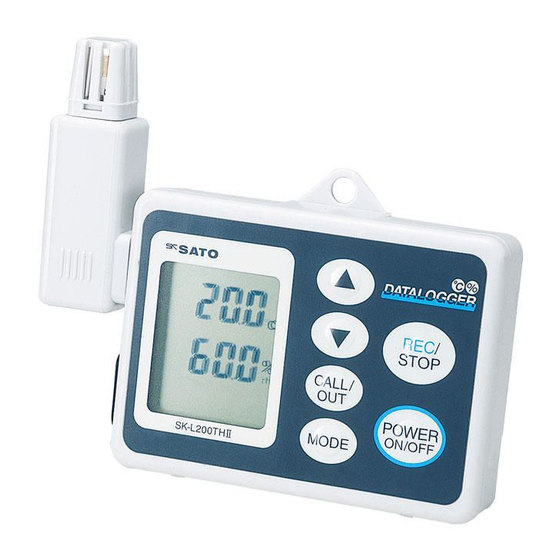
- Page 1 Instruction manual SK-L200 II Series Dataloggers No. 8161-00 Model SK-L200T II (Temperature Measurement) No. 8175-00 Model SK-L200TH IIα (Temperature/Humidity Measurement)
-
Page 2: Table Of Contents
Table of Contents ・ Introduction ....................1 ・ Safety Precautions..................2 ・ Overview ...................... 4 ・ Features....................... 4 1. What's in the Box? ..................8 2. Names and Functions of Parts ..............9 2-1. Main unit ....................9 2-2. Standard Probes.................. 15 3. -
Page 3: Introduction
Introduction Thank you for purchasing the SK-L200II Series Dataloggers. ・ This product is designed to measure temperature or temperature/humidity. Do not use it for other purposes. ・ Read this manual thoroughly before using. Keep the manual in a safe place for future reference whenever necessary. -
Page 4: Safety Precautions
Safety Precautions To use the Datalogger safely, follow the precautions below. ・ Never disassemble or modify the unit. Doing so may cause a malfunction. ・ The unit is precision-machined. Never drop the unit or knock it over. ・ Do not use the unit in a place exposed to direct sunlight or near a heat source. - Page 5 ・ Do not modify, forcibly pull, bend or tie the sensor cord. Placing heavy objects on the sensor cord or heating it will also damage the cord. ・ Do not wash or wipe this unit with alcohol, thinner, or other organic solvents.
-
Page 6: Overview
Overview Datalogger is a device that logs data of temperature and/or humidity and stores this data in its memory so that you can manage or analysis it on a computer. Features Storage of up to 8100 lines of data. ( → P.49) ●... - Page 7 3. Ends at… (limited amount) The Datalogger only collects a certain amount of data (up to 8100 lines) as specified by the user. This setting is ideal when you want to limit the amount of data to be collected. 4. By pages (partitioning) The Datalogger performs four different logging tasks in sequence by storing each task's data in the four divided memory blocks.
- Page 8 Displays the approximate amount of memory currently used. ● ( → P.52) Easy to determine how much more logging is possible. Probes can be interchangeablely used. ● The probes are fully compatible among the series models so that, in case of probe failure, it is easy to replace by interchanging with another probe.
- Page 9 Easy to use software program for data analysis ● The logged data can be fully utilized by plotting in graphs and displaying in real time. Data can also be saved in CSV format and analyzed by commercial spreadsheet software. −7−...
-
Page 10: What's In The Box
1. What's in the Box? The following items are included in the box. Check the box contents and place a check mark in the box next to each item. If you find any item missing, please contact the store where you purchased this product or our Service Network. -
Page 11: Names And Functions Of Parts
2. Names and Functions of Parts 2-1. Main Unit (For SK-L200T II and SK-L200TH II α Front view Rear view Left side view −9−... - Page 12 ① Sensor connector Temperature probe or temperature/humidity probe is connected. For connecting or removing the probe, please see section 1 "Installing the Probes and Batteries" of Chapter 3 "Getting Started." Never rotate the sensor unit. It will cause the device to fail. ②...
- Page 13 Function keys α (For SK-L200T II and SK-L200TH II ① UP/DOWN key ▲ ▼ ・ Pressing the key will increase the value. Pressing the key will decrease the value. ▲ ▼ Holding down will change the value rapidly. ▲ ▼...
- Page 14 ・ Pressing the CALL/OUT key while setting will return to the measurement state. ③ MODE key ・ Used to display Current Date and Time, ID, Logging Interval, Logging Option, Warning Thresholds or Preset Start. ④ REC/STOP key ・ Pressing the REC/STOP key for two seconds or more while measuring will start logging.
- Page 15 LCD display α (For SK-L200T II and SK-L200TH II ° ° ① Alphanumeric display (LCD) Displays the current reading of temperature and/or humidity or setting information. No humidity will be displayed on an SK-L200T II (temperature model). ② Alarm Lights up when the upper or lower threshold is reached. ③...
- Page 16 ④ mark Flashes when the battery power becomes low. If it happens, immediately replace the batteries. Data will be retained even if the batteries are replaced, but logging will stop the moment the batteries are removed from the unit and all settings will be reset to the defaults. ⑤...
-
Page 17: Standard Probes
2-2. Standard Probes Note: The probes are not interchangeable between the different types of models. The probe for SK-L200T II (temperature) cannot be used for SK-L200TH II α (temperature and humidity) and vice versa. For further information, please see the Specifications at the end of this manual. -
Page 18: Getting Started
3. Getting Started 3-1. Installing Probe and Batteries (1) Loosen the screw on the battery cover on the back of the main unit by rotating it counterclockwise with a coin or the like. Tip: The screw has been designed to be undetachable from the unit to prevent loosing it. -
Page 19: Setting Current Date And Time
3-2. Setting Current Date and Time (1) Press the POWER ON/OFF key for one second or more to turn the unit The LCD turns on to indicate that the SK-L200T II or SK-L200TH II α in the measurement state for temperature or temperature and humidity, respectively. - Page 20 ▲ ▼ (9) The "hour" display flashes. Use the key to set to "10". (For the hour) (10) Press the REC/STOP key to confirm the hour setting. Note: The Datalogger uses the 24-hour clock format. ▲ ▼ (11) The "minute" display flashes. Use the key to set to "30".
- Page 21 bring the unit to the ultra-low temperature or ultra-high temperature atmosphere or place it in such an environment. Doing so will damage the electronic circuit inside. The operating temperature range of the Datalogger is -10 to 60°C. For further information, please see "Specifica- tions"...
-
Page 22: Software Use Agreements
・ Sato Keiiryoki Mfg. Co., Ltd. shall not take any responsibilities for any damages caused by redistrubuted program by a user. −20 −... -
Page 23: Installing Datalogger For Windows
5. Installing DATALOGGER for Windows ・ Make sure that you have logged on as Administrator. If not, restart your computer and log on as Administrator. If your computer is managed by a network administrator, consult with him/her before making any modification to the system. - Page 24 Note that the proper communications will not be guaranteed when a USB hub is used. ・ The performance used by a serial conversion cable will be out of guarantee. ・ This DATALOGGER for Windows can be used with SK-L200II series dataloggers only.
- Page 25 The message below automatically appears. Click OK to proceed. A main menu of the installer for 64-bit appears. ※ Installation procedure of 64-bit and 32-bit is the same. Read this instruction replacing 64-bit to 32-bit when you install 32-bit. −23 −...
- Page 26 3. Installation of USB driver (1) Click "USB Driver" on the main menu. (2) The message below appears. Click “Install” to start installation. −24 −...
- Page 27 (3) A confirmation message on the USB controller appears. Click “Install” to continue the installation. (4) A confirmation message on ports (COM and LPT) appears. Click “Install” to continue the installation. −25 −...
- Page 28 (5) When the installation is successfully completed, a message confirming the installation appears. Click OK to end the installation of USB Driver. −26 −...
- Page 29 4. Installation of DATALOGGER for Windows (1) The main menu appears again. This time, click “DATALOGGER Software” −27 −...
- Page 30 (2) The license terms on Microsoft .NET Framework 4 are displayed. If you accept the terms of the License Agreement, click “Accept” to continue the installation. Note : If Microsoft .NET Framework 4 is already installed on your computer, the display automatically changes to the wizard for DATTERLOGGER for Windows.
- Page 31 (3) The installation of Microsoft .NET Framework 4 begins. After the installation of Microsoft .NET Framework 4 is ended, the window below appears. Click “Next >”. −29 −...
- Page 32 (5) The window below appears. Do not change the default installation folder. Click “Next >”. ※ Select the user of the computer for “Everyone” or “Just me” −30 −...
- Page 33 (6) “Confirm Installation” window appears. Click “next>” to start the installation. −31 −...
- Page 34 (7) When the installation is successfully completed, the ending window below appears. Click “Close”. −32 −...
- Page 35 (8) Click “Exit” on the main menu to finish the installer. Now the software installation is successfully completed, −33 −...
- Page 36 ■ Connecting the Datalogger to your computer 1. To run the software, click 「 Start 」→「 All Programs 」→「 SK-SATO 」 →「 DATALOGGER for Windows 」 . Press the “Power ON/OFF” button of the datalogger to turn the unit on and connect the datalogger to your computer using the provided USB cable.
- Page 37 2. Check the COM port. 1) Select 「 Device Manager 」 from 「 System and Security 」 or 「 Control Panel 」 and click it to check the COM port state. −35 −...
- Page 38 2) The Com port being used on your computer is displayed in Ports (COM & LPT). ※ The COM port number may vary depending on the computer being used or USB port connected. Be sure to confirm and set the serial port when you connect the datalogger.
- Page 39 3) From the Setting menu 「 Setting(S) 」 , click 「 Serial Port(S) 」 . Set the COM port number and click OK. 4) Message “Connection is correct” appears when the COM port is correctly set. Click OK. The software setting is now complete. For the details of usage of the software, refer to software help or the instruction manual that came with the product.
-
Page 40: Basic Operation
6. Basic Operation Let's start with an example to view data using DATALOGGER for Windows. Tip: Make sure that the date and time have been set on the Datalogger (see Chapter 3 “Getting Started”), and DATALOGGER for Windows has been installed to your computer (see Chapter 4 "Installing DATALOGGER for Windows"). - Page 41 α (5) Press the CALL/OUT key once. The SK-L200T II or SK-L200TH II returns to the measurement state for temperature or temperature and humidity, respectively. (6) Press and hold the REC/STOP key for two seconds or more. The LCD goes out, and then the REC mark and the leftmost bar of the memory indicator light up to indicate that the logging has started.
-
Page 42: Operating The Computer
(3) Click Start, all Programs, SK-SATO, and then click DATALOGGER for Windows to run the program. (4) From the Setting menu, click 「 Serial Port ( S ) 」 . - Page 43 (5) Set the serial port number. Tip: The serial port number may vary depending on the computer being used. (6) The message "Connection is correct" appears when the Datalogger and the computer are correctly connected. Click OK. Tip: If the message "Connection is incorrect" appears, check the serial port number again and make sure that the USB cable is plugged into the port properly.
- Page 44 (7) From the Transfer menu, click 「 Download ( D ) 」 . (8) When downloading is completed, check the data and click Close. Now you have successfully downloaded the test data. For details on how to use DATALOGGER for Windows, please refer to the online Help. (9) Erase the old data on the Datalogger.
- Page 45 ・ The logging option was “Ends at...” (limited amount) and logging ended because the quantity of logging data reached the set end-point. ・ The logging option was “By pages” (partitioning) and the logging ended because the memory became full (2000 readings in each page of four pages).
- Page 46 If the battery power becomes low (low battery state) during operation, the ● datalogger automatically does the following. ① While logging: Datalogger immediately stops logging and is powered off. (The collected data are stored) ② In standby for preset start: Er1 is displayed and the preset start is canceled.
-
Page 47: Advanced Operations
7. Advanced Operations The table below shows the operations performed by the Datalogger and computer. Datalogger Computer Turning Datalogger on or off Setting Current Date and Time Start/End logging Starting data download Setting the unit ID Setting the logging option Setting logging interval Setting preset start Confirming preset start info... - Page 48 Operation Procedures Turn on the Datalogger ▼ Display readings MODE key Display Datalogger ID ▼ ▲ ▼ Display current date and time ▼ MODE key Set current date and time REC/STOP key ▼ ▲ ▼ Display logging interval ▼ MODE key Set logging interval REC/STOP key ▼...
- Page 49 ▼ ▲ ▼ Display logging option ▼ MODE key Set logging option REC/STOP key ▼ ▲ ▼ Display warning thresholds ▼ MODE key Set warning thresholds REC/STOP key ▼ ▲ ▼ Display preset start ▼ Set preset start MODE key REC/STOP key ▼...
-
Page 50: Setting The Datalogger Id
7-1. Setting the Datalogger ID This function is used to identify multiple Dataloggers. An ID number from 1 to 9 can be assigned to each Datalogger used. Tips: You can only set the ID from DATALOGGER for Windows. Be sure to erase all the data stored on the Datalogger before setting. - Page 51 (4) From the Setting menu, click 「 ID ( D ) 」 . (5) The confirmation message appears. Click OK. −49 −...
-
Page 52: Setting The Logging Interval
(6) Choose the number and click Send. (7) Click OK to complete. 7-2. Setting the Logging Interval This function is used to specify the preferred logging interval. There are 14 types of logging interval to choose: in seconds (1, 2, 5, 10, 15, 30), and in minutes (1, 2, 5, 10, 15, 30, 60, 90). -
Page 53: Setting The Logging Option
Tip: You can set the logging interval from DATALOGGER for Windows. For further information, please refer to the online Help. (1) Press and hold the POWER ON/OFF key for one second or more to turn on the Datalogger. The LCD turns on to indicate that the SK-L200T II α... - Page 54 Once (default) When Once is chosen, the Datalogger keeps logging until the memory be- comes full. The Datalogger stops logging when 8100 lines of data are recorded. Start logging End logging Maximum 8100 lines Memory indicator Logged data : 1 to 1000 lines : 3001 to 4000 lines : 8100 lines Repeatedly (overwriting)
- Page 55 Memory indicator Logged data : 1 to 1000 lines : 7001 to 8100 lines : 8101 to 9000 lines : 9001 to 10000 lines From here, the dim bar is shifted to the right in succession. Ends at… (limited amount) With this logging option, you can specify the end-point for the Datalogger to stop logging.
- Page 56 four different tasks in sequence while storing each task’s data in one of the four different memory blocks (pages). This is ideal when you want to collect data from multiple sites using one Datalogger. Tips: The memory is used on a page-by-page basis. Therefore, even if there are less than 2000 stored data lines at the end of logging (REC/STP pressed), the entire page containing any number of lines becomes unavailable for further use.
- Page 57 How to set the logging option Tips: Aside from the steps below, you can also set the logging option from DATALOGGER for Windows. For further information, please refer to the online Help. Be sure to erase all the data stored on the Datalogger before setting the logging option.
- Page 58 ▲ ▼ (4) Use the key to set the number (1 to 4) representing the logging option desired on the upper LCD. (5) Press the REC/STOP key to confirm. (6) If the “Ends at…” (3 on the LCD) is chosen, proceed to step 7 below. For other options (1 for Once, 2 for Repeatedly, 3 for By pages), press the CALL/OUT key once.
- Page 59 Notes on logging Logging ends if the temperature measurement fails. In this state, “Er” appears on the display in the temperature section of the indicator LCD. The condition that caused the indicator to stop logging is “Abnormal pulses detected”. Note that the SK-L200TH II ends logging only if the probe is removed α...
-
Page 60: Setting The Upper And Lower Thresholds For Warning
7-4. Setting the upper and lower thresholds for warning This function is used to turn on the Alarm mark (Hi or Lo) when the temperature or humidity threshold is triggered. Note: No sound is produced while the Alarm mark is lit. Tip: Aside from the steps below, you can set this function from DATALOGGER for Windows. - Page 61 (5) Press the REC/STOP key to confirm. Next, set the lower limit for temperature. Tip: If the lower limit is not necessary, press the CALL/OUT key once. α The SK-L200T II or SK-L200TH II returns to the measurement state for temperature or temperature and humidity, respectively. ▲...
-
Page 62: Setting The Preset Start
7-5. Setting the Preset Start Setting the Date and Time This function is used to specify the date and time to start logging automatically. Notes: Starting this operation clears the logged data stored on the Datalogger depending on the logging option that has been set. Always download the necessary data before setting this function. - Page 63 Tip: Aside from the steps below, you can also set this function from DATALOGGER for Windows. For further information, please refer to the online Help. For example, if you want to start logging at 10:30 am, Sep. 1, 2012. (1) Press and hold the POWER ON/OFF key for one second or more to turn on the Datalogger.
- Page 64 (7) Press the REC/STOP key to confirm the month setting. ▲ ▼ (8) The "date" digits start flashing. Use the key to set to "1" (9) Press the REC/STOP key to confirm the date setting. ▲ ▼ (10) The "hour" digits start flashing. Use the key to set to "10"...
- Page 65 Canceling preset start Preset start can be canceled using any one of the three ways described below. A. Canceling from DATALOGGER for Windows (1) Start DATALOGGER for Windows. (2) From the Transfer ( T ) menu, click 「 Cancel Preset Start ( P ) 」 . (3) The message to confirm the cancel appears.
-
Page 66: Real-Time Communications
7-6. Real-time Communications This function is used to display the logged data of temperature and/or humidity on the computer screen in real time. (1) Using DATALOGGER for Windows ① Connect the Datalogger to your computer with the provided USB cable. ②... - Page 67 ⑤ From the Realtime menu, click 「 Start ( S ) 」 . ⑥ The Notes on Realtime window appears. Read it thoroughly and click OK to continue. −65 −...
- Page 68 ⑦ Create and type an easily identifiable name for the data. −66 −...
- Page 69 ⑧ Choose the "Storage Interval" from the list as necessary. Choose "None" if data is not to be stored automatically. −67 −...
- Page 70 ⑨ Once the "Stored Interval" has been set, the "Storage Items" fields become active. Click Change if you want to save the backup file in a different folder. The default folder is \Document folder. Tips: The SK6 format refers to the file format specially designed to be used with DATALOGGER for Windows.
- Page 71 ⑩ Click Start to return to the graph display and real-time communication starts. ⑪ To stop, click 「 End ( E ) 」 from the Realtime menu. −69 −...
- Page 72 ⑫ Click OK to confirm. Note: The battery life under real-time communication is about 500 hours. Check the battery life before using real-time communication. (2) Transmitting the data to other communication device During measurement, press the CALL/OUT key to start transmitting the data to a communication device.
- Page 73 �Output format � ● stx S -XXXX,-XXXX Cr Lf ※ First data stx R -XXXX,-XXXX Cr Lf ※ Second and subsequent data ・ Temperature/humidity data (if the value is minus) : − X X X X, − X X X X (if the value is plus) : (space) X X X X, (space) X X X X ・...
-
Page 74: Troubleshooting
8. Troubleshooting If an error occurs, one of the error codes listed below will be displayed on the LCD. Check the details of the error and take corrective actions as appropriate. If the problem persists, please contact the store where you purchased this product or our Service Network. - Page 75 ・The date and time chosen were ・Check the current and preset E r 4 prior to the current date and time. dates and times, and correct them as necessary. ・The logging operation was started ・Erase the data stored on the E r 5 (only By pages) when all pages were full with data.
-
Page 76: Specifications
9. Specifications 9-1. Main unit α SK-L200T II SK-L200TH II Model (Temperature) (Temperature & humidity) Cat. No. 8161-00 8175-00 Display range Temperature -45.0 to 205.0°C * -15.0 to 65.0°C * Humidity 10 to 99.9%rh * Resolution Temperature 0.1°C (-9.9 to 205.0°C) 0.1°C (-9.9 to 65.0°C) 1°C (-10°C or below) 1°C (-10°C or below) - Page 77 Display sampling Approx. 1 second Memory capacity Maximum 8100 readings. For By pages (memory partitioning logging option), 2000 readings x 4 pages Logging interval In seconds (1, 2, 5, 10, 15, 30) and in minutes (1, 2, 5, 10, 15, 30, 60, 90) Communication Operating ambient -10.0 to 60.0°C, no condensing...
-
Page 78: Standard Probes
9-2. Standard Probes SK-LT II - 1 SK-LT II - 2 SK-LTH II α SK-LTH II α Model (Plug-in type) (w/ sensor cord) (Plug-in type) (w/ sensor cord) 8162-00 8163-00 8176-00 8177-00 Cat. No. Thermistor Thermistor Sensor (Temp.) ----- High Polymeric resistance change (Humi.) humidity sensor -10.0 to 60.0°C... -
Page 79: Accuracy Of R. Humidity
ACCURACY OF R. HUMIDITY − 77 −... - Page 80 No. 3, Nishi Fukudacho, Kanda, Chiyodaku, Tokyo 101-0037 JAPAN TEL: + 81(0)3-3254-8117 FAX:(0)3-3254-8123 URL :http://www.sksato.co.jp/english/ M.07E...
Need help?
Do you have a question about the SK-L200 II Series and is the answer not in the manual?
Questions and answers