Table of Contents
Advertisement
Quick Links
Copyright
This publication, including all photographs, illustrations and software, is protected un-
der international copyright laws, with all rights reserved. Neither this manual, nor any
of the material contained herein, may be reproduced without written consent of the au-
thor.
Version 7.5a
Disclaimer
The information in this document is subject to change without notice. The manufac-
turer makes no representations or warranties with respect to the contents hereof and
specifically disclaims any implied warranties of merchantability or fitness for any par-
ticular purpose. The manufacturer reserves the right to revise this publication and to
make changes from time to time in the content hereof without obligation of the manu-
facturer to notify any person of such revision or changes.
Trademark Recognition
Microsoft, MS-DOS and Windows are registered trademarks of Microsoft Corp.
MMX, Pentium, Pentium-II, Pentium-III, Celeron are registered trademarks of Intel
Corporation.
Other product names used in this manual are the properties of their respective owners
and are acknowledged.
Federal Communications Commission (FCC)
This equipment has been tested and found to comply with the limits for a Class B digi-
tal device, pursuant to Part 15 of the FCC Rules. These limits are designed to provide
reasonable protection against harmful interference in a residential installation. This
equipment generates, uses, and can radiate radio frequency energy and, if not in-
stalled and used in accordance with the instructions, may cause harmful interference
to radio communications. However, there is no guarantee that interference will not oc-
cur in a particular installation. If this equipment does cause harmful interference to
radio or television reception, which can be determined by turning the equipment off
and on, the user is encouraged to try to correct the interference by one or more of the
following measures:
−
Reorient or relocate the receiving antenna.
−
Increase the separation between the equipment and the receiver.
−
Connect the equipment onto an outlet on a circuit different from that to which
the receiver is connected.
−
Consult the dealer or an experienced radio/TV technician for help.
Shielded interconnect cables and a shielded AC power cable must be employed with
this equipment to ensure compliance with the pertinent RF emission limits governing
this device. Changes or modifications not expressly approved by the system's manu-
facturer could void the user's authority to operate the equipment.
Preface
Advertisement
Table of Contents

Related Manuals for ECS K7SOM+


Summary of Contents for ECS K7SOM+
- Page 1 Preface Copyright This publication, including all photographs, illustrations and software, is protected un- der international copyright laws, with all rights reserved. Neither this manual, nor any of the material contained herein, may be reproduced without written consent of the au- thor.
- Page 2 Declaration of Conformity This device complies with part 15 of the FCC rules. Operation is subject to the follow- ing conditions: − This device may not cause harmful interference, and − This device must accept any interference received, including interference that may cause undesired operation.
-
Page 3: Table Of Contents
Preface CHAPTER 1 Introducing the Mainboard Introduction ....................1 Checklist .....................1 Standard Items ....................1 Features .....................2 Choosing a Computer Case ...............4 Mainboard Components ................5 CHAPTER 2 Installing the Mainboard Safety Precautions..................7 Quick Guide ....................7 Installing the Mainboard in a Case..............8 Checking Jumper Settings ................8 Setting Jumpers .................... - Page 4 Features Setup Page..................30 CPU PnP Setup Page ..................32 Hardware Monitor Page................. 33 Change Password................... 34 Change or Remove the Password ..............34 Exit ........................ 34 CHAPTER 4 Using the Mainboard Software About the Software CD-ROM ..............35 Auto-installing under Windows 98/ME/2000/XP ........35 Running Setup ....................
-
Page 5: Introducing The Mainboard
Introducing the Mainboard Thank you choosing the K7SOM+ mainboard. This mainboard has a Socket-A support for the AMD K7 processors. The Socket-A processor’s front-side bus speed is 266MHz. This mainboard integrates the SiS740 Northbridge and SiS962L Southbridge chipsets that support DDR 266MHz, Ultra DMA 33/66/100/133 function and remarkably high system performance under all types of system operations. -
Page 6: Features
• Supports Socket-462 processor Processor • Supports AMD Athlon XP/Athlon/Duron processors • Supports 266 MHz Front-Side Bus Chipset The SiS740 Northbridge and SiS962L Southbridge in this chipset in accordance with an innovative and scalable architecture with proven reliability and performance. A few of the chipset’s advanced features are: •... - Page 7 Onboard I/O The mainboard has a full set of I/O ports and connectors: Ports • Two PS/2 ports for mouse and keyboard • One serial port • One VGA port • One parallel port • Six USB2.0 ports (four back-panel ports, onboard USB header providing two extra ports) •...
-
Page 8: Choosing A Computer Case
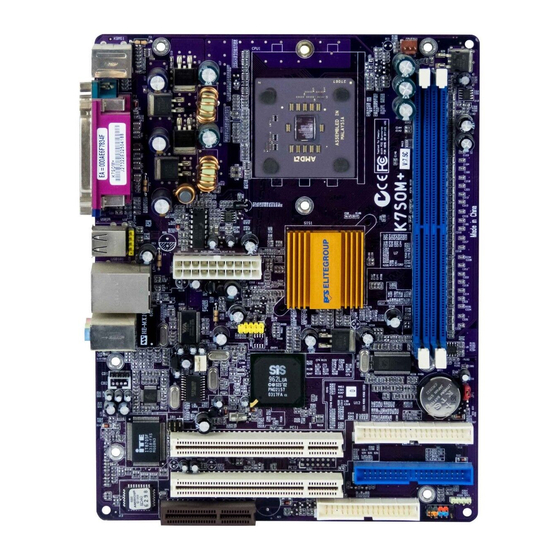
There are many types of computer cases on the market. The mainboard com- plies with the specifications for the micro-ATX system case. Some features on the mainboard are implemented by cabling connectors on the mainboard to indicators and switches on the system case. Ensure that your case supports all the features required. - Page 10 Table of Mainboard Components Label Component ATX1 Standard 20-pin ATX power connector AUDIO1 Front panel MIC/Speaker Out header BAT1 Three volt realtime clock battery CD-in connector CNR1 Communications Networking Riser slot CPUFAN1 CPU cooling fan CPU Socket Socket A for AMD Athlon/Duron CPUs DDR1 ~ DDR2 Two 184-pin DDR DIMM sockets FDC1...
-
Page 11: Installing The Mainboard
Installing the Mainboard Follow these safety precautions when installing the mainboard: • Wear a grounding strap attached to a grounded device to avoid damage from static electricity. • Discharge static electricity by touching the metal case of a safely grounded object before working on the mainboard. •... -
Page 12: Installing The Mainboard In A Case
Refer to the following illustration and instructions for installing the mainboard in a case: This illustration shows an ex- 2. Secure the mainboard with ample of a mainboard being screws where appropriate. installed in a tower-type case: Note: Do not overtighten the screws as this can stress the main- board. -
Page 13: Checking Jumper Settings
Checking Jumper Settings The following illustration shows the location of the mainboard jumpers. Pin 1 is labeled. Jumper Settings Jumper Type Description Setting (default) 3-pin Clear CMOS 1-2: Clear CMOS jumper 2-3: Normal JP1: Clear CMOS Jumper Use this jumper to clear the contents of the CMOS memory. You may need to clear the CMOS memory if the settings in the Setup Utility are incorrect and prevent your mainboard from operating. -
Page 14: Connecting Case Components
After you have installed the mainboard into a case, you can begin connecting the mainboard components. Refer to the following: Connect the power connector from the power supply to the ATX1 connector on the mainboard. Connect the CPU cooling fan cable to CPUFAN1. -
Page 15: The Sw1 Connector
SPK1: Internal speaker Signal Name SPKR The SW1 Connector This panel connector provides a set of switch and LED connectors found on ATX case. Refer to the table below for information. Signal Signal HD_LED_P FP PWR/SLP HD_LED_N FP PWR/SLP RESET_SW_N POWER_SW_P RESET_SW_P POWER_SW_N... -
Page 16: Installing Hardware
Installing the Processor Caution: When installing a CPU heatsink and cooling fan make sure that you DO NOT scratch the mainboard or any of the surface-mount resistors with the clip of the cooling fan. If the clip of the cooling fan scrapes across the mainboard, you may cause serious damage to the mainboard or its components. - Page 17 CPU Installation Procedure The following illustration shows CPU installation components: Note: The pin-1 corner is marked with an arrow Follow these instructions to install the CPU: Pull the CPU socket locking lever away from the socket to unhook it and raise the locking lever to the upright position.
-
Page 18: Installing Memory Modules
Installing Memory Modules This mainboard accommodates two 184-pin 2.5V unbuffered Double Data Rate SDRAM (DDR SDRAM) Dual Inline Memory Module (DIMM) sockets, and supports up to 1.0 GB of 266 MHz DDR SDRAM. DDR SDRAM is a type of SDRAM that supports data transfers on both edges of each clock cycle (the rising and falling edges), effectively doubling the memory chip’s data throughput. -
Page 19: Installing A Hard Disk Drive/Cd-Rom
Install any remaining DIMM modules. Installing a Hard Disk Drive/CD-ROM This section describes how to install IDE devices such as a hard disk drive and a CD-ROM drive. About IDE Devices Your mainboard has a primary and secondary IDE channel interface (IDE1 and IDE2). - Page 20 stalled. Installing a CD-ROM/DVD Drive Install the CD-ROM/DVD drive into the drive cage in your system case. Plug the IDE cable into IDE1 (A). If you have already installed an HDD, use the other connec- tor on the IDE cable. Note: Ribbon cable connectors are usually keyed so that they can only be installed correctly on the device...
-
Page 21: Installing A Floppy Diskette Drive
Installing a Floppy Diskette Drive The mainboard has a floppy diskette drive (FDD) interface and ships with a diskette drive ribbon cable that supports one or two floppy diskette drives. You can install a 5.25-inch drive and a 3.5-inch drive with various capacities. The floppy diskette drive cable has one type of connector for a 5.25-inch drive and another type of connector for a 3.5-inch drive. - Page 22 PCI Slots PCI slots are used to install expansion cards that have the 32-bit PCI interface. CNR Slot This slot is used to insert CNR cards with Modem and Audio func- tionality. Note: Before installing an add-on card, check the documentation for the card carefully.
-
Page 23: Connecting Optional Devices
Connecting Optional Devices Refer to the following for information on connecting the mainboard’s optional devices: AUDIO1: Front Panel Audio header This header allows the user to install auxiliary front-oriented microphone and line-out ports for easier access. Signal Name Function AUD_MIC Front Panel Microphone input signal AUD_GND Ground used by Analog Audio Circuits... - Page 24 USB2: Extended USB header The mainboard has USB ports installed on the rear edge I/O port array. Some computer cases have a special module that mounts USB ports at the front of the case. If you have this kind of case, use auxiliary USB connectors USB2 to connect the front-mounted ports to the mainboard.
-
Page 25: Connecting I/O Devices
IR1: Serial infrared port The mainboard supports an Infrared (IR1) data port. Infrared ports allow the wireless exchange of information between your computer and similarly equipped devices such as printers, laptops, Personal Digital Assistants (PDAs), and other computers. Signal Name Function Not connected No pin... - Page 26 External Connector Color Coding Many connectors now use standard colors as shown in the table below. Connector Color Audio line-in Light blue Audio line-out Lime Digital monitor/flat panel White IEEE 1394 Grey Microphone Pink MIDI/game Gold Parallel Burgundy PS/2-compatible keyboard Purple PS/2-compatible mouse Green...
-
Page 27: Using Bios
Using BIOS The computer uses the latest AMI BIOS with support for Windows Plug and Play. The CMOS chip on the mainboard contains the ROM setup instructions for configuring the mainboard BIOS. The BIOS (Basic Input and Output System) Setup Utility displays the system's configuration status and provides you with options to set system parameters. -
Page 28: Running The Setup Utility
Running the Setup Utility Each time your computer starts, before the operating system loads, a mes- sage appears on the screen that prompts you to “Hit <DEL> if you want to run SETUP”. When you see this message, press the Delete key and the Main menu page of the Setup Utility appears on your monitor. -
Page 29: Standard Cmos Features
to change the values for the option. Use the cursor arrow keys to scroll through the items in the submenu. In this manual, default values are enclosed in parenthesis. Submenu items are denoted by a triangle Standard CMOS Features Use this page to set basic information such as the date, the time, the IDE de- vices, and the diskette drives. -
Page 30: Advanced Setup Page
Advanced Setup Page Use this page to set more advanced information about your system. Take some care with this page. Making changes can affect the operation of your computer. AMIBIOS SETUP – ADVANCED SETUP (C) 2000 American Megatrends, Inc. All Rights Reserved Shared Memory Size 32 MB Quick Boot... - Page 31 Floppy Drive Swap If you have two diskette drives installed and you enable this item, drive A be- comes drive B and drive B becomes drive A. Floppy Drive Seek If you enable this item, your system will check all floppy disk drives at start up. Disable this item unless you are using an old 360KB drive.
-
Page 32: Power Management Setup Page
Power Management Setup Page This page sets some of the parameters for system power management opera- tion. AMIBIOS SETUP – POWER MANAGEMENT SETUP (C) 2000 American Megatrends, Inc. All Rights Reserved ACPI Aware O/S Power Management Enabled Suspend Time Out Disabled Hard Disk Time Out Disabled... -
Page 33: Pci / Plug And Play Setup
PCI / Plug and Play Setup This page sets some of the parameters for devices installed on the PCI bus and devices that use the system plug and play capability. AMIBIOS SETUP – PCI / PLUG AND PLAY SETUP (C) 2000 American Megatrends, Inc. All Rights Reserved Plug and Play Aware O/S Primary Graphics Adapter Allocate IRQ to PCI VGA... -
Page 34: Load Optimal Settings
Load Optimal Settings If you select this item and press Enter a dialog box appears. If you press Y, and then Enter, the Setup Utility loads a set of fail-safe default values. These default values are not very demanding and they should allow your system to function with most kinds of hardware and memory chips. - Page 35 Parallel Port Mode Use this item to set the parallel port mode. You can select SPP (Standard Parallel Port), ECP (Extended Capabilities Port), EPP (Enhanced Parallel Port), or ECP + EPP. Parallel Port IRQ Use this item to assign either IRQ 5 or 7 to the parallel port. Parallel Port DMA Use this item to assign a DMA channel to the parallel port.
-
Page 36: Cpu Pnp Setup Page
CPU PnP Setup Page This page lets you manually configure the mainboard for the CPU. The system will automatically detect the kind of CPU that you have installed and make the appropriate adjustments to the items on this page. AMIBIOS SETUP – CPU PnP SETUP (C) 2000 American Megatrends, Inc. -
Page 37: Hardware Monitor Page
Hardware Monitor Page This page sets some of the parameters for the hardware monitoring function of this mainboard. AMIBIOS SETUP – HARDWARE MONITOR (C) 2000 American Megatrends, Inc. All Rights Reserved ** System Hardware *** Vcore 1.616V Vcc 2.5V 2.496V Vcc 3.3V 3.392V 4.945V... -
Page 38: Change Password
Change Password If you highlight this item and press Enter, a dialog box appears which lets you enter a Supervisor password. You can enter no more than six letters or num- bers. Press Enter after you have typed in the password. A second dialog box asks you to retype the password for confirmation. -
Page 39: Using The Mainboard Software
Using the Mainboard Software The support software CD-ROM that is included in the mainboard package contains all the drivers and utility programs needed to properly run the bun- dled products. Below you can find a brief description of each software program, and the location for your mainboard version. -
Page 40: Running Setup
Setup Tab Setup Click the Setup button to run the software installation program. Select from the menu which software you want to install. Browse The Browse CD button is the standard Windows command that allows you to open Windows Explorer and show the contents of the support CD. - Page 41 Note: The following screens are examples only. The screens and driver lists will be different according to the mainboard you are installing. The mainboard identification is located in the upper left-hand corner. Click Next. The following screen appears: Check the box next to the items you want to install. The default options are recommended.
-
Page 42: Manual Installation
Insert the CD in the CD-ROM drive and locate the PATH.DOC file in the root directory. This file contains the information needed to locate the drivers for your mainboard. Look for the chipset and mainboard model; then browse to the directory and path to begin installing the drivers. - Page 43 We strongly recommend users to install this free anti-virus software to help protect your system against viruses. MediaRing Talk – Telephony Software To install the MediaRing Talk voice modem software for the built-in modem, go directory \UTILITY\MEDIARING TALK, then MRTALK- SETUP72.EXE to install the application software.
Need help?
Do you have a question about the K7SOM+ and is the answer not in the manual?
Questions and answers