Table of Contents
Advertisement
Quick Links
We advise you to read this manual carefully, which contains all the instructions for maintaining the
appliance's aesthetic and functional qualities. For further information on the product: www.smeg.com
PRECAUTIONS
General safety instructions
Risk of personal injury
• During use the appliance and
its accessible parts become
very hot. Keep children well
away from the appliance.
• Protect your hands by wearing
oven gloves when moving food
inside the oven.
• Never try to put out a fire or
flames with water: Turn off the
appliance and smother the
flames with a fire blanket or
other appropriate cover.
914779645/B
3
14
3
7
8
8
8
8
8
9
9
9
9
9
10
10
11
11
12
12
13
13
13
13
• This appliance may only be
used by children aged 8 years
and over, and by people of
reduced physical, sensory or
mental capacity, or lacking in
experience in the use of
electrical appliances, provided
that they are supervised or
have been given instructions on
the safe use of the appliance
and of the hazards associated
with it.
• Children must not play with the
appliance.
• Keep children under the age of
14
15
17
18
19
19
19
19
20
20
21
22
23
23
24
24
27
28
29
30
31
PRECAUTIONS - 3
Advertisement
Table of Contents

Related Manuals for Smeg SYD4110-1


Summary of Contents for Smeg SYD4110-1
-
Page 1: Table Of Contents
Using the hob Instructions for the installer We advise you to read this manual carefully, which contains all the instructions for maintaining the appliance’s aesthetic and functional qualities. For further information on the product: www.smeg.com PRECAUTIONS General safety instructions • This appliance may only be... - Page 2 eight at a safe distance unless the flames, for example with a they are constantly supervised. lid or a blanket. • Keep children under the age of • The appliance becomes very 8 away from the appliance hot during use. Take care never when it is in use.
- Page 3 COMPARTMENT (IF • If the power cable becomes AVAILABLE) OR NEAR THE damaged, contact technical APPLIANCE. support immediately to arrange • DO NOT USE AEROSOLS IN for it to be replaced in order to THE VICINITY OF THIS avoid possible hazards. APPLIANCE WHILST IT IS IN •...
- Page 4 inserted as far as they will go model) by placing it on the into the side guides. The bottom as a support for mechanical safety locks that cooking. prevent them from being • If you wish to use greaseproof removed must face downwards paper, place it so that it will not and towards the back of the interfere with the hot air...
-
Page 5: Installation
dishwasher. requirements regarding • Never use the oven door to ventilation. lever the appliance into place • The settings for this appliance when fitting. are shown on the gas setting • Avoid exerting too much label. pressure on the door when •... -
Page 6: Appliance Purpose
system safety standards. be kept in mind that the appliance may be equipped with an updated version of the • Use cables that can withstand system, and as such, all that appears on the temperatures of at least 90°C. display may differ from those in the manual. •... -
Page 7: Information For European Control Bodies
light sources. Plastic packaging Danger of suffocation • Do not let children play with the plastic bags. Information for European Control Bodies • The light sources contained in the appliance Fan forced mode are declared suitable for operation at the ECO function used to define the energy ambient temperature ≥300°C and intended efficiency class complies with the specifications for use in high temperature applications such... -
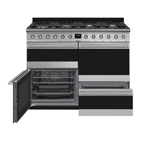
Page 8: Description
DESCRIPTION General description 1 Hob 2 Control panel 3 Auxiliary oven seal 4 Auxiliary oven light 5 Auxiliary oven door 6 Multifunction oven door 7 Left multifunction oven light 8 Fan 9 Left multifunction oven seal 10 Right multifunction oven light 11 Storage compartment 12 Right multifunction oven door 13 Right multifunction oven seal... -
Page 9: Hob
AUX = Auxiliary Burner R = Rapid Burner SR = Semi-rapid Burner UR2 = Ultra Rapid Burner Control panel 1 Hob burner knobs 4 Auxiliary oven variable grill indicator light For lighting and adjusting the hob burners. Press The indicator light comes on to indicate that the auxiliary oven is heating up. -
Page 10: Other Parts
required function, set the cooking temperature contact with food are made of materials that using the temperature knob. comply with the provisions of current legislation. 8 Upper multifunction oven indicator light • Original supplied and optional accessories The indicator light comes on to indicate that the can be requested to Authorised Assistance oven is heating up. -
Page 11: Use
Preliminary operations Tray rack The tray rack has to be inserted into the tray. In See General safety instructions. this way fat can be collected separately from the food which is being cooked. • Remove any protective film from the outside or inside of the appliance, including accessories. -
Page 12: Using The Storage Compartment (Where Present)
Correct positioning of the flame-spreader Opening and closing the door of the crowns and burner caps multifunction oven Before lighting the hob burners, make sure that Multifunction ovens are equipped with a swing the flame-spreader crowns are correctly door. To open, pull the door handle towards positioned in their housings with their respective you. -
Page 13: Digital Programmer
Digital programmer RAPID DEFROST Activating the fan on its own ensures a uniform distribution of room temperature air inside the oven, allowing any type of food to be defrosted. FAN ASSISTED Intense and uniform cooking. Ideal for biscuits, cakes and cooking on more than one level. - Page 14 current time (for example, the cooking end appear, alternating with the time shown is 18:30). current time. 6. Press the key to set the cooking 3. Use the increase and decrease end time. (for example, 19:30). keys to set the required minutes of cooking. 4.
-
Page 15: Cooking Advice
• Use a meat thermometer when roasting 2. Use the increase and decrease meat, or simply press on the roast with a keys to set the required minutes. spoon. If it is hard, it is ready; if not, it needs 3. -
Page 16: Cooking Information Table (Multifunction Oven)
Advice for defrosting and proving this way, the liquid from the defrosting food drains away from the food. • Place frozen foods without their packaging in a lidless container on the first shelf of the • The most delicate parts can be covered with oven. -
Page 17: Cooking Information Table (Auxiliary Oven)
Weight Temp. Time Food Function Shelf (Kg) (°C) (minutes) Jam tarts CIRCULAIRE 20 - 25 Paradise cake CIRCULAIRE 55 - 60 Profiteroles CIRCULAIRE 80 - 90 Sponge cake CIRCULAIRE 150 - 160 55 - 60 Rice pudding CIRCULAIRE 55 - 60 Brioches CIRCULAIRE 30 - 35... -
Page 18: Knobs
Cleaning the door them thoroughly and return them to the hob. The continuous contact between the Cleaning the door glazing pan supports and the flame can cause The glass in the door should always be kept modifications to the enamel over time in thoroughly clean. -
Page 19: Cleaning The Oven Cavity
Removing the internal glass panes Auxiliary oven door 1. Remove the internal glass panel by pulling For easier cleaning the internal glass panes of the rear part gently upwards, following the the door can be removed. movement indicated by the arrows (1). Use kitchen paper to clean. -
Page 20: Cleaning The Roof Of The Oven (Only For Some Models/Cavities)
Avoid letting food residue dry inside the oven Cleaning the roof of the oven (only cavity, as this could damage the enamel. for some models/cavities) Take out all removable parts before cleaning. For easier cleaning, it is recommended to See General safety instructions. remove: •... -
Page 21: Vapor Clean (On Some Models Only)
Vapor Clean (on some models only) 3. Use a non-scratch sponge with brass filaments on hard to remove deposits. 4. In case of grease residues use specific oven See General safety instructions. cleaning products. 5. Remove the residual water inside the oven. The Vapor Clean function is an assisted 6. -
Page 22: Installation
5. Replace the light bulb with one of the same Take care not to scratch the enamel of type (40 W). the oven cavity wall. 6. Refit the cover. Ensure the moulded part of the glass (A) is facing the door. 4. - Page 23 comply with the applicable standard. (serigraphed on the hose itself). Connection using a rubber hose complying with current standards is only permitted if the hose can be inspected along its entire length. The inside diameter of the hose must be 8 mm for LPG and 13 mm for Natural gas and Town gas.
- Page 24 comply with the applicable standard. Extraction of the combustion products The combustion products may be extracted by means of hoods connected to a natural draught chimney whose efficiency is certain or via forced extraction. An efficient extraction system requires precision planning by a specialist qualified in this area and must comply with the positions and clearances indicated by the applicable standards.
-
Page 25: Gas Types And Countries
Replacing nozzles Light the burner and turn it to the minimum position. Extract the gas cock knob and turn the adjustment screw next to the gas cock spindle (depending on the model) until the correct minimum flame is achieved. Refit the knob and verify that the burner flame is stable. -
Page 26: Burner And Nozzle Characteristics Tables
Gas types 5 LPG G30/31 28-30/37 mbar G30/31 • • • • • • 30/30 mbar G30/31 • • • 6 LPG G30/31 37 mbar G30/31 • 7 Town Gas G110 8 mbar G110 • • It is possible to identify the available gas types based on the country the appliance is to be installed in. -
Page 27: Positioning
7 Town gas G110 – 8 mbar Rated heating capacity (kW) Nozzle diameter (1/100 mm) Pre-chamber (printed on nozzle) (/8) (/2) (/3) 0190 Reduced flow rate (W) 1000 The nozzles not provided are available at Authorised Service Centres. Positioning Appliance overall dimensions See General safety instructions. -
Page 28: Electrical Connection
Appliance dimensions 2. Place the upstand on the hob. 3. Align the slots of the upstand (B) with the screws (A). The upstand provided is an integral part of the product. It must be fastened to the appliance prior to installation. Mounting the plinth 636,5 636,5... -
Page 29: Instructions For The Installer
on all connections. DO NOT use naked The appliance can work in the following modes: flames to search for leaks. 220-240 V 1N~ • Turn on all the burners separately and at 3 x 6 mm ² then all together to make sure that the gas valve, burner and ignition are working three-core cable properly.
Need help?
Do you have a question about the SYD4110-1 and is the answer not in the manual?
Questions and answers