Table of Contents
Advertisement
Quick Links
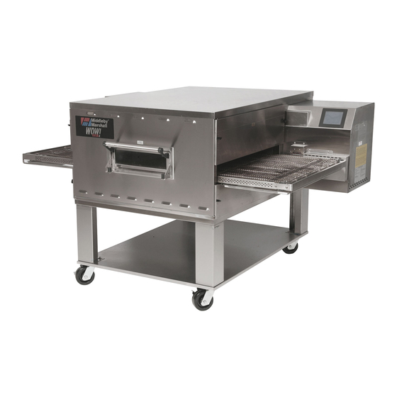
PS745 Series
Gas
Domestic & Std. Export
ENGLISH
PS745 Series Gas Ovens
Model:
• PS745G Gas
OWNER'S OPERATING AND
INSTALLATION MANUAL
for domestic and standard export ovens
©2012 Middleby Marshall Inc.
is a registered trademark of Middleby Marshall, Inc. All rights reserved.
Middleby Cooking Systems Group • 1400 Toastmaster Drive • Elgin, IL 60120 • (847)741-3300 • FAX (847)741-4406
Combinations:
• Single Oven
• Double Oven (Two-Stack)
• Triple Oven (Three-Stack)
P/N 68690
September 2012
Advertisement
Table of Contents

Subscribe to Our Youtube Channel
Related Manuals for Middleby Marshall PS745 Series


Summary of Contents for Middleby Marshall PS745 Series
- Page 1 INSTALLATION MANUAL for domestic and standard export ovens ©2012 Middleby Marshall Inc. is a registered trademark of Middleby Marshall, Inc. All rights reserved. Middleby Cooking Systems Group • 1400 Toastmaster Drive • Elgin, IL 60120 • (847)741-3300 • FAX (847)741-4406...
-
Page 2: Retain This Manual For Future Reference
Installation section of this Manual. For domestic and standard export ovens, instructions are included in the Gas Conversion Kit. It is suggested to obtain a service contract with a Middleby Marshall Authorized Service Agent. WARNING POST, IN A PROMINENT LOCATION, THE EMERGENCY TELEPHONE NUMBER OF YOUR LOCAL GAS SUPPLIER AND INSTRUCTIONS TO BE FOLLOWED IN THE EVENT YOU SMELL GAS. - Page 3 © 2012 - Middleby Marshall, A Middleby Company. The Middleby Marshall logo is a registered trademark of Middleby Marshall, A Middleby Company. Middleby Marshall Inc. • 1400 Toastmaster Drive • Elgin, Illinois 60120-9272 U.S.A. • (847) 741-3300 • FAX: (847) 741 4406...
- Page 4 TABLE OF CONTENTS Page Page SECTION 1 – DESCRIPTION ..........1 SECTION 3 – OPERATION ..........14 LOCATION AND DESCRIPTION OF CONTROLS 16 OVEN USES ............. 1 II. OVEN COMPONENTS ..........1 II. NORMAL OPERATION, STEP-BY-STEP ....17 A. Conveyor Motor Drive ........1 A.
-
Page 5: Section 1 - Description
SECTION 1 – DESCRIPTION Figure 1-1. Oven Components I. OVEN USES PS745 Series Ovens can be used to bake and/or cook a wide variety of food products, such as pizza, pizza –type products, cookies, sandwiches and others. II. OVEN COMPONENTS – see Figure 1-1. -
Page 6: Oven Specifications
I. OVEN SPECIFICATIONS Table 1-1 Dimensions Single Oven Double Oven Triple Ove Overall Height 48-3/16″ (1219mm) 62-3/4″ (1575mm) 78-11/16″ (1981mm) Overall Depth 60″ (1524mm) 60″ (1524mm) 60″ (1524mm) Overall Length 76-1/2″ (1930mm) 76-1/2″ (1930mm) 76-1/2″ (1930mm) Conveyor Width – belt width is 32″ 33-1/2″... -
Page 7: Section 2 - Installation
SECTION 2 – INSTALLATION WARNING – After any conversions, readjustments, or service work on the oven: • Perform a gas leak test. • Test for proper combustion and gas supply. • Test for correct air supply, particularly to the • Check that the ventilation system is in operation. burner blower. -
Page 8: Type Of Installation
PS745 OVEN INSTALLATION REQUIRED KITS AND EQUIPMENT PS745 PS745 PS745 PS745 Gas Oven Single Oven DoubleOven TripleOven Installation Option Base w/ OptionBase w/ OptionBase w/ TYPE OF INSTALLATION 15″ Legs, 6″ Legs, Casters& Top Casters & Top Casters & Top P/N61033 P/N67025 P/N67026... - Page 9 Figure 2-2. Model PS745 Single Oven Option Base with Legs and Top HARDWARE BAG 5, 6, 7, 10 & 11 PARTS LIST FOR PS745 SERIES SINGLE OVEN OPTION - BASE w/15″ LEGS & TOP 67025 ITEM NO. PART NO. DESCRIPTION...
- Page 10 Figure 2-3. Model PS745 Double Oven Option Base with Legs and Top HARDWARE BAG 5, 6, 7, 10 & 11 PARTS LIST FOR PS745 SERIES DOUBLE OVEN OPTION - BASE w/6″ LEGS & TOP 67026 ITEM NO. PART NO. DESCRIPTION...
- Page 11 Figure 2-4. Model PS745 Triple Oven Option Base with Outriggers and Top HARDWARE BAG 7, 8, 9, 10, 11, 12, 13, 14, & 17 PARTS LIST FOR PS745 SERIES TRIPLE OVEN OPTION - BASE w/CASTERS & TOP 66164 ITEM NO. PART NO. DESCRIPTION...
-
Page 12: Ventilation System
III. VENTILATION SYSTEM B. Recommendations NOTE THAT THE HOOD DIMENSIONS SHOWN IN F I G U R E 2 - 5 A R E R E C O M M E N D A T I O N S O N L Y . IMPORTANT LOCAL, NATIONAL AND INTERNATIONAL CODES MUST BE FOLLOWED WHEN INSTALLING THE... - Page 13 IV. ASSEMBLY Figure 2-6. Leg extension and casters installation A. Top Panel and Base Pad Assembly Install the four leg extensions onto the base pad using the 3/8″-16 × 1″ screws, 3/8″ flat washers, and 3/8″ lockwashers supplied in the Base Pad Kit. See Figure 2-6.
- Page 14 For quad ovens, lock the two Gas oven cavities be stacked BY AUTHORIZED PERSONEL. front casters. Contact your Middleby Marshall Authorized Service Agent for Figure 2-10. Top panel installation complete stacking instructions. Stack an oven cavity on top of the lower oven. Check the following: #10-32 ×...
- Page 15 D. Conveyor Installation Figure 2-13. Conveyor placement Unfold the conveyor as shown in Figure 2-12. Then, begin to slide the conveyor into the end of the oven. The conveyor can only be installed from the end of the oven with the drive motor. Crumb tray support Continue moving the conveyor into the oven until the frame...
-
Page 16: Electrical Supply
CONVEYOR BELT REVERSAL If it is necessary to add or remove conveyor links to achieve the correct tension, OR if it is necessary to reverse the Conveyor belt reversal consists of three steps: conveyor belt for correct orientation, the belt will need to be removed from the conveyor frame. -
Page 17: Gas Supply
CAUTION: The terms of the oven’s warranty require all very slowly. start-ups, conversions and service work to be performed by a Middleby Marshall Authorized After the initial gas turn-on, the manual Service Agent. shutoff valve must remain open except during pressure testing as outlined in the above steps or when necessary during service maintenance. - Page 18 B. Connection Figure 2-18. Flexible Gas Hose Installation Check the oven’s gas supply requirements before making the gas utility connection. Gas supply requirement are listed on the oven’s serial plate and in Table 1-4. Gas Orifice and Pressure Specifications (in Section 1, Description). 1/2″...
- Page 19 Figure 2-20. Burner Assembly Adjusting the Minimum Pressure Setting Disconnect pressure feedback connection (if appcable). Connect a suitable pressure gauge to pipe line or to outlet pressure tap of gas control concerned, to measure burner pressure (measuring point must be as near to burner as possible).
-
Page 20: Section 3 - Operation
SECTION 3 - OPERATION LOCATION AND DESCRIPTION OF CONTROLS "BLOWER" Switch: Turns the blowers and monitors the oven temperature. Settings on cooling fans on and off. The HEAT Switch has the Digital Temperture Controller control the no effect unless the BLOWER Switch is in the activation of the burner. Keypad controls allow “ON” position. the operator to select the cooking temperature and monitor oven operation. "HEAT" Switch: Allows the burner to activate. NOT SHOWN: Activation is determined by the settings on the Digital Temperature Controller. Machinery and Control Compartment Safety Switches: Disconnect electrical power to the controls and blowers "CONVEYOR" Switch: Turns the conveyor when EITHER the machinery compartment door OR the drive motor on and off. -
Page 21: Normal Operation - Step-By-Step
II. NORMAL OPERATION - STEP-BY-STEP 8. (Optional) Press the Temperature ( ) key to show the Ac- tual Temperature in the display, and wait for the "ACTUAL A. DAILY STARTUP PROCEDURE TEMP" light to turn on. This allows you to monitor the oven 1. Check that the circuit breaker/fused disconnect is in the on position. Check that the window is closed. temperature as it rises to 2. Turn the "BLOWER" switch to the “ON” ("I") position. the setpoint. 3. Turn the "CONVEYOR" ( 9. Allow the oven to preheat wait ) switch to the “ON” for 10 minutes after it has ("I") position. reached the set point temperature. B. D A I LY S H U T D O W N PROCEDURE 4. If necessary, adjust the conveyor speed setting... -
Page 22: Quick Reference: Digital Temperature Controller
III. QUICK REFERENCE: DIGITAL TEMPERATURE CONTROLLER Display "HEAT ON" Light Shows the Set Point Lights when the or the Actual Tem- burner is in perature in degrees operation. Fahrenheit (F) or Celsius (C). "SP LOCK" Light Lights when the set "SET PT" (set- point is locked out from changes. This point) Light setting can only be Lights when the set changed by service point is shown in personnel. the display. OVERTEMP Light "ACTUAL Lights when the oven temperature is greater TEMP"... -
Page 23: Quick Reference: Troubleshooting
III. QUICK REFERENCE: TROUBLESHOOTING SYMPTOM PROBLEM SOLUTION Oven will not No electrical power • Check that the circuit breaker/fused disconnect is on. Make turn On. sure the emergenct stop button is on. Oven will not No gas pressure • Make sure main gas is on. heat. -
Page 24: Section 4 - Maintenance
NOTE ANY replacement parts that require access to the interior of the oven may ONLY be replaced by a Middleby Marshall Autho- rized Service Agent. It is also strongly recommended that the 3-Month Maintenance and 6-Month Maintenance procedures in this section be performed ONLY by a Middleby Marshall Authorized Service Agent. -
Page 25: Maintenance - Monthly
Figure 4-2. Removing Air Fingers and Plates II. MAINTENANCE – MONTHLY NOTE: When removing the conveyor, refer to Figure 2-12 (in Section 2, Installation). Check that the oven is cool and the power is disconnected, as described in the warning at the beginning of this Sec- tion. -
Page 26: Maintenance - Every 3 Months
III. MAINTENANCE – EVERY 3 MONTHS two sections of the shaft. See Figure 4-4. Replace the conveyor adjustment screws as shown in A. Check that the oven is cool and the power is disconnected, Figure 4-4. To allow the conveyor belt to be reinstalled as described in the warning at the beginning of this Section. -
Page 27: Maintenance - Every 6 Months
Figure 4-7. Rear panel access Figure 4-6. Disassembling the drive shaft Remove eight (8) screws to remove rear panel Bearings (2 total) Blower belt Blower motor Loosen four (4) screws to adjust mo- tor position and belt tension IV. MAINTENANCE - EVERY 6 MONTHS E. - Page 28 V. KEY SPARE PARTS – Available separately. See Figure 4-8. Figure 4-8. Key Spare Parts KEY SPARE PARTS PS745 GAS ITEM QTY. DESCRIPTION 47321 Temperature Control 64322 Motor, Conveyor Drive 64491 Conveyor Control Board 28041-0011 Contactor, Motor 60196 Kit, Thermocouple 65061 Fan Cooling Control 51399...
-
Page 29: Section 5 - Wiring Diagram
SECTION 5 - WIRING DIAGRAM... - Page 30 NOTES...
- Page 31 NOTES...
- Page 32 NOTICE During the warranty period, ALL parts replacement and servicing should be performed by your Middleby Marshall Authorized Service Agent. Service that is performed by parties other than your Middleby Marshall Authorized Service Agent may void your warranty.
Need help?
Do you have a question about the PS745 Series and is the answer not in the manual?
Questions and answers