
Related Manuals for Clinton STM-10GF

Summary of Contents for Clinton STM-10GF
- Page 1 Models STM-10GF and STM-20GF Multi Electrode DC Spark Testers Instruction Manual Clinton Instrument Company 295 East Main Street Clinton, CT 06413 USA Telephone: 860.669.7548 Fax: 860.669.3825 www.clintoninstrument.com...
- Page 2 Rev C 11/10...
-
Page 3: Table Of Contents
Table of Contents Safety............................1 Safety.Symbols......................... 1 Environmental.Conditions.................... 1 Introduction..........................2 Installation..........................3 Site.Preparation........................ 3 Wiring.Requirements...................... 4 Set.DIP.Switch.SW1....................... 9 Prepare.your.product....................11 Final.Checklist........................ 11 Operation..........................12 Front.Panel.Controls....................12 High.Voltage.Test.Module....................13 Testing.Your.Product......................14 Modes.of .Operation......................15 Operation. -
Page 5: Safety
Models STM-10/20GF DC Spark Testers Safety Do.not.install.substitute.parts.or.perform.any.unauthorized.modifi.- cation.to.the.instrument. The.Caution.symbols.found.in.the.instruction.manual.calls.attention to.a.procedure,.practice,.or.the.like,.which.if .not.correctly.per.- formed.or.adhered.to,.could.result.in.personal.injury.or.damage.to.or destruction.of .part.or.all.of .the.product..Do.not.proceed.beyond.a Caution.symbol.until.the.indicated.conditions.are.fully.understood and.met. Safety Symbols The.symbols.depicted.below.are.safety.symbols.placed.on.the.spark test.equipment..It.is.important.to.understand.the.meaning.of .each. Caution.Symbol..Caution-.refer.to.the.manual.to.protect against.damage.to.the.equipment.or.to.avoid.personal.in.jury. Risk.of .electric.shock.symbol. Earth.(ground).symbol. Protective.conductor.terminal.symbol Environmental Conditions The.Model.STM.DC.Spark.Tester.is.designed.to.be.safe.under.the following.conditions: In.door.use. Altitude.to.2000.m. Temperatures.from.5°C.to.40°C. Humidity.to.80%.R.H..at.31°C,.decreasing.linearly.to.50%.R.H..at 40°C. Pollution.degree.2. Installation.(Over.voltage).Category.:.see.surge.test.801-5. STM-10/20GF Instruction Manual - Page 1... -
Page 6: Introduction
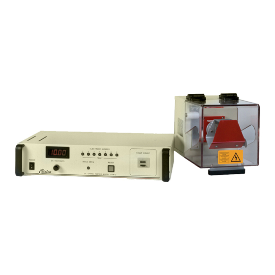
Models STM-10/20GF DC Spark Testers Introduction The.Model.STM-10GF.and.STM-.20GF.Multi-.Electrode.D.C. Spark.Testers.were.designed.to.spark.test.products.such.as.multiconductor constructions.during.bunching.and.cabling.processes. As.many.as.seven.High.Voltage.Test.Modules.may.be.connected.to.a single.control.unit. When.a.fault.is.detected.in.an.electrode,.a.light.on.the.HV.Test Module.chassis.illuminates,.and.a.signal.is.instantly.sent.to.a.corre.- sponding.channel.on.both.the.front.panel.and.the.J303.Fault.Output Connector.of .the.spark.tester..The.spark.tester.registers.the.fault.and responds.in.accordance.with.the.operating.mode.selected.for.pro.- cess.control.output..The.process.control.relay.may.latch.or.close momentarily,.activating.external.alarms,.lights.or.machinery.con.- nected.to.the.relay.contacts..High.voltage.can.remain.ON.or.shut OFF.when.a.fault.occurs. Each.HV.Test.Module.connects.directly.to.the.STM-GF.control.unit and.may.be.located.as.far.as.60.meters.(approx..200.feet).away. Page 2 - STM-10/20GF Instruction Manual... -
Page 7: Installation
The.Model.STM.DC.Spark.Tester.consists.of .a.control.unit,.as.many as.seven.high.voltage.test.modules.complete.with.electrodes,.and interconnecting.cables..Several.types.of .electrodes.are.available, such.as.bead.chains,.brushes,.and.bead/brush.combinations;.the electrodes.used.should.be.chosen.to.meet.the.requirements.of .the spark.test.application..Consult.the.factory.if .assistance.is.required in.your.selection. Select a suitable location for control unit and high voltage test module The.STM.DC.Spark.Tester.control.unit.is.designed.for.use in.a.fixed.location,.permanently.connected.to.its.power.source..The control.unit.may.be.mounted.on.a.table.or.platform,.placed.in.a.rack, mounted.on.a.Clinton.floor.stand,.or.installed.in.equipment.such.as extruders.or.rewinders..Each.high.voltage.test.module.may.be.lo.- cated.as.far.as.200.feet.(60.meters).from.the.control.unit,.providing that.the.correct.length.of .interconnecting.cable.has.been.ordered. It.is.recommended.that.the.spark.tester.control.unit.be.located.not less.than.0.6.meters.above.floor.level.and.within.easy.reach.of .the operator. To.mount.the.control.unit.on.a.horizontal.surface: Insert.(4).M6.screws.through.the.mounting.surface.and.secure.them in.the.tapped.M6.holes.in.the.bottom.of .the.spark.tester..Make.sure that.ventilation.slots.are.not.blocked.and.that.mounting.screws.are not.overtightened. -
Page 8: Wiring.requirements
Models STM-10/20GF DC Spark Testers To mount the control unit or high voltage test module on a Clinton floor stand Secure.the.stand.to.the.floor.with.M8.bolts.that.are.at.least.25.mm. long..Mount.the.equipment.as.shown.in.Drawing.FS-3..Adjust.the height.of .the.test.module.so.that.the.conductor.under.test.will.pass through.the.center.of .the.electrode.assembly. Wiring Requirements Install.an.external.disconnecting.device..Install.an.external switch.or.circuit.breaker.in.close.proximity.to.the.spark.tester.and within.easy.reach.of .the.operator..The.switch.or.circuit.breaker.must meet.the.relevant.requirements.of .IEC.947-1.and.IEC.947-3.and should.be.marked.as.the.disconnecting.device.for.the.equipment. The.rating.of .the.circuit.breaker.or.fuse.should.be.no.greater.than.5 amperes. See.Figure.1.for.requirements.of .the.cable.products.that.will.connect the.external.circuit.breaker.or.switch.to.the.power.source.and.to.the... - Page 9 Models STM-10/20GF DC Spark Testers STM-10/20GF Instruction Manual - Page 5...
- Page 10 Models STM-10/20GF DC Spark Testers With.a.screwdriver,.remove.the.aluminum.cover.on.the.right.side.of the.control.unit.back.panel.to.expose.the.11-.pin.connector.TB101. Power.lines.and.external.devices.controlled.by.the.fault.relay.will be.connected.here.as.shown.in.the.following.diagrams..The.Protec.- tive.Conductor.Terminal.is.located.just.above.the.11-pin.connector and.is.marked.with.the.symbol.shown.at.right. Thread.the.cables.and.ground.lead.through.½”.flexible.PVC.conduit (McMaster-Carr.7609K3,.CIC.part.number.03802).and.then through.the.½”.connector.in.the.aluminum.terminal.block.cover. Tighten.the.connector.to.secure.the.conduit.to.the.connector. Install mains power. Crimp. a. ring. terminal. onto. the. power. line. ground. lead.. Fasten. the. powerline. ground.lead.ring.terminal.under.the.lock.washer.and.screw.provided.on.the.Pro. tective.Conductor.Terminal..Connect.the.other.end.to.a.safety.ground.system.in. accordance.with.EN.60204-1:1993,.Section.5.2,.Ta.ble.1..Secure.the.remaining. conductors.in.the.11-.pin.connector.as.shown.below.in.Figure.2: Page 6 - STM-10/20GF Instruction Manual...
- Page 11 Models STM-10/20GF DC Spark Testers Connect.external.devices.to.be.controlled.by.the.fault.relay.as. follows.in.Figure.3: STM-10/20GF Instruction Manual - Page 7...
- Page 12 Models STM-10/20GF DC Spark Testers To.reset.the.spark.tester.relay.from.a.remote.location,.encase.the shield.of .a.single.conductor.cable.in.tubing.and.connect.to.terminal 6.(G);.wire.the.conductor.to.terminal.7.(RESET)..Connect.the.other ends.of .the.cable.to.a.Normally.Open.switch..Cables.and.switches used.must.be.rated.according.to.Figure.1..If .the.remote.feature.is.not desired,.leave.terminal.7.(RESET).empty. To.turn.OFF.spark.tester.high.voltage.from.a.remote.location,.re.- move.the.factory-.installed.jumper.between.terminals.5.&.6.(HV OFF.and.G)..Encase.the.shield.of .a.single.conductor.cable.in.tubing and.connect.to.terminal.6.(G)..Connect.the.conductor.to.terminal.5 (HV.OFF)..Wire.the.other.ends.of .the.cable.to.a.Normally.Closed.re.- lay.or.switch..Cable,.switches.and.relays.used.must.be.rated.accord.- ing.to.Figure.1..If .you.do.not.desire.to.turn.OFF.HV.from.a.remote location.do.not.remove.the.factory-installed.jumper.between.termi.- nals.5.&.6. To.perform.both.of .the.above.functions:.Use.a.two.conductor shielded.cable.as.in.Figure.4.be.low..Enclose.the.shield.in.tubing.bef .- ore.connecting.to.terminal.6.(G). Connect.each.high.voltage.test.module.to.the.STM-.GF.control unit..Using.a.9-.pin.D-.sub.connecting.cable.supplied.with.the equipment,.connect.each.HV.test.module.to.a.channel.on.the.rear.of the.STM-.GF.control.unit. Page 8 - STM-10/20GF Instruction Manual...
-
Page 13: Set.dip.switch.sw1
Models STM-10/20GF DC Spark Testers Set DIP Switch SW1 Locate.10-.pin.DIP.Switch.SW1.in.the.middle.of .the.back.panel.of the.control.unit. Determine.whether.the.process.control.relay.is.to.latch.or.reset automatically.after.a.fault..Terminals.2.and.3.(COM.and.NC).of TB101.are.normally.connected.by.internal.relay.contacts..When.the spark.tester.is.in.LATCH.mode,.a.fault.in.the.electrode.will.cause the.relay.to.activate,.open.ing.terminals.2.and.3.(COM.and.NC).and connecting.terminals.1and.2.(NO.and.COM)..External.alarms, lights.or.machinery.connected.to.these.relay.contacts.will.be.acti.- vated.until.the.spark.tester.is.reset..Set.position.SW1-9.to.ON.if LATCH.mode.is.desired. When.the.spark.tester.is.in.NON-.LATCH.mode,.the.relay.contacts will.close.only.momentarily,.for.the.Process.Control.Duration.or.for the.length.of .the.fault,.which.ever.is.longer..(See.below.to.set.the Process.Control.Duration.).Set.position.SW1-9.to.OFF.for.NONLATCH mode. Set.the.Process.Control.Duration..The.Process.Control.Duration begins.when.a.fault.is.detected.in.the.electrode..It.determines.the length.of .time.the.fault.relay.contacts.will.remain.closed.after.a fault. If .the.spark.tester.is.in.LATCH.mode.(SW1-9.is.ON),.set.the.Process Control.Duration.to.50.ms.,.since.the.spark.tester.can.be.reset.only after.the.Process.Control.Duration.elapses. When.the.spark.tester.is.in.NON-.LATCH.mode.(SW1-9.is.OFF), the.Process.Control.Duration.may.be.set.for.lengths.from.12.5.ms. to.2.½.seconds..Many.alarms.and.lights.require.a.signal.of .at.least one.second.before.responding;.the.fault.contact.closure.time.should be. - Page 14 Models STM-10/20GF DC Spark Testers The.primary.duration.settings.are.given.in.Figure.6..To.set.a.Process Control.Duration.which.does.not.correspond.to.the.primary.value, calculate.the.reciprocal.of .the.desired.duration,.and.then.determine which.positions.must.be.turned.ON.to.match.the.reciprocal.value. For.example,.if .the.desired.Process.Control.Duration.is.0.60 seconds.,.its.reciprocal.is.1.67sec-1..For.the.closest.setting,.put.posi.- tions.#2.and.#4.ON,.as.they.together.yield.a.reciprocal.of .1.67.sec.-1 or.a.duration.of .0.60.seconds. Determine.whether.the.high.voltage.in.the.test.module.is.to.remain ON.after.a.fault.is.discovered..When.position.SW1-10.is.OFF, high.voltage.will.remain.ON,.even.after.a.fault.is.found..This condition.is.called.Continuous.High.Voltage.Mode. Page 10 - STM-10/20GF Instruction Manual...
-
Page 15: Prepare.your.product
In sure that the product to be tested is dry as it enters the spark test electrode. The.combination.of .water.and.spark.testing.is.not.a.desirable.one..A.continu.ous. film.or.sheath.of .water.on.the.product.can.provide.an.effective.electrical.path.to. the.nearest.grounded.point..Surface.leakage.can.trigger.a.false.count.in.the.spark. tester..Efficient.air.wipes.that.can.adequately.dry.the.product.before.it.enters.the. electrode.are.available.from.Clinton. Ground the product conductor(s). This.is.a.safety.precaution.as.well.as.a.requirement.of .DC.spark.test.specifica. tions. Center the product in the entrance of the safety guard. Be.sure.it.will.remain.centered.as.it.is.being.drawn.through.the.electrode.as.- sembly..Lateral.wire.vibration.which.may.be.imperceptible.can.cause.phantom. -
Page 16: Operation
Operation Caution..Before.operating.the.spark.tester,.familiarize.yourself .with.the.controls. and.features.of .the.unit..Review.all.safety.warnings.and.observe.operating.proce- dures..Locate.the.external.disconnecting.device.to.which.the.spark.tester.is.con- nected.and.know.how.to.operate.it..If .this.equipment.is.not.used.in.the.manner. specified,.protection.provided.by.the.equipment.may.be.impaired. Front Panel Controls 1.. On/off .power.switch..This.switch.controls.all.power.to.the.spark.tester. control.unit.and.high.voltage.test.module. 2.. Voltage. adjustment. control.. The. Model. STM-10GF. voltage. range. is. 0-10,000.volts.DC;.the.Model.STM-20GF.has.a.range.of .0-20,000.volts. DC..Spark.test.voltage.is.adjusted.by.turning.the.knob.beneath.the.digi- tal.voltmeter.clockwise..However,.each.type.of .electrode.demands.a.mini. mum.test.voltage.for.effective.fault.detection..Consult.the.factory.if .assis. tance.is.required.in.determining.the.voltage.range.for.the.electrode.in.use.. 3.. Digital.voltmeter..When.the.output.voltage.has.been.adjusted.to.1.00.KV,. the.STM-GF.digital.voltmeter.will.read.1.00.kilo.volts..A.test.voltage.of . 10KV.will.be.expressed.at.10.00;.a.setting.of .1500.volts.will.read.1.50. -
Page 17: High.voltage.test.module
.this.HV.Test.Module,.the.fault.light.will.illuminate. NOTE: An ST- 10G01 High Voltage Test Module is ST- 20G01 High to.be.used.with.the.STM-10GF.control.unit;.an. Voltage Test Module must be used with an STM-20GF control unit. High Voltage Test Modules are NOT inter- changeable. STM-10/20GF Instruction Manual - Page 13... -
Page 18: Testing.your.product
Models STM-10/20GF DC Spark Testers Testing Your Product Caution.. During. installation,. the. STM-GF. Spark. Tester. was. programmed. to. report.and.respond.to.faults.in.specific.ways..Wiring.and.DIP.switch settings.must.not.be.changed.except.by.qualified.personnel. 1.. Be.sure.the.product.conductor(s).are.grounded..If .this.is.not.the.case,.do. not.proceed..Contact.service.personnel.to.review.the.spark.tester.instal- lation. 2.. If .a.bead.chain.electrode.has.been.selected,.be.sure.that.the.product.runs. through.the.upper.half .of .the.beads..If .a.brush.electrode.is.used,.check. that.the.wire.runs.through.the.center. 3.. Turn.ON.the.external.disconnecting.device.to.bring.power.to.the.spark. tester. 4.. Turn. the. voltage. adjustment. control. fully. counterclockwise.. Turn. the. spark.tester.power.switch.ON..Push.the.front.panel.RESET.button.and. -
Page 19: Modes Of Operation
Models STM-10/20GF DC Spark Testers Modes of Operation The spark tester will operate in accordance with the DIP switch settings selected during “Installation.” •. Continuous.High.Voltage.Latch.Operation.(DIP.Switch.SW1-8 ON,.SW1-9.ON,.SW1-.10.OFF):.When.a.single.fault.is.detected in.any.of .the.HV.Test.Modules,.the.counter.will.advance.by.one, the.relay.will.latch,.the.voltage.will.stay.ON,.the.HV.Test.Mod.- ule.fault.light.and.the.corresponding.fault.light.on.the.control unit.will.illuminate..Auxiliary.devices.wired.between.relay.ter.- minals.COM.(Pin.number.2.of .TB101).and.either.NC.(.Pin.3).or NO.(Pin.1).will.be.activated.until.the.spark.tester.is.reset..To.re.- set.the.spark.tester.relay.and.fault.light,.press.the.front.panel.RE.- SET.button.or.reset.by.a.remote.switch.wired.between.relay terminals.RESET.and.G..Press.the.black.button.on.the.counter.to reset.the.fault.count.to.zero. •. Remove.High.Voltage.Latch.Operation.(SW1-8.ON,.SW1-2 ON,.SW1-.10.ON):.When.a.single.fault.is.detected.in.any.of .the HV.Test.Modules,.the.relay.will.latch.and.the.voltage.will.go OFF..Auxiliary.devices.wired.between.relay.terminals.COM... -
Page 20: J303.Subminiature.connector.pin.functions
Models STM-10/20GF DC Spark Testers J303 Subminiature Connector Pin Functions Figure 9. J303 The.Model.STM-GF.Spark.Tester.provides.an.optoisolated.fault output.for.each.channel.located.at.the.J303.15-pin.D.subminiature connector.situated.on.the.rear.panel.of .the.control.unit..The connecting.cable.is.not.supplied.by.Clinton.Instrument.Company. The.cable.composition.is.normally.dictated.by.the.PLC.or computer,.but.ordinarily.22.gauge.conductors.(individually shielded.or.shielded.as.pairs).are.required..The.maximum.length.of the.cable.is.also.determined.by.the.equipment.to.which.you.are connecting..However,.it.is.recommended.that.the.cable.length.not exceed.10.meters. When.control.unit.is.first.turned.on.or.when.high.voltage.is.first.en.- abled.using.remote.HV.on.terminal,.the.fault.light.will.illuminate, and.the.fault.output.transistor.will.conduct.for.400ms.on.each.chan.- nel.which.has.an.electrode. Each.fault.output.transistor.is.normally.in.the.non-conducting.state. When.a.fault.occurs.at.one.of .the.electrodes.the.corresponding.fault transistor.will.conduct.until.reset. Page 16 - STM-10/20GF Instruction Manual... - Page 21 Models STM-10/20GF DC Spark Testers STM-10/20GF Instruction Manual - Page 17...
-
Page 22: Troubleshooting
Models STM-10/20GF DC Spark Testers Troubleshooting Caution..Troubleshooting.is.to.be.performed.by.qualified.personnel.only..Failure.to. follow.the.procedures.in.this.manual.may.result.in.danger.to.personnel.and.equip- ment.damage. Faults are not being detected. (1).Check.to.be.sure.your.product.is.grounded. (2).The.test.voltage.may.be.too.low,.or.you.may.need.a.different type.of .electrode..Faults.can.not.be.indicated.unless.an.arc.oc.- curs..Consult.factory.on.your.application. Phantom faults are indicated. Lateral.wire.line.vibration.or.water.may.be.present..See.“Installation”.for.informa- tion.on.drying,.centering.and.restraining.the.product.in.the.electrode. There is no voltage indicated at the front panel or in the elec- trode. (1).Be.sure.the.clear.protective.cover.on.the.electrode.is.properly closed.and.that.the.OPEN.INTLK.light.is.not.illuminated. -
Page 23: Maintenance
Models STM-10/20GF DC Spark Testers Maintenance Caution..The.maintenance.procedures.listed.below.are.to.be.performed.by.qualified. service.personnel.only..Failure.to.follow.these.procedures.may.result.in.danger.to. personnel.and.equipment.damage. Fuses The.fuses.in.this.equipment.are.not.expected.to.fail.in.normal.operation..Their.failure. may.be.an.indication.of .equipment.malfunction.requiring.qualified.repair.personnel. ·.Fuse.F101.is.the.powerline.fuse..Use.1.Amp.250VAC.5x20mm low.breaking.quick.acting.fuse.CIC.part.number.90175. ·.Fuse.F102.is.the.process.control.fuse..Use.2.Amp.250VAC 5x20mm.low.breaking.time.delay.fuse.CIC.part.number.02606. The.fuses.are.found.on.the.back.of .the.control.unit,.on.either.side.of the.aluminum.cover.which.protects.the.11-pin.connector..To. change.the.fuses:.turn.power.to.the.machine.OFF.by.turning.OFF the.external.disconnecting.device..Using.a.flat.head.screwdriver, turn.the.fuse.holder.cover.½.turn.counter-.clockwise.and.gently.pull the.fuse.holder.out.until.the.fuse.is.exposed..Replace.the.fuse,.push the.fuse.holder.back.into.the.con.trol.unit,.and.with.the.screw.driver, turn.the.fuse.holder.cover.½.turn.clockwise.to.lock.into.place. Periodic Inspection It.is.important.to.inspect.the.High.Voltage.Test.Modules.periodically.for.residue.and. wear. Insulation.and.water.deposits.can.reduce.the.effectiveness.of .the spark.test..The.red.electrode.mounting.plate.may.be.wiped.with.a clean,.dry.cloth..Bead.chain.assemblies.contaminated.with.insula.- tion.residue.should.be.removed.from.the.high.voltage.test.module and.sand.blasted. Broken.safety.covers.and.mounting.plates.and.electrode.assemblies with.worn.brushes.or.missing.beads.should.be.replaced.immediately. Refer.to.the.“Troubleshooting”.section.for.assistance.with.electrical problems. STM-10/20GF Instruction Manual - Page 19... -
Page 24: Calibration
.the.nee.- dle.in.the.mirror.is.directly.behind.the.needle.itself,.and.observe.the needle.position.on.the.scale..This.eliminates.any.parallax.error.that might.result.from.viewing.the.meter.at.a.slight.angle. Voltage Calibration 1.. With.the.power.to.the.spark.tester.OFF,.connect.the.HV.lead.from.the.EVM. to.the.electrode.of .a.High.Voltage.Test.Module..Connect.the.ground.termi- nal.of .the.EVM.to.equipment.ground..Zero.the.EVM. 2.. If .calibrating.an.STM-10GF:.Set.the.EVM.range.switch.to.the.10KV.range.. Turn.the.STM-10GF.control.unit.ON;.turn.the.voltage.control.on.the.STM-. 10GF. until. the. EVM. reads. 10KV.. If . calibrating. an. STM-. 20GF:. . Set. the. EVM.range.switch.to.the.20KV.range..Turn.the.STM-.20G.control.unit.ON;. turn.the.voltage.control.on.the.STM-.20G.until.the.EVM.reads.20KV. 3.. Observe.the.STM-G.front.panel.meter.indication..Record.the.reading. 4.. Following.recognized.calibration.procedures,.adjust.the.STM-G.volt.age.so. that.the.EVM.reads.each.cardinal.point.on.the.STM-G.panel.meter.(1KV,. 2KV,. 3KV,. etc.);. record. the. STM-G. panel. meter. reading. at. each. of . these. -
Page 25: Voltage.calibration
Models STM-10/20GF DC Spark Testers 0-10V Control Voltage Calibration 8.. Locate.the.main.printed.circuit.board.at.the.back.of .the.control.unit,.marked. part.number.90195..With.the.STM-G.power.turned.OFF,.connect.a.digi- tal.voltmeter.(DVM).with.a.10-megohm.or.higher.impedance.from.GND. (Test.Point.TP4).to.Pin.2.of .U2. 9.. Turn.ON.the.STM-10GF.and.adjust.the.voltage.until.the.DVM.reads.10v. (9.5v.for.the.STM-.20G). 10..Locate.minipot.R20.on.the.main.PC.board.and.adjust.until.theSTM-10GF. panel.meter.reads.“10.00”.(”19.00”.on.the.STM-20G). 11...Turn.OFF.the.STM-G.and.disconnect.the.DVM. HV Test Module Calibration 12..Con.nect.the.EVM.to.the.HV.Test.Mod.ule.that.was.out.of .tol.er.ance.and. ad.just.the.STM-.10GF.volt.age.to.10.00.or10KV.(19.00.or.19KV.on.the. STM-.20G). 13..Re.fer.to.Fig.ure.10..In.sert.a.small.screw.driver.through.the.lower.hole.in. the.rear.of .the.ST-10G01.HV.Test.Mod.ule.as.shown..Two.minipots.can.be. seen.through.the.lower.hole..Ad.just.the.bot.tom.minipot.R206.un.til.the. STM-10G.reads.10KV.(ad.just.STM-20G.with.ST-20G01.to.19KV.) 14..Reduce.the.spark.tester.control.unit.voltage.control.until.the.STM-G.front. panel.meter.reads.1KV..Insert.a.small.screwdriver.through.the.back.hole.as. shown.to.adjust.mini.pot.R201. 15..Repeat.steps.13.to.14.until.no.further.adjustment.is.required. 16..Repeat.the.HV.Test.Module.Calibration.(steps.12.through.15).for.all.HV. -
Page 26: Replacement.parts
Part Number Description 90175 1 amp 250V fuse 02606 2 amp 250v fuse 15095 Filter PC Board 90195 Main PC Board for STM-10GF and STM-20G 01401 Counter 24V 01408 Digital Voltmeter w/bezel 03018 Power Switch 07193 Clear cover for HVTM... -
Page 27: Technical.specifications
Models STM-10/20GF DC Spark Testers Technical Specifications Control Unit: Model STM-10GF or STM-20GF DC Spark Tester Con- trol Unit. High Voltage Test Modules: ST- 10G01 or ST-20G01 Bead Chain, 25mm (1”) max product diameter,50mm (2”) wireline. Consult factory for other choices. -
Page 28: Warranty
Models STM-10/20GF DC Spark Testers Warranty The.information.contained.in.this.document.is.subject.to.change without.notice..The.Clinton.Instrument.Company.makes.no.war.- ranty.of .any.kind.with.regard.to.this.material,.including,.but.not.lim.- ited.to,.the.implied.warranties.or.merchantibility.and.fitness.for.a particular.purpose. The.Clinton.Instrument.Company.shall.not.be.liable.for.errors.con.- tained.herein.or.for.incidental.damages.in.connection.with.the.furnishing,. performance,.or.use.of .this.material. We.warrant.to.the.original.purchaser.that.the.equipment.described herein.is.free.from.defects.in.materials.and.workmanship.for.a.peri.- od.of .one.year.from.the.date.of .invoice,.our.obligation.under.this warranty.being.limited.to.repair.or.replacement.of .the.defective parts..This.warranty.does.not.apply.to.fuses,.lamps,.or.any.normally. expendable.parts..Any.part.appearing.to.have.defects.in.material.or. workmanship,.upon.our.examination.only.and.as.determined.by.us,.and. providing.the.equipment.has.not.been.subject.to.abuse,.misuse,.or.alteration,. will.be.repaired.or.replaced.at.no.charge.for.materials.and.labor,.either.upon. receipt.of .the.defective.part.or.equipment,.transportation.charges.prepaid,.at. our.plant.or.at.the.equipment.location,.as.selected.by.us..No.parts.or.equipment shall.be.returned.without.our.prior.permission..Any.parts.replaced under.this.warranty.shall.be.warranted.until.the.expiration.date.of the.original.warranty. The.warranties.herein.are.in.lieu.of .all.other.warranties,.expressed or.implied,.and.of .all.other.obligations.or.liabilities.on.our.part.con.- cerning.this.equipment. Page 24 - STM-10/20GF Instruction Manual... - Page 30 MEASURING & TESTING clinton instrument company Grounding of conductors during the spark test by Henry Clinton early all industry-wide specifications for insulated wire with the con duc tor or with a flawed insu la tion area any where along and cable pertaining to in-line spark testing require the grounding the wire line, C can dis charge through his body to ground.
- Page 31 When are fol lowed. an insu la tion flaw passes through the elec trode, cur rent drawn Henry Clinton is president of Clinton Instrument Co., from the spark tester increases sharply in this same ratio, sub ject to Clinton, CT.
Need help?
Do you have a question about the STM-10GF and is the answer not in the manual?
Questions and answers