Advertisement
Quick Links
PRODUCT INSTRUCTION
PROMAX 3
(Basic Set Up Guide)
Stock Code
00160
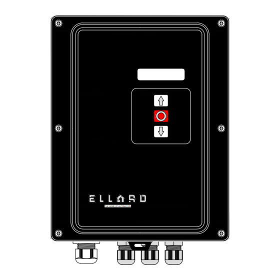
PROMAX 3 - Main Control Panel
Description
THE HOME OF AUTOMATION
Roundthorn Industrial Estate
Floats Road, Wythenshawe
Manchester, M23 9WB
Tel: +44 (0)161 - 945 - 4561
sales@ellard .co.uk
technical@ellard.co.uk
Doc No
PI - PROMAX 3
Iss
1
Date
11-05-2021
Advertisement

Related Manuals for Ellard PROMAX 3

Summary of Contents for Ellard PROMAX 3
- Page 1 Manchester, M23 9WB PROMAX 3 Tel: +44 (0)161 - 945 - 4561 sales@ellard .co.uk (Basic Set Up Guide) technical@ellard.co.uk Description Stock Code Doc No PI - PROMAX 3 00160 PROMAX 3 - Main Control Panel Date 11-05-2021 THE HOME OF AUTOMATION...
- Page 2 PROMAX 3 - Contents 1) Safety Instructions 2) General 3) Technical data 4) Board layout 5) Power supply and motor connections 5.1 230v 1ph - 3 wire motor 5.2 230v 1ph - 4 wire motor 5.3 415v 1ph - 3 wire motor Limit switches - connection and set up 6.1 Mechanical limit switch...
- Page 3 Safety instructions This equipment or any electrical work should be carried out by a suitable trained or competent person Disconnect and isolate the power supply before continuing any electrical work Before installing the panel, check the door is in good mechanical working condition, balanced and opens and closes correctly using the manual haul chain Install the control unit adjacent to the door, at minimum height of 1.5m...
- Page 4 General A versatile control panel with mechanical or digital limit position control for KOSTAL or Elektromaten encoders Fitted with power supply outputs of 24vac and 24vdc (max load of 700mA) for ancillary devices such as photocells, safety edge, radar, wireless safety edge and traffic lights Front cover push buttons with LED indication Inputs for switching devices including open and close buttons, partial...
- Page 5 Technical data...cont THE HOME OF AUTOMATION Cable gland Drop in 3 x M16 Cable gland 3 x M16...
-
Page 6: Board Layout
Board layout REMOTE RBAND CONTROL ANT. EXPANSION 1 RBAND EXPANSION 2 T.CLOSE AUTO-CLOSE DM.OPEN SEL.VIN DM.CLOSE NO PRE-FLASH PRE-FLASH BREAK NO BREAK NO STOP OPENING CLOSE BY SEC.CL TEST OPEN TEST CLOSE FINE ADJUSTMENT LIMIT SWITCH ENCODER.ABS PROGRAMMING OPEN PROG (OUT 19) SEC.OP CLOSE... - Page 7 Board layout...cont Expansion Slot 1 - For RSEC3 receiver card Expansion Slot 2 - For Traffic Light Card Radio Receiver Connector Output: 24v AC for accessories (see note) Fuse F1A/250v Voltage Selector 230v AC / 400v AC Power Supply In Power On LED / Error LED indicator Travel Direction LED indicator 10.
- Page 9 6.1 Mechanical limit switch MECHANICAL LIMIT SWITCH MECHANICAL LIMIT SWITCH SET UP 1. Move DIP Sw and select LIMIT SWITCH (IN 8) "Limit Switch" THERMAL H/CHAIN STOP (IN 3) 2. Move DIP Sw and select DM.OPEN "DM open" and "DM close" DM.CLOSE SAFETY LIMIT 3.
- Page 10 7.1 Pneumatic air pressure switch PROGRAMMING A SAFETY EDGE FOR MOTORS WITH MECHANICAL LIMITS Activation - Stops and fully re-opens a closing door EDGE (IN 8) 1. Connect safety device to (IN 3) be used as per diagram(s) opposite 2. Move DIP Sw and select DM.CLOSE "DM close"...
- Page 11 8.1 Low level - Reflective type LOW LEVEL (CLOSING) PHOTOCELL Activation - Stops and fully re-opens a closing door (OUT 19) The PROMAX can be configured to produce a test signal to check the integrity of the photocell relay contact before any Reflector movement in the close direction This test opens and closes the photocell contact...
-
Page 12: Output Relays
9.1 External push button 9.3 Output relays NORMAL (OFF) (IN 8) ACTIVATED (ON) STOP STOP (IN 3) COMMON (IN 7) OPENED CLOSED FLASH M.BRAKE OPEN OPEN 230V 230V CLOSE CLOSE Opened status: NORMAL (OFF) ACTIVATED (ON) The opened status output is a volt free signal, this signal is a normally open state until the top limit position is reached where upon the relay will close to produce an output... - Page 13 10. DIP Sw - Features and functions AUTO-CLOSE DM.OPEN DM.CLOSE NO PRE-FLASH PRE-FLASH BREAK NO BREAK NO STOP OPENING CLOSE BY SEC.CL TEST OPEN TEST CLOSE FINE ADJUSTMENT LIMIT SWITCH ENCODER.ABS Dip Switch Door closes using the Auto-close function AUTO-CLOSE No Auto-close function active Door runs continuous to the open position DM.OPEN...
-
Page 14: Troubleshooting
11. Trouble shooting LED Indication - Membrane buttons Status Indication Solution On continuously Power Available ---- Check and remove any obstruction 1 flash every 3 sec's Radio band / safety edge activated Check the safety device connection Check and remove any obstruction 2 flashes every 3 sec's Close photocell activated Check link fitted, if no photocell used...
Need help?
Do you have a question about the PROMAX 3 and is the answer not in the manual?
Questions and answers
Wiring diagram for fitting radars