Table of Contents
Advertisement
Advertisement
Table of Contents

Related Manuals for Redarc BCDC1240D


Summary of Contents for Redarc BCDC1240D
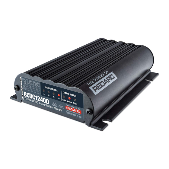
- Page 1 Dual Input Multi-stage 12V In-vehicle Battery Charger BCDC1225D, BCDC1240D...
-
Page 2: Warnings And Safety Instructions
Battery Charger. 2. Do NOT alter or disassemble the Battery Charger under any circumstances. All faulty units must be returned to REDARC for repair. Incorrect handling or reassembly may result in a risk of electric shock or fire and may void the unit warranty. -
Page 3: Table Of Contents
SPECIFICATIONS Part Number BCDC1225D BCDC1240D Continuous Current Rating Vehicle Input Fuse Rating 40A (Not Supplied) 60A (Not supplied) REDARC FK40 recommended REDARC FK60 recommended Output Fuse Rating Output Power 375W 600W Vehicle Input Voltage Range 9-32V Solar Input Voltage Range... -
Page 4: Product Function
12V or 24V and an unregulated 12V nominal solar panel input. The input voltage of the BCDC1225D/BCDC1240D can be above, below or equal to the output voltage making it ideal for charging an auxiliary 12V battery where the distance from the main battery may cause a significant voltage drop. -
Page 5: Charge Profile Leds
PRODUCT FUNCTION Charge Status LEDs The Charge Status LEDs indicate to the user which inputs are available and what stage of the charge process the unit is currently in. 1.3.1 Solar & Vehicle LEDs The Solar and Vehicle LEDs will be ON when the input is available and in use and OFF when the input is not available or not in use. -
Page 6: Optional External Led
PRODUCT FUNCTION 1.3.3 Optional External LED To provide charge status and error feedback away from the main unit, a basic 3V LED can be wired as show in Figures 2.7.1 and 2.7.2. If used, this external LED is either OFF (BCDC not charging), ON (BCDC charging) or FLASHING (see error codes in Section 1.5 Error Codes). -
Page 7: Turn On/Off Thresholds
PRODUCT FUNCTION Turn On/Off Thresholds Input 12V Vehicle Input 24V Vehicle Input Solar Input Trigger Standard Standard Settings Voltage Voltage Input Turn ON 13.2V 12.0V 26.4V 24.0V 9.0V ABOVE Open Circuit Low voltage conditions Turn OFF 12.7V 11.9V 25.4V 23.8V 9.0V BELOW Input... -
Page 8: Battery Test Mode
PRODUCT FUNCTION Battery Test Mode The unit features a battery test mode which occurs every 100 seconds. The test mode is designed to both test that the input conditions are still met and check for the presence of a battery on the output of the unit. This feature is designed to protect the vehicle battery from over discharge and protect the vehicle and wiring in the event of damage to the output connection. -
Page 9: Charge Profile Selection (Orange Wire)
INSTALLATION Charge Profile Selection (ORANGE Wire) The ORANGE wire is used to select the Maximum output voltage. This is achieved by connecting in the following way: To select Profile A leave the ORANGE wire disconnected. This will set the Maximum voltage to 14.6V. To select Profile B connect the ORANGE wire to Common Ground. -
Page 10: Input Trigger Settings (Blue Wire)
16 - 30 13.56 1 - 5 3 - 16 13.56 BCDC1240D 5 - 9 16 - 30 20.28 Cable and fuse sizes are specified by various codes and standards which depend on the type of vehicle the Battery Charger is installed into. Selecting the wrong cable or fuse size could result in harm to the installer or user and/or damage to the Battery Charger or other equipment installed in the system. -
Page 11: Wiring
INSTALLATION Wiring The heavy gauge wires on the BCDC1225D and BCDC1240D unit carry peak currents of up to 35 and 50 Amps respectively, and it is important to make a good, low resistance, electrical connection that will not degrade over time. Failure to make a good, reliable contact may result in breakdown of the wire insulation and cause a short circuit, or worst case a fire. -
Page 12: Typical Setup
Auxiliary be connected to chassis Battery earth. *Fuse Ratings as per table on Page 2 Figure 2.7.1 - Typical Lead Acid type Setup NOTE: BCDC1225D/BCDC1240D will only accept input from an unregulated solar panel. SOLAR Optional LED INPUT INPUT INPUT... -
Page 13: Troubleshooting
TROUBLESHOOTING There are no LEDs ON at all… This indicates that there is no battery connected to the output (BROWN wire) or that battery is not at a suitable voltage level to be charged AND the input (YELLOW/RED wire) of the charger is not connected. 1. -
Page 14: Frequently Asked Questions
The unit is also microprocessor controlled allowing it to output a Redarc proprietary charging algorithm independent of the input. This allows the unit to charge specific to the battery type even if the input voltage is low due to voltage drop. -
Page 15: Two Year Warranty
Australian Consumer Law. Redarc Electronics Pty Ltd atf the Redarc Trust trading as Redarc Electronics (“Redarc”) offers a warranty in respect of its Products where the Products are purchased from an authorised distributor or reseller of Redarc by a person (“Purchaser”), on the terms and conditions, and for the duration, outlined below in this document (“Warranty”). - Page 16 For specific USA +1 (704) 247-5150 Warranty terms Canada please visit... +1 (604) 260-5512 Mexico www.redarcelectronics.com +52 (558) 526-2898 UK/Europe power@redarcelectronics.eu www.redarcelectronics.eu +44 (0)20 3930 8109 Copyright © 2019 REDARC Electronics Pty Ltd. All rights reserved. www.redarc.com.au WARBCDCD - REV9...
Need help?
Do you have a question about the BCDC1240D and is the answer not in the manual?
Questions and answers