
Related Manuals for FMS FMS137


Summary of Contents for FMS FMS137
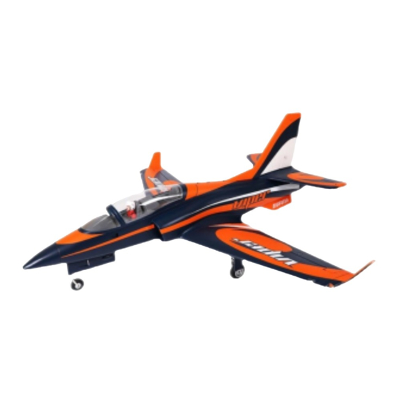
- Page 1 90mm Viper Instruction Manual 操作手册 FMSMODEL.COM REALISTIC RIGID STABLE Retract & Flaps Installed Strong durable EPO Smooth flying performance...
- Page 3 WARNING WARNING: Read the ENTIRE instruction manual to become familiar with the features of the product before operating. Failure to operate the product correctly can result in damage to the product,personal property and cause serious injury. This is a sophisticated hobby product and NOT a toy. It must be operated with caution and common sense and failure to do so could result in injury or damage to the product or other property.
-
Page 4: Kit Contents
Introduction The FMS 90mm Viper is an upgrade from the best-selling 70mm No matter whether you have collected Vipers before, this newly Viper, designed to provide the look and performance of a jet launched FMS 90mm Viper EDF is very worth looking forward fighter with the stability of a low-wing sport aircraft, so that more to. -
Page 5: Model Assembly
Model assembly Horizontal stabilizer installation 1.Attach the horizontal stabilizer to the fuselage as shown. 2.Insert the included two screws (HKM 3.0*10) into the circular aluminum part. Do not lock the screws. And then put the aluminum part into the slot shown in the figure. 3.Lock the horizontal stabilizer to fuselage by tightening the screws on the circular aluminum part. -
Page 6: Main Wing Installation
Model assembly Main wing installation 1.Slide the wing spars into the fuselage as shown. 2.Install the left and right wing halves over the wing spars and into the wing slots. Be sure the connectors on both sides are attached precisely and firmly. 3.Secure the left and right wings to the fuselage using four screws included (HKM 3.0*10) 4.Attach the winglet to the corresponding slot on main wing, then slide toward the rear of the fuselage to lock in place. -
Page 7: Battery Installation
Battery installation 1.Pull back on the latch and remove the battery hatch. 2.Apply the hook tape to the cable end of the battery. 3.Slide the full charged battery into the battery compartment with the power supply cable toward the rear end of the plane. Note: The center of gravity can be adjusted by moving the battery forward or aft.Having the correct center of gravity is critical to achieving proper flight characteristics. -
Page 8: Control Throws
Transmitter and model setup Before getting started, bind your receiver with your transmitter. Bank left Please refer to your transmitter manual for proper operation. CAUTION: To prevent personal injury, DO NOT install the propeller assembly onto the motor shaft while testing the control surfaces. -
Page 9: Clevis Installation
Clevis installation 1.Pull the tube from the clevis to the linkage. 2.Carefully spread the clevis, then insert the clevis pin into the desired hole in the control horn. 3.Move the tube to hold the clevis on the control horn. Control horn and servo arm settings More control throw Horns Arms... -
Page 10: Before Flying The Model
Before flying the model Flying course Find a suitable flying site Take off While applying power, slowly steer to keep the model straight. Find a flying site clear of buildings, trees, power lines and The model should accelerate quickly. As the model gains flight other obstructions. -
Page 11: Troubleshooting
Trouble shooting Problem Possible Cause Solution Aircraft will not respond to -Lower throttle stick and throttle trim to lowest settings. -ESC is not armed. the throttlebut responds to -Reverse throttle channel on transmitter. -Throttle channel is reversed. other controls. -Damaged spinner, propeller, -Replace damaged parts. - Page 12 User Manual of Brushless Speed Controller Thanks for purchasing our Electronic Speed Controller (ESC). High power system for RC model is very dangerous, please read this manual carefully. In that we have no control over the correct use, installation, application, or maintenance of our products,no liability shall be assumed nor accepted for any damages, losses or costs resulting from the use of the product.
-
Page 13: Protection Function
User Manual of Brushless Speed Controller Begin To Use Your New ESC IMPORTANT! Because different transmitter has different throttle range, please calibrate throttle range before flying. Throttle range setting (Throttle range should be reset whenever a new transmitter is being used) 1.Switch on the transmi t ter, move throttle stick to the top position. - Page 14 Program the ESC with your transmitter (4 Steps) Note: Please make sure the throttle curve is set to 0 when the throttle stick is at bottom position and 100% for the top position. NO.1 Enter program mode 1.Switch on transmitter, move throttle stick to top position, connect the battery pack to ESC 2.Wait for 2 seconds, the motor should emit special tone like "beep-beep-"...
- Page 15 警告 警告: 在组装、 调整及飞行前请务必认真阅读产品说明书以熟知产品的特性。 请严格按照说明书提示进行飞机的组 装、 调整及飞行。 如操作不当会造成产品本身损坏及其它财产损失, 甚至造成严重的人身伤害。 声明: 模型不是玩具, 具有一定的危险性, 操作者需要具备一定的飞行经验, 初学者请在专业人士指导下操作。 禁止十四岁以下儿童操作、 飞行。 安全须知 本产品飞行由无线电遥控器控制, 在飞行过程中可能会受到外界强信号源干扰而导致失控, 甚至坠机。 因此, 在飞行 过程中务必始终与飞机保持一定的安全距离, 避免意外碰撞、 受伤。 请勿在发射器电池低电量的情况下操纵模型飞机。 请勿在公路、 人群、 高压线密集区、 机场附近及其它法律法规明确禁止飞行的场合飞行。 请勿在雷雨、 大风、 大雪或者其它恶劣气象环境下飞行。 请严格遵照产品指导说明及安全警告操作本产品及其相关配置 (例如充电器、 电池等) 。 请勿将相关化工类产品、 零部件、 电子部件等置于儿童可触及的范围。 请勿将电子件暴漏于潮湿的环境中,...
- Page 16 产品特点 FMS 90mm EDF毒蛇由当下畅销的70mm EDF毒蛇升级而来,旨 特征: 在提供战斗机的外观和性能以及低翼运动飞机的稳定性,以使更 ・ 电子配置:高品质120A电调,高动力内转3670 KV1950电 多的飞行员可以享受驾驶涵道机的乐趣。 机,高效率90mm 12叶涵道组,高精度金属数码舵机。 ・ 极宽的性能范围和速度范围,可进行运动休闲飞行和特技飞 90mm EDF毒蛇单其“90mm”级别就足以振奋人心。FMS 高效 行,整体起飞、飞行和降落过程轻松流畅。 率90mm 12叶涵道组、高动力内转 3670 - KV1950 电机和高品质 ・ 带过流保护的堵转模式电子收放和CNC加工跪形结构金属起 120A电调的搭配组合,给整架飞机提供无与伦比的性能,油门 落架,有效抵抗暴力降落。 几乎瞬间相应,声浪极具临场感,搭配6S 22.2V 5000 6000mAh ・ 功能性航灯。 45C电池,最高速度可达 120+ MPH。 ・ 功能性襟翼。...
- Page 17 机体安装 平尾安装 1.连接平尾舵机至机身延长线。 注意: 连接时要对应相应的颜色。 2.如图所示, 安装平尾至机身尾部相对应位置。 3.使用所附螺丝 (HKM3.0x10) 固定平尾。 HKM3.0 x 10mm 垂尾安装 1.连接垂尾舵机和机身里的舵机延长线。 注意: 连接时要对应相应的颜色。 2.如图所示, 安装垂尾至机身尾部相对应的凹槽, 使用所附螺丝 (HKM3.0x10) 固定垂尾。 HKM3 .0x 10mm...
- Page 18 机体安装 主翼安装 1.如图所示, 把主翼对接管装入机身槽位。 2.安装左右两侧机翼至机身, 确保插牢机翼和机身的对接插头。 3.使用所附螺丝固定机翼。 4.将小翼安装至主翼槽位并向机身尾部的方向滑动以固定。 HKM3.0 x 10mm 腹鳍安装 如图所示, 将左、 右腹鳍分别安装至机身底部槽位, 并向机身尾部的方向滑动以固定。...
- Page 19 电池安装 1. 移开座舱。 2. 取下电池板上的魔术贴 (毛面) 贴于电池表面。 3. 如图所示, 将电池置于电池舱内, 用魔术带绑紧, 使有电源线 的那端朝向飞机的尾部。 注意: 由于不同电池厂家生产的电池重量有轻微的差异, 需要调 整电池的前后位置来平衡飞机的重心位置。 接收机连接示意图 副翼 平尾 如图所示, 以 Futaba 遥控器为例, 将副翼舵机信号线插入接 收机副翼通道、 升降舵舵机信号线插入接收机升降舵通道、 油门 方向舵舵机信号线插入接收机方向舵通道、 电调信号线插入 接收机油门通道。 最后将所有连接线整理整齐并固定在电池 垂尾 仓后部的凹槽内, 随后固定好接收机 。 起落架 Gear 襟翼 Spare...
- Page 20 遥控器设置 警告: 为保证安全, 在遥控器参数设置及舵面调整过程中, 请务必拆下螺旋桨, 以免电机意外启动发生事故。 遥控器发射机开机 前, 确保油门杆在最低位置, 其它摇杆在中立位置。 开发射机并给接收机通电, 随后听到电调初始化音 (音符释义见后文 “电子调 速器说明书” ) 。 观察所有舵面是否回中, 如果没有回中, 尽量通过调整舵机摇臂角度、 连杆长度的方式来使舵面回中, 若调整长度 在安全范围内仍未回中, 则使用遥控器通道微调或者菜单中的 “SubTrim” 选项来使舵面归中。 如下图所示观察摇杆动作与舵面 动作的对应关系, 如发生舵面反向需要使用遥控器中的通道反向功能来纠正。 1.移动发射器上的控制杆位置, 确保舵面可以自如移动。 左推 副翼 右推 爬升 升降 降落 转左 转向 转右...
- Page 21 推荐舵面行程 温馨提示: 首飞建议用小舵面行程。 大 小 升降舵 16mm上 / 下 12mm 上 / 下 副翼舵 12mm上 / 下 8mm 上 / 下 方向舵 11mm左 / 右 7mm左 / 右 夹头安装方式 1. 保证舵机为回中状态, 将连接杆夹头调整到合适位置。 2. 将 O 型圈移开, 打开夹头, 将夹头安装到舵角孔位。 3. 将 O 型圈移回相应位置, 锁紧夹头。 舵角和舵机摇臂安装...
- Page 22 重心调整 通过移动电池在电池舱内的前后位置调整飞机的重心 ,使飞机保 持水平或稍微头重的状态。 首飞以后, 重心位置可以根据你自己 的飞行偏好再做更改。 110-120mm 1.如图所示, 推荐重心位置是机翼前缘往后 110-120mm 处 (安 装电池以后) 。 推荐把食指放在机翼下面的重心位置来帮助调整 重心。 2.在调整飞机重心的时候请确定飞机处于组装完毕待飞的状态。 飞行前准备 起飞前的检查 每次飞行前须做严格的地面检查, 可有效避免飞行事故的发生。 1. 检查全机螺丝是否安装到位、 舵角摇臂连接可靠。 机翼快拆装置已锁紧。 2. 安装电池, 并调整飞机重心到说明书推荐位置。 3. 动力电池、 遥控器发射机电池等已充满电, 处于可靠工作状态。 4. 发射机油门杆保持在最低位 (推荐使用带有油门锁定功能的遥控设备) , 打开发射机, 随后连接动力电池, 待电调初始化完成后 检查各个舵面是否回中,...
- Page 23 FMSRE065 电子收放 (用于主起落架) FMS90MM 12叶90涵道 FMSTB110 轮胎组 FMSTB111 螺丝组 FMSDF011 90MM涵道带内转电机 (塑胶) 6S FMSTB112 腹鳍 PRESC039 120A 电调 FMSTB113 贴纸 PR13MGDP 捕食者13g 全金属数码正向舵机 FMSTB114 前起落架盖板 PR13MGDR 捕食者13g 全金属数码反向舵机 FMSTB114-1 主起落架盖板 如需查找产品图片, 请登录FMS官方淘宝店 https://fmsmodel.taobao.com 。 如需查找电调说明书, 则在以上网址搜索栏中搜索 关键词 “电调” , 即可在任何一款电调产品页面查看。...
Need help?
Do you have a question about the FMS137 and is the answer not in the manual?
Questions and answers