Table of Contents
Advertisement
Quick Links
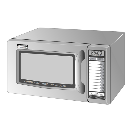
1000W / R-21H V
R-21HV
BEFORE SERVICING ......................................................................................................INSIDE FRONT COVER
WARNING TO SERVICE PERSONNEL ................................................................................................................ 1
MICROWAVE MEASUREMENT PROCEDURE ................................................................................................... 2
FOREWORD AND WARNING ............................................................................................................................... 3
PRODUCT SPECIFICATIONS .............................................................................................................................. 4
GENERAL INFORMATION ................................................................................................................................... 4
OPERATION .......................................................................................................................................................... 6
TROUBLESHOOTING GUIDE .............................................................................................................................. 9
TEST PROCEDURE ............................................................................................................................................ 10
TOUCH CONTROL PANEL ................................................................................................................................. 18
COMPONENT REPLACEMENT AND ADJUSTMENT PROCEDURE ................................................................ 25
PICTORIAL DIAGRAM ........................................................................................................................................ 32
CONTROL PANEL CIRCUIT .............................................................................................................................. 33
PRINTED WIRING BOARD ................................................................................................................................. 35
PARTS LIST ........................................................................................................................................................ 36
PACKING AND ACCESSORIES ......................................................................................................................... 41
SHARP CORPORATION
SERVICE MANUAL
MODEL
ON
DEF
NO. X2 CHECK
In the interest of user-safety the oven should be restored to its original
condition and only parts identical to those specified should be used.
WARNING TO SERVICE PERSONNEL: Microwave ovens con-
tain circuitry capable of producing very high voltage and
current, contact with following parts may result in a severe,
possibly fatal, electrical shock. (High Voltage Capacitor, High
Voltage Power Transformer, Magnetron, High Voltage Recti-
fier Assembly, High Voltage Harness etc..)
TABLE OF CONTENTS
LIGHT DUTY
COMMERCIAL
MICROWAVE OVENS
R-21HT
R-21HV
This document has been published to be used for after
sales service only.
The contents are subject to change without notice.
R-21HT
R-21HV
S7814R21HTP//
Page
Advertisement
Table of Contents

Related Manuals for Sharp R-21HT


Summary of Contents for Sharp R-21HT
-
Page 1: Table Of Contents
R-21HT R-21HV SERVICE MANUAL S7814R21HTP// LIGHT DUTY COMMERCIAL MICROWAVE OVENS 1000W / R-21H V R-21HT MODEL NO. X2 CHECK R-21HV In the interest of user-safety the oven should be restored to its original condition and only parts identical to those specified should be used. -
Page 2: Precautions To Be Observed Before And During Servicing To Avoid Possible Exposure To Excessive Microwave Energy
Before servicing an operative unit, perform a microwave emission check as per the Microwave Measurement Procedure outlined in this service manual. If microwave emissions level is in excess of the specified limit, contact SHARP ELECTRONICS CORPORATION immediately @1-800-237-4277. If the unit operates with the door open, service person should 1) tell the user not to operate the oven and 2) contact SHARP ELECTRONICS CORPORATION and the Food and Drug Administration's Center for Devices and Radiological Health immediately. -
Page 3: Warning To Service Personnel
R-21HT R-21HV WARNING TO SERVICE PERSONNEL Microwave ovens contain circuitry capable of pro- ducing very high voltage and current, contact with following parts may result in a severe, possibly fatal, electrical shock. (Example) High Voltage Capacitor, High Voltage Power Trans- former, Magnetron, High Voltage Rectifier Assem- bly, High Voltage Harness etc.. -
Page 4: Microwave Measurement Procedure
R-21HT R-21HV MICROWAVE MEASUREMENT PROCEDURE A. Requirements: 1) Microwave leakage limit (Power density limit): The power density of microwave radiation emitted by a microwave oven should not exceed 1mW/cm at any point 5cm or more from the external surface of the oven, measured prior to acquisition... -
Page 5: Foreword And Warning
MICROWAVE OVEN GENERAL INFORMATION R-21HT/ R-21HV FOREWORD This Manual has been prepared to provide Sharp Electronics Corp. OPERATION Service Personnel with Operation and Service Information for the SHARP MICROWAVE OVENS, R-21HT, R-21HV. It is recommended that service personnel carefully study the entire... -
Page 6: Product Specifications
P-0 ............ No power throughout the cooking time DOUBLE QUANTITY pad EXPRESS DEFROST pad Ten number pads SELECTATIME pad STOP/CLEAR pad SELECATAPOWER pad [R-21HT only] START pad, SET pad CHECK pad, SIGNAL pad Oven Cavity Light Safety Standard UL Listed... - Page 7 7. SELECATAPOWER pad for setting variable power level (R-21HT only) 8. START pad; touch to operate oven after door is closed and time is set 9. SET pad for setting memory 10.CHECK pad for checking...
-
Page 8: Operation
1. The display will show monitor fuse to blow. COOKING CONDITION POWER LEVEL P-0 TO P-90 COOKING (R-21HT only) Program desired cooking time by touching SELECTATIME When Variable Cooking Power is programmed, the 120 pad and the NUMBER pads. When the START pad is volts A.C. - Page 9 R-21HT R-21HV NOTE: Indicates components with potential above 250 V. SCHEMATIC NOTE: CONDITION OF OVEN 1. DOOR CLOSED. APPEARED. THERMAL THERMAL CUT-OUT CUT-OUT MONITOR 125˚C (OVEN) 145˚C (MAG.) FUSE 20A POWER TRANSFORMER AC120V 60 Hz CAPACITOR 0.94 µF CONTROL UNIT...
- Page 10 R-21HT R-21HV DESCRIPTION AND FUNCTION OF COMPONENTS DOOR OPEN MECHANISM 3. If the door is opened, and the primary interlock relay The door is opened by grasping the door handle, refer to (RY2) and secondary interlock switch contacts fail to Figure D-1.
-
Page 11: Troubleshooting Guide
R-21HT R-21HV TROUBLESHOOTING GUIDE Never touch any part in the circuit with your hand or an uninsulated tool while the power supply is connected. When troubleshooting the microwave oven, it is helpful to follow the Sequence of Operation in performing the checks. Many of the possible causes of trouble will require that a specific test be performed. -
Page 12: Test Procedure
R-21HT R-21HV CK = Check / RE = Replace TEST PROCEDURE A B C D E F F G H I J K L CK RE RE RERE RE CK CK CK POSSIBLE CASE DEFECTIVE PARTS PROBLEM CONDITION Home fuse or circuit breaker blows when power cord is plugged into wall outlet. - Page 13 R-21HT R-21HV TEST PROCEDURES PROCEDURE COMPONENT TEST LETTER 8. Reconnect the power supply cord after the outer case is installed. 9. Run the oven and check all functions. MICROWAVE OUTPUT POWER The following test procedure should be carried out with the microwave oven in a fully assembled condition (outer case fitted).
- Page 14 R-21HT R-21HV TEST PROCEDURES PROCEDURE COMPONENT TEST LETTER the rectifier is probably defective and should be replaced. 5. Reconnect all leads removed from components during testing. 6. Reinstall the outer case (cabinet). 7. Reconnect the power supply cord after the outer case is installed.
- Page 15 R-21HT R-21HV TEST PROCEDURES PROCEDURE COMPONENT TEST LETTER 3. Discharge high voltage capacitor. 4. Isolate the switch and connect the ohmmeter to the common (COM.) and normally open (NO) terminal of the switch. The meter should indicate an open circuit with the door open and a closed circuit with the door closed.
- Page 16 R-21HT R-21HV TEST PROCEDURES PROCEDURE COMPONENT TEST LETTER BLOWN MONITOR FUSE TEST 1. Disconnect the power supply cord, and then remove outer case. 2. Open the door and block it open. 3. Discharge high voltage capacitor. 4. If the monitor fuse is blown when the door is opened, check the primary interlock relay, secondary interlock switch and monitor switch according to the "TEST PROCEDURE"...
- Page 17 R-21HT R-21HV TEST PROCEDURES PROCEDURE COMPONENT TEST LETTER 7) Reconnect the power supply cord after the outer case is installed. 8) Run the oven and check all functions. 2. Control Unit. The following symptoms indicate a defective control unit. Before replacing the control unit, perform the Key unit test (Procedure J) to determine if control unit is faulty.
- Page 18 R-21HT R-21HV TEST PROCEDURES PROCEDURE COMPONENT TEST LETTER RELAY TEST 1. Disconnect the power supply cord, and then remove outer case. 2. Open the door and block it open. 3. Discharge high voltage capacitor. 4. Disconnect the leads to the primary of the power transformer.
- Page 19 R-21HT R-21HV TEST PROCEDURES PROCEDURE COMPONENT TEST LETTER 6) Reconnect all leads removed from components during testing. 7) Re-install the outer case (cabinet). 8) Reconnect the power supply cord after the outer case is installed. 9) Run the oven and check all functions.
-
Page 20: Touch Control Panel
R-21HT R-21HV TOUCH CONTROL PANEL ASSEMBLY OUTLINE OF TOUCH CONTROL PANEL The touch control section consists of the following units This model has 20 Memory pads. as shown in the touch control panel circuit. When the oven is shipped, Memory pad 1 to 10 are set as follows: fig.1. - Page 21 R-21HT R-21HV DESCRIPTION OF LSI LSI(IZA897DR) The I/O signal of the LSI(IZA897DR) is detailed in the following table. Pin No. Signal Description Power source voltage: +5V. VC voltage of power source circuit input. VEE/AVSS Connected to GND VREF Connected to VC. (+5V) AN7-AN6 Terminal not used.
- Page 22 R-21HT R-21HV Pin No. Signal Description 22-24 P44-P42 Digit selection signal. Signal similar to P45. INT1 Signal synchronized with commercial power source frequency. H : +5V This is basic timing for all time processing of LSI. L : GND 16.7 msec Connected to GND through resistor.
- Page 23 R-21HT R-21HV Pin No. Signal Description Key strobe signal. Signal applied to touch-key section. A pulse signal is input to P27, P26, P25 and P24 terminals while one of G5 line keys on key matrix is touched. Key strobe signal.
- Page 24 R-21HT R-21HV TOUCH CONTROL PANEL SERVICING 1. Precautions for Handling Electronic Components 4) Re-install the outer case (cabinet). This unit uses CMOS LSI in the integral part of the 5) Re-connect the power supply cord after the outer circuits. When handling these parts, the following case is installed.
- Page 25 R-21HT R-21HV PROCEDURE FOR CHECKING/CLEARING 3) Practice for inputting total using times (Ex. 310000 times)..Flashing / ... 0.1sec BUZZER SERVICE COUNTS OF MICROWAVE OVEN DISPLAY INDICATOR PHONE The following procedure enables the servicer to obtain the (Door close)
- Page 26 3 : To input using times of Express Defrost, touch EXPRESS key is entered, otherwise it is paused at the end of each stage. DEFROST key at above step #A. #4 : For R-21HT, change selectapower key to signal key.
-
Page 27: Component Replacement And Adjustment Procedure
3. The door gasket or seal is damaged. 4. If the outer case (cabinet) is not fitted. WARNING FOR WIRING To prevent an electric shock, take the following pre- 3) Sharp edge: cautions. Bottom plate, Oven cavity, Waveguide flange, 1. Before wiring, Chassis support and other metallic plate. - Page 28 R-21HT R-21HV POWER TRANSFORMER REMOVAL 1. Disconnect the power supply cord and then remove 6. Disconnect the main wire harness from the power outer case. transformer. 2. Open the oven door and block it open. 7. Remove the two (2) screws holding the transformer to 3.
- Page 29 R-21HT R-21HV OVEN LAMP AND LAMP SOCKET REMOVAL Oven lamp 1. Disconnect the power supply cord and then remove socket outer case. 2. Open the door and block it open. Terminal 3. Discharge high voltage capacitor. Wire lead 4. Lift up the oven lamp socket from air intake duct.
- Page 30 R-21HT R-21HV 4. Install the fan blade to the shaft of fan motor by pushing * Make sure that the axis of the shaft is not slanted. the fan blade with a small, light weight, ball peen hammer 5. Install the fan duct to the oven cavity rear plate with the or rubber mallet.
-
Page 31: Pictorial Diagram
R-21HT R-21HV oven cavity. Latch Hook 7. Remove the latch hook. 8. Push the retaining tab outward slightly and remove the switch. Tabs Re-install Secondary 1. Re-install each switch in its place. The door sensing Interlock Switch switch and monitor switch are in the lower position and the secondary interlock switch is in the upper position. - Page 32 R-21HT R-21HV RE-INSTALL OF THE DOOR Choke Cover 1. Re-install all door parts except the choke cover. 2. Catch two (2) pins of door panel on two (2) holes of upper and lower oven hinges. 3. Re-install choke cover to door panel by pushing.
- Page 33 R-21HT R-21HV INSTALLATION OF CERAMIC SHELF 1. Disconnect the power supply cord. WARNING 2. Open the door and block it open. 3. Make sure that the smooth surface of the ceramic shelf Make sure that the rubber packing is not caught between the oven door and the oven cavity front plate, to avoid face up.
- Page 34 R-21HT R-21HV...
-
Page 35: Control Panel Circuit
R-21HT R-21HV... - Page 36 R-21HT R-21HV...
-
Page 37: Printed Wiring Board
R-21HT R-21HV (C83) (C82) (C81) (C80) (R91) (R90) (JJ) (R89) (R66) (C64) (R69) (JH) (R65) (R68) (C60) (R60) (R62) (C101) (C60) (J5) (JG) (JD) (R61) (J6) (JE) (R64) (R63) (C63) (CN - H) (JA) (R1) (ZD1) (R2) (R101) (14) (15) -
Page 38: Parts List
Thermal cut-out 125 deg. (OVEN) 1-14 RTRN-A570WRE0 Power transformer ∆ 1-15 RV-MZA197WRE0 Magnetron CABINET PARTS 2- 1 GCABUA672WRP0 Outer case cabinet [R-21HT] 2- 1 GCABUA674WRP0 Outer case cabinet [R-21HV] 2- 2 GDAI-A311WRW0 Base plate 2- 3 GCOVHA393WRW0 Base plate cover 2- 4 GLEGPA074WRE0... - Page 39 Touch control transformer VRS1 RH-VZA032DRE0 Varistor (10G471K) VHEHZ4A2///-1 Zener diode (HZ4A2) 3- 2 FPNLCB388WRK0 Control panel frame with key unit [R-21HT] 3- 2 FPNLCB389WRK0 Control panel frame with key unit [R-21HV] 3- 2-1 FUNTKA880WRE0 Key unit [R-21HT] 3- 2-1 FUNTKA881WRE0...
- Page 40 To have your order filled promptly and correctly, please furnish the following information. 1. MODEL NUMBER 2. REF. NO. 3. PART NO. 4. DESCRIPTION Order Parts from the authorized SHARP parts Distributor for your area. Defective parts requiring return should be returned as indicated in the Service Policy.
- Page 41 R-21HT R-21HV OVEN AND CABINET PARTS 1-10 4-28 7-13 4-10 7-13 7-13 4-25 7-12 4-32 4-26 1-13 4-34 4-26 4-24 4-15 4-27 4-14 4-15 4-36 4-16 7-10 7-11 1-12 4-23 4-18 4-20 4-24 4-21 4-20 4-21 4-21 4-22 4-20 4-13...
- Page 42 R-21HT R-21HV CONTROL PANEL PARTS 3-2-3 3-2-2 DOOR PARTS 3-2-1 5-15 5-17 5-16 5-13 5-16 5-20 5-16 5-13 5-4-2 5-16 5-4-1 5-4-3 5-16 5-16 5-12 5-14 5-19 5-12 5-18 5-11 5-19 MISCELLANEOUS 5-10 Actual wire harness may be different from illustration.
-
Page 43: Packing And Accessories
R-21HT R-21HV PACKING AND ACCESSORIES TOP PAD ASSEMBLY (FPADBA385WRK0) WRAP COVER (SSAKHA034WRE0) TRAY HOLDER DOOR PROTECTION SHEET (SPADFA435WRE0) (SPADPA204WRE0) MENU STICKER BOTTOM PAD ASSEMBLY (FPADBA386WRK0) INSTRUCTION BOOK PACKING CASE Not Replaceable Items. SPAKCD113WRE0 [R-21HT] SPAKCD115WRE0 [R-21HV]... - Page 44 No part of this publication may be repro- duced, stored in retrieval systems, or trans- mitted in any form or by any means, elec- tronic, mechanical, photocopying, record- ing, or otherwise, without prior written per- mission of the publisher. '98 SHARP CORP. (7S2.530E) Printed in U.S.A...