Table of Contents
Advertisement
Quick Links
Advertisement
Table of Contents

Related Manuals for Dell S5448F-ON


Summary of Contents for Dell S5448F-ON
- Page 1 Dell EMC PowerSwitch S5448F-ON Installation Guide March 2022 March 2022 Rev. A01...
- Page 2 A WARNING indicates a potential for property damage, personal injury, or death. © 2021 - 2022 Dell Inc. or its subsidiaries. All rights reserved. Dell, EMC, and other trademarks are trademarks of Dell Inc. or its subsidiaries. Other trademarks may be trademarks of their respective owners.
-
Page 3: Table Of Contents
Contents Chapter 1: About this guide......................5 Related documents................................5 Information symbols................................6 Documentation Feedback..............................6 Chapter 2: The S5448F-ON switch....................7 Introduction................................... 7 20W optic port locations..............................8 Features....................................8 Physical dimensions................................9 LED display.................................... 9 LED behavior...................................9 Prerequisites..................................11 S5448F-ON switch configurations..........................11 Luggage tag..................................12... - Page 4 USA Federal Communications Commission statement.................... 52 European Union EMC directive conformance statement..................52 India...................................... 53 Japan VCCI compliance for class A equipment......................53 Safety standards and compliance agency certifications..................53 Electromagnetic compatibility ............................54 Product recycling and disposal............................54 Chapter 11: Dell EMC support...................... 56 Contents...
-
Page 5: Chapter 1: About This Guide
Avoid exposure to laser radiation. Do not stare into open apertures. Regulatory Marketing model S5448F-ON is represented by the regulatory model E50W and the regulatory type E50W001. BMC, ONIE, and DIAG OS default login After you have installed and powered up your switch, you must enter the default username and password. -
Page 6: Information Symbols
● Email—Send your feedback to networkingpub.feedback@dell.com. Include the document title, release number, chapter title, and section title of the text corresponding to the feedback. To get answers to your questions related to Dell EMC products through email, chat, or call, go to the Technical Support page. -
Page 7: Chapter 2: The S5448F-On Switch
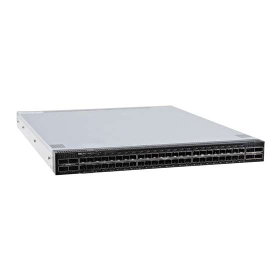
Luggage tag Introduction The S5448F-ON top-of-rack (TOR) switch is a one rack-unit access and aggregation switch/router product for 10/25/50/100/200/400GbE Data Center networks. The S5448F-ON supports 48 SFP56-DD 100 GbE ports, eight QSFP56-DD 400 GbE ports, and two 10 GbE SFP+ ports. You can also use this switch as a 25/50/100GbE switch using 25/50/100 GbE breakout for connections to switches, servers, and storage. -
Page 8: 20W Optic Port Locations
6. Luggage tag The S5448F-ON switch has one RJ45 serial console port, one 10/100/1000 Base-T Ethernet management port, and one USB type-A port for the external storage. The BMC manages system thermal monitoring and fan control. Management ports are on the PSU-side of the switch. -
Page 9: Physical Dimensions
● Fan tray handle 25.0 mm (0.99 in) LED display The S5448F-ON switch includes LED displays on the I/O side of the switch. This section describes open networking installation environment (ONIE) LED behaviors. Some LED behaviors may change after you install your software. - Page 10 Table 1. S5448F-ON switch LED behavior (continued) Description ● Flashing green—Booting ● Solid yellow—Critical system error ● Flashing yellow—Noncritical system error, fan failure, or power supply failure Power LED ● Off—No power ● Solid Green—Normal operation ● Solid yellow—POST is in process ●...
-
Page 11: Prerequisites
You can order the S5448F-ON switch in several different configurations. ● S5448F-ON AC or DC Normal Airflow switch—one U, 48 x 100 GbE SFP56-DD ports, eight x 400 GbE QSFP56-DD ports, two 10 GbE SFP+ ports, two power supplies, and six fan subsystems ●... -
Page 12: Luggage Tag
400 GbE ports. Reverse airflow switches do not support high-power cables or optics. 400 GbE transceivers and active cables may exceed High-Power Optics for SmartFabric OS10 Dell EMC the supported threshold. For more information, see the PowerSwitch S5448F-ON. -
Page 13: Chapter 3: Site Preparations
For more information about switch storage and environmental temperatures, see Specifications. Cabinet placement Install the S5448F-ON switch only in indoor cabinets that are designed for use in a controlled environment. Do not install the switch in outside cabinets. For cabinet placement requirements, see Site selection. -
Page 14: Rack Mounting
The S5448F-ON switch fans support two airflow options: normal and reverse. Fan combinations Fan installation is done as part of the factory install based on stock keeping unit (SKU) type. The S5448F-ON switch has SKUs that support the following configurations: ●... -
Page 15: Power
You do not see module LEDs when the switch power up in ONIE as the software controls the modules. Storing components If you do not install your S5448F-ON switch and components immediately, properly store the switch and all components using these guidelines: ●... -
Page 16: Chapter 4: S5448F-On Switch Installation
ESD damage can occur if components are mishandled. Always wear an ESD-preventive wrist or heel ground strap when handling the S5448F-ON switch and components. As with all electrical devices of this type, take all the necessary safety precautions to prevent injury when installing this switch. -
Page 17: Rack Or Cabinet Hardware Installation Procedure
Rack or cabinet hardware installation procedure You may either place the S5448F-ON on a rack shelf or mount the switch directly into a 19" wide, EIA-310- E-compliant rack. These installation procedures are for four-post rack installation only. The rails system includes separately packaged rail assemblies. - Page 18 4. Attach the inner rail to the switch. Line up the slot on the inner rail with the T-stud on the switch. Push back to lock the rail into place. Secure the inner rail to the switch using two M4 screws. S5448F-ON switch installation...
- Page 19 Secure the outer rail to the back of the rack using two M4 screws for each rail. Repeat this step to attach the second outer rail to the other side of the rack. 6. Slide the inner rails into the outer rails. S5448F-ON switch installation...
- Page 20 7. Attach the L-brackets to the front of the four-post rack. Align the L-bracket holes to the holes at the front of the four-post rack. Secure the L-brackets to the front of the rack using two M4 screws for each side. S5448F-ON switch installation...
-
Page 21: Four-Post Readyrail Installation
You need a user-supplied Phillips screwdriver to complete this installation. To install the switch: 1. Remove the rails, rail plates, and screws from the shipping container. 2. Separate the inner rail and the outer rail. Press the rail clip and pull the inner rail out. S5448F-ON switch installation... - Page 22 4. Confirm the rack mounting hole type and choose the correct components--EIA 9.5 mm (.354 in) square hole, EIA 7.1 mm (.279 in) round hole, or threaded hole. For EIA 9.5 mm (.354 in) square hole racks (default setting for the outer rail): S5448F-ON switch installation...
- Page 23 5. Attach the outer rail to the back of the four-post rack. Align the outer rail pegs to the back of the four-post rack and push towards the back to lock the outer rail to the rear post. The rail clicks into place. Threaded mounting rack S5448F-ON switch installation...
- Page 24 9.5 mm square hole rack EIA 7.1 mm (.279 in) round hole rack S5448F-ON switch installation...
- Page 25 8. Slide the inner rails attached to the switch into the outer rails that are attached to the rails. NOTE: Press the spring clip on each outer rail to allow the switch to slide into the outer rail. S5448F-ON switch installation...
- Page 26 9. Tighten the thumbscrews to secure the switch to the rack. To remove the switch, press the rail spring clip and pull the inner rail and switch out of the outer rail and rack. S5448F-ON switch installation...
-
Page 27: Optics Installation
400 GbE ports. Reverse airflow switches do not support high-power cables or optics. 400 GbE transceivers and active cables may exceed High-Power Optics for SmartFabric OS10 Dell EMC the supported threshold. For more information, see the PowerSwitch S5448F-ON. -
Page 28: Optics Removal
Switch startup Supply power to the S5448F-ON switch after it is mounted in a rack or cabinet. Dell Technologies recommends reinspecting your switch before powering it up. Verify the following: ● Optional: The equipment is properly secured to the rack and properly grounded. - Page 29 NOTE: Some steps do not apply if you are replacing a different switch or non-Dell EMC switch. NOTE: ESD damage can occur when components are mishandled. Always wear an ESD-preventive wrist or heel ground strap when handling the switch and accessories. After you remove the original packaging, place the switch and components on an anti-static surface.
-
Page 30: Chapter 5: Power Supplies
Power supplies The S5448F-ON switch ships with two AC or DC power supplies. The two power supplies have two air-flow directions—from the I/O to the PSU and from the PSU to the I/O. CAUTION: PSU and fan airflow directions must match. To avoid damage to the switch, do not mix normal and reverse airflows in a single switch. -
Page 31: Ac Or Dc Power Supply Installation
4. Plug in the appropriate AC three-prong cable from the switch PSU to the external power source. 5. Repeat steps 1 through 4 if you have a redundant PSU using the second PSU slot on the S5448F-ON switch. 1. When facing the PSU-side of the switch, PSU1 is on the left side of the switch. PSU2 is on the right side of the switch. -
Page 32: Ac Or Dc Power Supply Replacement
= 45-degree C minimum. The altitude of operation is 5000 m. The product must be supplied by a UL-Listed DC power source that is separated from AC mains by double or reinforced insulation when the switch is connected to DC power. For more information, contact your Dell sales representative. NOTE: You need a user-supplied Philips screwdriver to complete this installation. - Page 33 3. Use a user-supplied flat-head screwdriver to tighten the screws that secures the bare wires into the wiring block. 4. Remove the tape and plastic cover, the two M4 screws and one M5 screw from the PSU socket. Keep all the removed parts. 5.
- Page 34 NOTE: To uninstall the cable from the DC PSU, remove the plastic cover and unscrew the M4 and M5 screws. Pull the DC cable out from the DC PSU socket. Power supplies...
-
Page 35: Chapter 6: Fans
Fans The S5448F-ON switch comes from the factory with two PSUs and six fan modules that are installed in the switch. The fan modules and power supplies, which have integrated fans, are hot-swappable. Besides the power supply modules, you can order and install fan modules separately. -
Page 36: Components
● Flashing yellow—There is a fan fault. ● Off—Fan is off. Fan module installation The fan modules in the S5448F-ON switch are field replaceable. CAUTION: DO NOT mix airflow directions. All fans must use the same airflow direction—reverse or normal. If you must correct the mixed airflow . -
Page 37: Fan Module Replacement
Fan module replacement To request a hardware replacement, see https://www.dell.com/support/. CAUTION: Complete the following steps within one minute or the switch temperature could rise above safe thresholds and the switch could shut down: 1. Take the replacement fan module out of the shipping box. -
Page 38: Chapter 7: Management Ports
Management ports The S5448F-ON switch provides three ports for management and one USB flash drive mount for file transfers. NOTE: The output examples in this section are for reference only. Your output may vary. Topics: • RJ45 console port access •... -
Page 39: Micro-Usb-B Console Port Access
The MicroUSB-B console port is on the I/O side of the switch. NOTE: The S5448F-ON switches use the Silicon Labs CP2102 USB-B chip. To find the correct USB-B universal asynchronous receiver-transmitter (UART) driver, see the Downloads section of the https://www.silabs.com/products/ development-tools/software/usb-to-uart-bridge-vcp-drivers site. -
Page 40: Chapter 8: Secure Boot
GRUB locates the SHIM LOCK protocol and registers the SHIM verify function to be used after any load image it performs. Thereafter, the image that is loaded by GRUB is verified before it is run. Secure boot keys Secure boot supports the following keys: ● Dell Networking ● Microsoft ● Cumulus ● Big Switch Networks Secure boot files For secure boot, the .bin file is replaced with the .tar file. -
Page 41: Enable Bios Secure Boot
Installing ONIE on: /dev/sda ONIE: Success: Firmware update URL: file:///lib/onie/onie-updater.tar ONIE: Success: Firmware update version: x.xx.x.x-x ONIE: Rebooting... discover: ONIE embed mode detected. Stopping: discover...start-stop-daemon: warning: killing process 897: No such process done. Topics: • Enable BIOS secure boot • Disable BIOS secure boot Enable BIOS secure boot The Secure Boot configuration page in the BIOS Setup menu is password protected. - Page 42 3. Select the Secure Boot option at the bottom of the Security tab using the down arrow key. 4. Select Enable Secure Boot using the down arrow key. Secure boot...
- Page 43 5. Enable Secure Boot. Use the down arrow key to select Enabled. 6. Go to the Save & Exit tab. 7. Select Save Changes and Reset to reset the switch using the down arrow key. 8. Select Yes at the Save Configuration and Reset? option. After the switch reloads, Secure Boot mode is enabled.
-
Page 44: Disable Bios Secure Boot
Disable BIOS secure boot The Secure Boot configuration page in the BIOS Setup menu is password protected. On some switches, Secure Boot mode is enabled by default in the BIOS but you can disable it from the BIOS menu. 1. Enter the BIOS password. The default password is the switch service tag plus an exclamation mark; for example, xxxxxx!. After you enter the BIOS password, you enter the Main tab of the BIOS user interface. - Page 45 4. Select Enable Secure Boot using the down arrow key. 5. Select Disable. 6. Go to the Save & Exit tab. 7. Select Save Changes and Reset to reset the switch using the down arrow key. Secure boot...
- Page 46 8. Select Yes at the Save Configuration and Reset? option. After the switch reloads, Secure Boot mode is disabled. Secure boot...
-
Page 47: Chapter 9: Before You Install An Operating System
Drivers and Downloads page for your switch as www.dell.com/support. After powering on the S5448F-ON switch, it goes through a power-on self-test (POST). POST runs every time that the switch is initialized and checks the hardware components to determine if the switch is fully operational before booting. After POST, the switch uses the Grub bootloader. -
Page 48: Check Your Switch
NOTE: After you have securely installed and powered on the S5448F-ON switch, to configure your switch, see your third-party ONIE-compatible operating system or the Dell EMC operating system documentation. Topics: • Check your switch • ONIE service discovery Check your switch To confirm that ONIE is working properly, use the onie-sysinfo command. - Page 49 64 bytes from xx.xx.x.xx: seq=1 ttl=62 time=0.577 ms Before you install an operating system...
-
Page 50: Chapter 10: Specifications
Specifications This section lists the S5448F-ON switch specifications. CAUTION: Operate the product at an ambient temperature not higher than 45°C (113°F). NOTE: For RoHS information, see Restricted Material Compliance. Topics: • Chassis physical design • IEEE standards • Agency compliance •... -
Page 51: Ieee Standards
● 133 A /1600 W at 230 VAC ● 91 A/1100 W at 100 VAC IEEE standards The S5448F-ON switch complies with the following Dell EMC SmartFabric OS10 IEEE standards: ● 802.1ab (LLDP) ● TIA-1057 (LLDP-MED) ● 802.3ad (Link Aggregation) ●... -
Page 52: Agency Compliance
Properly shielded and grounded cables and connectors must be used in order to meet FCC emission limits. Dell EMC is not responsible for any radio or television interference caused by using other than recommended cables and connectors or by unauthorized changes or modifications in the equipment. -
Page 53: India
Equipment (VCCI). If this equipment is used in a domestic environment, radio disturbance may arise. When such trouble occurs, the user may be required to take corrective actions. NOTE: Use the AC power cords with Dell EMC equipment only. Do not use Dell EMC AC power cords with any unauthorized hardware. Figure 4. Japan: warning label... -
Page 54: Electromagnetic Compatibility
Product recycling and disposal You must recycle or discard this switch according to applicable local and national regulations. Dell EMC encourages owners of information technology (IT) equipment to responsibly recycle their equipment when it is no longer needed. Dell EMC offers a variety of product return programs and services in several countries to assist equipment owners in recycling their IT products. - Page 55 EEE on the environment and human health due to the potential presence of hazardous substances in EEE. Dell EMC products, which fall within the scope of the WEEE, are labeled with the crossed-out wheelie-bin symbol, as shown above, as required by WEEE.
-
Page 56: Chapter 11: Dell Emc Support
Dell EMC support The Dell EMC support site provides documents and tools to help you use Dell EMC equipment and mitigate network outages. Through the support site you can obtain technical information, access software upgrades and patches, download available management software, and manage your open cases. The Dell EMC support site provides integrated, secure access to these services.