
Related Manuals for National Instruments ISC-1772


Summary of Contents for National Instruments ISC-1772
- Page 1 National Instruments ISC-1772 Manual Get Pricing & Availability at ApexWaves.com Call Today: 1-800-915-6216 Email: sales@apexwaves.com https://www.apexwaves.com/modular-systems/national-instruments/smart-cameras/ISC-1772...
- Page 2 NI Vision NI 177x Smart Camera User Manual NI 177x Smart Camera User Manual September 2011 373491A-01...
- Page 3 For further support information, refer to the Technical Support and Professional Services appendix. To comment on National Instruments documentation, refer to the National Instruments Web site at ni.com/info and enter the Info Code feedback. © 2011 National Instruments Corporation. All rights reserved.
- Page 4 Instruments Corporation. National Instruments respects the intellectual property of others, and we ask our users to do the same. NI software is protected by copyright and other intellectual property laws. Where NI software may be used to reproduce software or other materials belonging to others, you may use NI software only to reproduce materials that you may reproduce in accordance with the terms of any applicable license or other legal restriction.
- Page 5 Furthermore, any changes or modifications to the product not expressly approved by National Instruments could void your authority to operate it under your local regulatory rules.
-
Page 6: Table Of Contents
Acquire an Image with Vision Builder AI ............2-3 Configuring the NI Smart Camera with LabVIEW ............2-4 Configure the IP Address ................2-5 Install Software on the NI Smart Camera............2-6 Acquire an Image ....................2-6 © National Instruments Corporation NI 177x Smart Camera User Manual... - Page 7 Contents NI 177x Smart Camera Technical Reference Chapter 3 Connectors I/O Connector ........................ 3-2 NI Smart Camera Power Requirements ................ 3-4 100/1G Connector ......................3-4 VGA/USB Connector....................3-5 Chapter 4 Connecting Lighting and External Devices Connecting Lighting Devices ..................4-1 Connecting a Light Controller ................
- Page 8 Status Indicator....................7-2 User Indicator ....................7-3 100/1G Indicator....................7-4 Chapter 8 Mounting Information Appendix A Specifications Appendix B Camera Attributes Appendix C Accessories Appendix D Technical Support and Professional Services Glossary Index © National Instruments Corporation NI 177x Smart Camera User Manual...
-
Page 9: About This Manual
About This Manual This manual contains detailed installation instructions and electrical and mechanical information for the National Instruments 177x Smart Camera. Conventions The following conventions appear in this manual: » The » symbol leads you through nested menu items and dialog box options to a final action. -
Page 10: Related Documentation
The NI Developer Zone is located on the National Instruments Web site at ni.com/zone NI Vision Builder for Automated Inspection Documents •... -
Page 11: Labview And Ni Vision Development Module Documents
LabVIEW VIs and properties for NI-IMAQdx driver software. • Measurement & Automation Explorer Help for NI-IMAQdx—Describes how to configure NI-IMAQdx driver software, NI image acquisition devices, and NI Smart Cameras using Measurement & Automation Explorer. © National Instruments Corporation NI 177x Smart Camera User Manual... -
Page 12: Parti
Instructions for configuring the NI 177x Smart Camera hardware • Basic information about software options for application development • Instructions for acquiring your first image with the NI 177x Smart Camera using the selected application development software © National Instruments Corporation NI 177x Smart Camera User Manual... -
Page 13: Hardware Overview And Installation
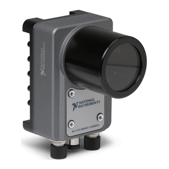
NI 177X SMART CAMERA 1 Image Sensor 5 I/O Connector 2 C-Mount 6 100/1G Connector 3 Lens Cover Mount 7 VGA/USB Connector 4 LED Indicators Figure 1-1. NI 177x Smart Camera © National Instruments Corporation NI 177x Smart Camera User Manual... -
Page 14: Hardware Overview
Chapter 1 Hardware Overview and Installation Hardware Overview ® ™ NI 177x Smart Cameras incorporate an Intel Atom Z530 (1.60 GHz) processor, image sensor, and digital I/O M12 connectors in a compact, rugged, IP67 rated housing. Refer to the I/O Connector section of Chapter 3, Connectors, for more information about the digital I/O capabilities of the device. -
Page 15: Connect The Power Supply And I/O
Chapter 1 Hardware Overview and Installation Connect the Power Supply and I/O National Instruments provides the following two cable options for connecting a power supply (782032-01) and I/O to the NI 177x Smart Camera. • Power and I/O Accessory (781993-01)—A terminal block that simplifies power and I/O signal configuration for the NI 177x Smart Camera. - Page 16 Chapter 1 Hardware Overview and Installation Figure 1-2. Connecting the NI 177x Smart Camera to the Power and I/O Accessory Connect and secure the 17-pin M12 connector on the I/O cable to the I/O connector on the NI 177x Smart Camera. Connect and secure the 25-pin D-SUB connector on the I/O cable to the CAMERA connector on the terminal block.
-
Page 17: Connect To The Development Computer
Caution To prevent data loss and to maintain the integrity of your Ethernet installation, do not use a cable longer than 100 m. National Instruments recommends using a shielded twisted pair cable for maximum signal integrity. Direct Connection To connect the NI 177x Smart Camera directly to the development computer, complete the following steps. -
Page 18: Subnet Considerations
Chapter 1 Hardware Overview and Installation Subnet Considerations To use the NI 177x Smart Camera on a subnet other than the one on which the development computer resides, first connect and configure the NI 177x Smart Camera on the same subnet as the development computer. Next, physically move the NI 177x Smart Camera. -
Page 19: Firewall Configuration
Reserved as nati-vi-server (NATI VI Server). Used by Vision Builder for Automated Inspection to configure a remote NI Smart Camera. If your firewall is controlled remotely or you are unsure about configuring the firewall, contact your network administrator. © National Instruments Corporation NI 177x Smart Camera User Manual... -
Page 20: Software Overview
Caution National Instruments software may require you to update the firmware for this device. Do not remove power from the device until the software indicates that the firmware update is complete. Removing power during a firmware update could cause your device to become unusable. -
Page 21: Configuring The Ni Smart Camera With Vision Builder Ai
Chapter 2 Software Overview Configuring the NI Smart Camera with Vision Builder AI Vision Builder AI is interactive, menu-driven configuration software for developing, benchmarking, and deploying machine vision applications. With Vision Builder AI, you can perform powerful visual inspection tasks and make decisions based on the results of individual tasks. -
Page 22: Install Software On The Ni Smart Camera
Click the Browse button next to the Software Image to Install on the Target control. Navigate to the Vision Builder AI software image you want to use, and click OK. Software images provided by National Instruments are installed to the directory, where <Vision Builder AI>\RT Images... -
Page 23: Configuring The Ni Smart Camera With Labview
• NI Vision Acquisition Software—Includes Measurement & Automation Explorer (MAX), the National Instruments configuration utility, and NI-IMAQdx driver software for acquiring images and controlling I/O using the NI 177x Smart Camera. The latest version of NI Vision Acquisition software is included with the NI 177x Smart Camera. -
Page 24: Configure The Ip Address
Chapter 2 Software Overview Documentation for the NI-IMAQdx driver software is available by selecting Start»All Programs»National Instruments»Vision» Documentation»NI-IMAQdx. NI Vision Development Module—Refer to the NI Vision Development Module Readme on the NI Vision Development Module installation media for system requirements and installation instructions. -
Page 25: Install Software On The Ni Smart Camera
Chapter 2 Software Overview If you want to prevent other users from resetting the NI 177x Smart Camera, click the Lock button on the MAX toolbar to set up password protection. To require users to enter the password before restarting the device, enable the Password-protect Resets checkbox. - Page 26 Information about acquiring an image with the NI 177x Smart Camera • Descriptions and blink code explanations for the LED indicators • Information about mounting the NI 177x Smart Camera © National Instruments Corporation II-1 NI 177x Smart Camera User Manual...
- Page 27 Connector Type Description I/O connector 17-pin male M12 Power and I/O connection 100/1G connector 8-pin female M12 10/100/1000 Mb/s Ethernet connection VGA/USB 12-pin male M12 Analog video and connector USB connection © National Instruments Corporation NI 177x Smart Camera User Manual...
-
Page 28: I/O Connector
Chapter 3 Connectors I/O Connector The I/O connector is a 17-pin male M12 connector that provides power to the camera and transmits digital I/O signals. Figure 3-2. I/O Connector The I/O connector includes 4 open collector output connections, including 2 output connections which can be used as strobe signals. An open collector output is not capable of providing voltage to a connected device. - Page 29 White/Gray connected to a LED lighting device (0 to 500 mA, generated using exposure timer 2). The negative component of this signal is internally connected to the power supply GND. © National Instruments Corporation NI 177x Smart Camera User Manual...
-
Page 30: Ni Smart Camera Power Requirements
Chapter 3 Connectors NI Smart Camera Power Requirements Use the NI 177x Smart Camera only with a 12 W, 24 VDC ±10%, UL listed, Caution limited power source (LPS) supply. The power supply should bear the UL listed mark, LPS. The power supply must meet any safety and compliance requirements for the country of use. -
Page 31: Vga/Usb Connector
Ethernet Connector 100/1G Connector Pin Number Pin Number VGA/USB Connector The VGA/USB connector is a 12-pin male connector that transmits RGB analog video output and USB signals. Figure 3-4. VGA/USB Connector © National Instruments Corporation NI 177x Smart Camera User Manual... - Page 32 Chapter 3 Connectors The following table lists pin numbers, signal names, and signal descriptions for the VGA/USB connector. Table 3-4. VGA/USB Connector Signals and USB Connector Signals 12-Pn M12 USB Connector Connector Pin Number Signal Name Function Pin Number USB_PWR 5 V supplied from camera USB_DATA+ USB data, positive...
-
Page 33: Connecting Lighting And External Devices
Use a power supply with tolerances that meet the requirements of the controller. © National Instruments Corporation NI 177x Smart Camera User Manual... - Page 34 Chapter 4 Connecting Lighting and External Devices To connect a lighting controller, connect the OUT1 signal to the digital input signal of the lighting controller. The OUT1 signal is an unmodulated signal that can turn the lighting controller on or off. Connect the ground of the NI 177x Smart Camera and the lighting controller to a common ground.
-
Page 35: Open Collector Outputs
Each open collector output can sink up to 100 mA. Note +24 V max OUT0 Input NI 177x Smart Camera NPN-compatible I/O connector PLC device Figure 4-2. Connecting to an External NPN Input Device © National Instruments Corporation NI 177x Smart Camera User Manual... -
Page 36: Connecting To A Pnp Device
Chapter 4 Connecting Lighting and External Devices Connecting to a PNP Device Because a PNP input device requires a sourcing input, you must use an external pull-up resistor. Note that the resistor will invert the output signal so that the open collector output disables the PNP input device. Connect the ground of the NI 177x Smart Camera and the PNP input device to a common ground. - Page 37 Each open collector output can sink up to 100 mA. Note +24 V max External diode OUT0 Sinking input NI 177x Smart Camera PNP-compatible I/O connector PLC device Figure 4-4. Connecting to an External Inductive Load Device © National Instruments Corporation NI 177x Smart Camera User Manual...
-
Page 38: Connecting To A Triggering Device
To wire a NI 177x Smart Camera output directly to the TRIG_IN+ input, you must add a pull up resistor to +24 V as illustrated in Figure 4-6. National Instruments recommends a 3 K-ohm, 1/4 W resistor. Wire the TRIG_IN– input to GND. -
Page 39: Connecting To Serial Devices
Refer to the Serial Hardware and Software Help for information about installing the NI-Serial software on LabVIEW Real-Time targets, such as the NI 177x Smart Camera. To open this document, navigate to Start»All Programs»National Instruments» NI-Serial»NI-Serial Help. © National Instruments Corporation... -
Page 40: Image Sensor
The field of view is the area under inspection that will be imaged by the NI 177x Smart Camera. It is critical to ensure that the field of view of your system includes the object you want to inspect. © National Instruments Corporation NI 177x Smart Camera User Manual... - Page 41 Chapter 5 Image Sensor To calculate the horizontal and vertical field of view (FOV) of your imaging system, use Equation 5-1 and the specifications for the image sensor of your device, as listed in Appendix A, Specifications. × × Pixel Pitch Active Pixels Working Distance -----------------------------------------------------------------------------------------------------------------...
-
Page 42: Image Sensor Spectral Response
For most applications, the NI 177x Smart Camera default gain setting optimizes the balance between small signals and large signals. © National Instruments Corporation NI 177x Smart Camera User Manual... -
Page 43: Auto White Level (Ni 177Xc Smart Cameras)
Chapter 5 Image Sensor Figure 5-2 shows what happens when gain is applied to a signal. a Low Gain b Medium Gain High Gain Figure 5-2. Effect of Gain on the Video Signal In Figure 5-2a, low gain has been applied to the signal. The pixel values in the image are grouped close together. -
Page 44: Black Level (Ni 177Xc Smart Cameras)
Attributes tab of the device configuration page. Refer to the NI Vision for LabVIEW Basics Help for information about a using a LUT transformation to improve images in LabVIEW. To open this document, navigate to Start»All Programs»National Instruments» Vision»Documentation»NI Vision. Note Vision Builder AI does not support LUT editing for NI 177x Smart Cameras. -
Page 45: Maintenance
Chapter 5 Image Sensor Maintenance Do not touch the CCD sensor by hand or with other objects. The sensor can be damaged by electrostatic discharge (ESD), body oils, and particulate matter. Use a lens mount cover whenever a lens is not mounted on the camera to protect the sensor from dust and dirt. -
Page 46: Image Acquisition
Chapter 5, Image Sensor, divided by the number of pixels in the sensor. Together, this information can be used to calculate the maximum exposure. Assuming the object is moving © National Instruments Corporation NI 177x Smart Camera User Manual... -
Page 47: Acquiring Images
Chapter 6 Image Acquisition horizontally across the field of view, use Equation 6-1 to calculate the maximum exposure time. × Horizontal ----------------------------------------------------------------------- - (6-1) ⁄ Horizontal Horizontal where is the maximum exposure time without blurring, R is the rate of motion of the object either horizontally or vertically, FOV is the field of view in the direction of motion, and N is the number of sensor pixels in the direction of motion... -
Page 48: External Trigger
Figure 6-1 illustrates the relationship between an external trigger, a lighting strobe, and the exposure time. Trigger Lighting Strobe Exposure Image Readout 1 User-Configurable Trigger Delay 3 Beginning of Image Readout 2 Lighting Turn-On Time Figure 6-1. Externally Triggered Mode © National Instruments Corporation NI 177x Smart Camera User Manual... - Page 49 Chapter 6 Image Acquisition The trigger shown in Figure 6-1 represents an external trigger, configured to use the rising edge as the active edge. The time between the active edge of the trigger and the assertion of the lighting strobe is a user-configurable trigger delay.
-
Page 50: Maximum Frame Rate
If an incoming trigger is received during exposure, the incoming trigger is ignored. If an incoming trigger is received during readout, the trigger is delayed until readout concludes. © National Instruments Corporation NI 177x Smart Camera User Manual... -
Page 51: Determining The Exposure Time
Chapter 6 Image Acquisition Use Equation 6-2 to understand how software determines the maximum frame rate: max frame rate ------------------------------------------ - (6-2) min frame period where min frame period is the minimum amount of time for the strobe and trigger mode, as described in the Calculating the Minimum Frame Period section. -
Page 52: Led Indicators
The NI 177x Smart Camera includes four multicolor indicators. The following figure illustrates the location of the LED indicators: 100/1G VGA/ 1 LED Indicators Figure 7-1. NI 177x Smart Camera LED Indicators © National Instruments Corporation NI 177x Smart Camera User Manual... -
Page 53: Device Initialization
Chapter 7 LED Indicators Device Initialization While the NI 177x Smart Camera initializes, the Power and Status LED indicators exhibit behavior described in the following table: Table 7-1. LED Indicator Behavior during Device Initialization Indicator Name LED Behavior Power Red for 0.5 seconds then solid green Status Red for 0.5 seconds then off If both the Power and Status indicators continuously display solid red, your... -
Page 54: User Indicator
Smart Camera remains in the exception state, alerting you to resolve the problem. Reinstall software on the NI 177x Smart Camera or contact National Instruments for assistance. User Indicator The User indicator is a user-configurable LED. For example, you can use the indicator to indicate the PASS/FAIL status of an inspection. -
Page 55: 100/1G Indicator
Chapter 7 LED Indicators 100/1G Indicator The 100/1G indicator is a multicolor LED that indicates the status of any network connection. The following table describes the behavior of the 100/1G indicator: Table 7-4. 100/1G LED Indicator Behavior LED Color Description No link or a 10 Mbps link is negotiated Yellow A 100 Mbps link is negotiated... -
Page 56: Mounting Information
Refer to Appendix A, Specifications, for temperature specifications. Figures 8-1 through 8-4 provide the dimensional drawings necessary to create a custom mount for the NI 177x Smart Camera. © National Instruments Corporation NI 177x Smart Camera User Manual... - Page 57 Chapter 8 Mounting Information 2.953 in. (75 mm) 1.240 in. (31.5 mm) 1.299 in. (33 mm) 4.331 in. (110 mm) NATIONAL 1.181 in. INSTRUMENTS (30 mm) NI 177X SMART CAMERA 4X M4 × 0.7 0.138 (3.5 mm) 1.417 in. (36 mm) Figure 8-1.
- Page 58 (98.1 mm) 2.856 in. (72.55 mm) 1.969 in. (50 mm) 0.492 in. 0.492 in. (12.5 mm) (12.5 mm) Figure 8-2. Back View of the NI 177x Smart Camera with Dimensions © National Instruments Corporation NI 177x Smart Camera User Manual...
- Page 59 Chapter 8 Mounting Information 2.953 in. (75 mm) 1.179 in. (29.95 mm) 100/1G VGA/ 0.157 in. (4 mm) 0.83 in. 0.83 in. (21 mm) (21 mm) Figure 8-3. Bottom View of the NI 177x Smart Camera with Dimensions NI 177x Smart Camera User Manual ni.com...
- Page 60 Chapter 8 Mounting Information 3.99 in. (101.35 mm) (REF) 4.331 in. (110 mm) 1.96 in. (49.78 mm) Figure 8-4. Side View of the NI 177x Smart Camera with Dimensions © National Instruments Corporation NI 177x Smart Camera User Manual...
-
Page 61: Appendix A Specifications
Storage ........... 2 GB solid state Opto-Coupled Inputs Channels..........4 Input type ..........Opto-coupled Input current........... 1.6 mA On voltage level ........Greater than 15 V Off voltage level........Less than 0.8 V © National Instruments Corporation NI 177x Smart Camera User Manual... - Page 62 Appendix A Specifications On current (minimum)......0.5 mA Off to on responsiveness......5 μs On to off responsiveness......25 μs Open Collector Outputs Channels ..........4 Output type ..........Open collector Operating voltage range......24 V (max) Sinking current range......0 to 100 mA Maximum current leakage ......10 μA On voltage drop ........25 mV Maximum inrush current ......4 A for 300 μs (max) Off to on responsiveness......250 ns...
- Page 63 Sony 1/1.8 1,600 × 1,200 4.4 × 4.4 ICX274AL (UXGA) NI 1776C Sony ICX274AQ NI 1778 Sony 2,448 × 2,050 3.45 × 3.45 ICX625AL (5 MP) Sensor readout........Progressive scan © National Instruments Corporation NI 177x Smart Camera User Manual...
- Page 64 Appendix A Specifications VGA Sensor Spectral Characteristics NI 1772, monochrome ......Refer to Figure A-1 1000 Wavelength (nm) Figure A-1. 1772 VGA Sensor Spectral Response Curves NI 1772C, color ........Refer to Figure A-2 Green Blue Wavelength (nm) Figure A-2. 1772C VGA Sensor Spectral Response Curves NI 177x Smart Camera User Manual ni.com...
- Page 65 1000 Wavelength (nm) Figure A-3. 1774 SXGA Sensor Spectral Response Curves NI 1774C, color........Refer to Figure A-4 Blue Green Wavelength (nm) Figure A-4. 1774C SXGA Sensor Spectral Response Curves © National Instruments Corporation NI 177x Smart Camera User Manual...
- Page 66 Appendix A Specifications UXGA Sensor Spectral Characteristics NI 1776, monochrome ......Refer to Figure A-5 1000 Wavelength (nm) Figure A-5. 1776 UXGA Sensor Spectral Response Curves NI 1776C, color ........Refer to Figure A-6 Green Blue Wavelength (nm) Figure A-6. 1776C UXGA Sensor Spectral Response Curves NI 177x Smart Camera User Manual ni.com...
- Page 67 The NI Smart Camera is intended for indoor use only. Operating ambient temperature....0 to 50 °C Humidity ..........10% to 90% RH, noncondensing IP rating..........67 Pollution degree ........2 © National Instruments Corporation NI 177x Smart Camera User Manual...
- Page 68 Appendix A Specifications Operating shock (IEC 60068-2-27) ..50 g, 3 ms half sine, 18 shocks at 6 orientations; 30 g, 11 ms half sine, 18 shocks at 6 orientations Operating vibration Random (IEC 60068-2-34)....10 Hz to 500 Hz, 5 Grms Swept sine (IEC 60068-2-6)....10 Hz to 500 Hz, 5 g Approved at altitudes up to 2,000 m.
- Page 69 Instruments WEEE initiatives, and compliance with WEEE Directive 2002/96/EC on Waste and Electronic Equipment, visit ni.com/environment/weee National Instruments (RoHS) National Instruments RoHS ni.com/environment/rohs_china (For information about China RoHS compliance, go to ni.com/environment/rohs_china © National Instruments Corporation NI 177x Smart Camera User Manual...
-
Page 70: Appendix B Camera Attributes
CounterEventActivation Enum Rising Edge, — Gets or sets the activation for the Falling Edge selected counter. CounterReset Command — — Resets the selected counter. © National Instruments Corporation NI 177x Smart Camera User Manual... - Page 71 Appendix B Camera Attributes Table B-1. Camera Attributes (Continued) Attribute Name Data Type Range Unit Description CounterSelector Enum Counter 0, — Specifies the counter to configure. Counter 1, Counter 2, Counter 3 CounterValue 0 to 4294967295 Counts Indicates the value of the selected counter.
- Page 72 Gets or sets the vertical offset of the image. Range depends on the specified image width. OffsetY — Pixels Gets or sets the horizontal offset of the image. Range depends on the specified image height. © National Instruments Corporation NI 177x Smart Camera User Manual...
- Page 73 Appendix B Camera Attributes Table B-1. Camera Attributes (Continued) Attribute Name Data Type Range Unit Description PixelFormat Enum Mono8, — Gets or sets the pixel format of the BGRA8Packed source sensor. Color pixel formats are only available for NI 177xC Smart Cameras.
- Page 74 Specifies which bit in the User User Output 1, Output register to set. User Output 2, User Output 3 UserOutputValue Bool — — Gets or sets the status of the selected user output. © National Instruments Corporation NI 177x Smart Camera User Manual...
- Page 75 Appendix B Camera Attributes Table B-1. Camera Attributes (Continued) Attribute Name Data Type Range Unit Description UserOutputValueAll 0 to 4294967295 — Gets or sets the value of all bits in the User Output register. Width — Pixels Gets or sets the width of the image.
-
Page 76: Appendix C Accessories
Accessories The following sections provide a partial list of the NI 177x Smart Camera accessories available from National Instruments. For a list of all available accessories, visit ni.com/smartcamera Power and I/O Cables and Accessories National Instruments offers the following cables and accessories for power or I/O configuration: Table C-1. - Page 77 Appendix C Accessories Lights, Lenses, and Brackets National Instruments offers the following lenses and lighting accessories: Table C-3. Lights, Lenses, and Brackets Part Description Number Notes 8 mm lens (Computar M0814-MP) 780024-01 f/1.4, 1 MP 12 mm lens (Computar M1214-MP) 780025-01 f/1.4, 1 MP...
- Page 78 Technical Support and Professional Services Visit the following sections of the award-winning National Instruments Web site at for technical support and professional services: ni.com • Support—Technical support at includes the ni.com/support following resources: – Self-Help Technical Resources—For answers and solutions,...
- Page 79 Appendix D Technical Support and Professional Services • Declaration of Conformity (DoC)—A DoC is our claim of compliance with the Council of the European Communities using the manufacturer’s declaration of conformity. This system affords the user protection for electromagnetic compatibility (EMC) and product safety.
- Page 80 A specified number of assertions, rising, falling, or both, in a signal. exposure time The amount of time that light is allowed to strike the imaging sensor to produce an image. © National Instruments Corporation NI 177x Smart Camera User Manual...
- Page 81 Glossary falling edge The digital signal transition from the high state to the low state. field of view The area of inspection that the camera can acquire. Frames per second. gain The amount of increase in signal power, voltage, or current expressed as the ratio of output to input.
- Page 82 Glossary NI-IMAQdx Driver software for National Instruments image acquisition devices and NI 177x Smart Cameras. NI-IMAQdx is installed as part of NI Vision Acquisition Software. open collector An output mechanism that grounds or does not ground a connection to a powered device.
- Page 83 Glossary sensor resolution The number of columns and rows of CCD pixels in the camera sensor. sensor size The size of the active area of an image sensor. sinking A device that requires a powered signal as an input. sourcing A device that provides a powered signal.
- Page 84 The point at which values in the red, green, and blue color planes converge to produce white. working distance The distance from the front of the camera lens to the object under inspection. © National Instruments Corporation NI 177x Smart Camera User Manual...
- Page 85 NPN devices, 4-3 maximum, 6-5 outputs, 4-3 free-run mode, 6-2 power, 1-3 sinking devices, 4-4 sourcing devices, 4-3 connectors, 3-1 gain, 5-3 100/1G, 3-4 I/O, 3-2 help, technical support, D-1 © National Instruments Corporation NI 177x Smart Camera User Manual...
- Page 86 Index I/O connector, 3-2 mounting information, 8-1 pin numbers, 3-2 signal descriptions, 3-3 image sensor, 5-1 National Instruments support and field of view, 5-1 services, D-1 gain, 5-3 network connection, 1-5 maintenance, 5-6 NI 177x spectral response, 5-3 acquiring images, 6-2...
- Page 87 LabVIEW, smart camera configuration, 2-4 NI resources, D-1 NI Vision Builder for Automated Inspection smart camera configuration, 2-2 Status indicator, 7-2 blink codes, 7-3 support, technical, D-1 © National Instruments Corporation NI 177x Smart Camera User Manual...
Need help?
Do you have a question about the ISC-1772 and is the answer not in the manual?
Questions and answers