Table of Contents
Advertisement
Quick Links
This .pdf document is bookmarked
Instructions and Parts Manual
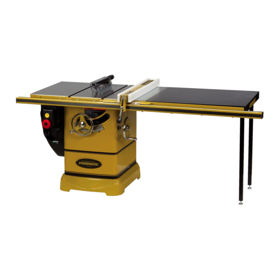
10-inch Cabinet Saw
Model PM2000
Model PM2000 Table Saw shown with optional extension table and legs
WALTER MEIER (Manufacturing) Inc.
427 New Sanford Road
LaVergne, Tennessee 37086
Part No. M-1791997
Ph.: 800-274-6848
Revision D 08/2013
www.powermatic.com
Copyright © 2013 Walter Meier (Manufacturing) Inc.
Advertisement
Table of Contents

Related Manuals for Powermatic 1792017K


Summary of Contents for Powermatic 1792017K
- Page 1 Model PM2000 Model PM2000 Table Saw shown with optional extension table and legs WALTER MEIER (Manufacturing) Inc. 427 New Sanford Road LaVergne, Tennessee 37086 Part No. M-1791997 Ph.: 800-274-6848 Revision D 08/2013 www.powermatic.com Copyright © 2013 Walter Meier (Manufacturing) Inc.
-
Page 2: Warranty And Service
This warranty covers only the initial purchaser of the product. WHAT IS THE PERIOD OF COVERAGE? The general POWERMATIC warranty lasts for the time period specified in the product literature of each product. WHAT IS NOT COVERED? The Five Year Warranty does not cover products used for commercial, industrial or educational purposes. Products with a Five Year Warranty that are used for commercial, industrial or education purposes revert to a One Year Warranty. -
Page 3: Table Of Contents
Table of Contents Warranty and Service ..........................2 Table of Contents ............................ 3 Warnings ..............................4 Introduction ............................. 6 Specifications ............................6 Shipping Contents ........................... 7 Unpacking ............................7 Cleaning .............................. 7 ... -
Page 4: Warnings
Warnings 1. Read and understand the entire owner’s manual before attempting assembly or operation. 2. Read and understand the warnings posted on the machine and in this manual. Failure to comply with all of these warnings may cause serious injury. 3. - Page 5 17. Provide for adequate space surrounding work area and non-glare, overhead lighting. 18. Keep the floor around the machine clean and free of scrap material, oil and grease. 19. Keep visitors a safe distance from the work area. Keep children away. 20.
-
Page 6: Introduction
Introduction This manual is provided by Walter Meier (Manufacturing) Inc., covering the safe operation and maintenance procedures for a Powermatic Model PM2000 Table Saw. This manual contains instructions on installation, safety precautions, general operating procedures, maintenance instructions and parts breakdown. This machine has been designed and constructed to provide years of trouble free operation if used in accordance with instructions set forth in this manual. -
Page 7: Shipping Contents
Shipping Contents Unpacking Remove box and wood crating completely from around saw. Check for shipping damage. Report any damage immediately to your distributor and shipping agent. Do not discard any shipping material until the Table Saw is assembled and running properly. Compare the contents of your container with the parts lists in the next two pages to make sure all parts are intact. -
Page 8: Contents Of The Shipping Container
Contents of the Shipping Container Small Box Main Saw Container The small box consists of the following items: Table Saw (A) Table Insert (B) Push Stick (G) 27mm Arbor Wrench (H) The following items are inside the saw: Lock Knobs (J) Miter Gauge Assembly (C) Swivel Handles (K) Blade Guard Assembly (D) - Page 9 Extension Tables Two extension tables are packaged in individual boxes. Extension Tables Side Cover Box Hinge Pin (N) Side Cover (O) Contents of Side Cover Box Fence and Rail Carton contents and installation instructions for the fence, rail system, and optional wooden extension table are described in the Accu-Fence Owner's Manual (No.
-
Page 10: Assembly
Assembly Mounting Extension Wings Referring to Figure 1: 1. Mount a cast iron extension wing (A) to the right or left side of the table (B) using three each 3/8-16x1 hex head screws (C), 3/8 lock washers (D) and 3/8 flat washers (E). Have an assistant hold the extension wing up to the table while inserting the screws and washers. -
Page 11: Lock Knobs And Swivel Handles
Lock Knobs and Swivel Handles Referring to Figure 4: 1. Thread the swivel handles (A) into the front and side handwheels (C) and tighten with a 14mm wrench. 2. Screw lock knobs (B) into the threaded openings on the end of the shafts located in the middle of the handwheels (C). -
Page 12: Blade Installation/Replacement
Blade Installation/Replacement Use care when working with or around sharp saw blade to prevent injury! To install or replace a blade (refer to Figure 6): 1. Disconnect machine from power source. 2. Raise the blade height all the way up and set the blade tilt to 0º... -
Page 13: Riving Knife And Guard Installation
Riving Knife and Guard Installation Description Referring to Figure 9: The complete riving knife and guard assembly is shown in A. Before installing onto the saw, the anti- kickback pawl (E) must be separated from the riving knife (H) as described below. 1. -
Page 14: Grounding Instructions
Grounding Instructions Adjustments Handwheel Adjustments Electrical connections must be made by a qualified electrician in compliance Referring to Figure 11: with all relevant codes. This machine must be The front handwheel (B) controls the raising and properly grounded to help prevent electrical lowering of the blade (blade height). -
Page 15: Zero-Clearance Insert Setup
Castor system adjustment Retractable castors can be extended permitting the saw to be moved: 1. Loosen the lock knob (A) on the side handwheel (C). 2. Pull the handwheel out (F). 3. Turn the handwheel (C) clockwise to extend the castors, raising the saw. Note: Because of the weight of the machine, both hands will be needed to turn the handwheel. -
Page 16: Miter Slot Alignment
Miter Slot Alignment Disconnect machine from power source before making this adjustment. To check the alignment of the miter slot to the blade: 1. Raise the blade to its maximum height at the 90º vertical position (0º on scale). 2. Mark one tooth with a grease pencil and position the tooth slightly above the top edge of the table at the front. -
Page 17: Precision Miter Gauge
6. Verify that the scale indicator (G) reads 0º. If Precision Miter Gauge further adjustment is necessary: Setting the miter gauge angle 7. Loosen the screw (F) and adjust the indicator (G) until it reads 0º. Referring to Figure 15: 8. -
Page 18: Riving Knife Adjustment
Riving Knife Adjustment Lateral alignment The saw blade and riving knife must be in line as close as possible with each other (lateral alignment) for the prevention of kickback. Upon initial blade guard and riving knife installation no further adjustment should be necessary. Alignment should be checked and adjusted, if required, after each blade change. -
Page 19: Insert Adjustment
Note: These screws are accessible through openings on the floating clamp block (B) located diagonally on either side of the lock handle (A). They secure the fixed clamp block (C) to the riving knife extension plate (F). Loosening these screws (E) will allow the fixed clamp block (C) to slide back and forth on the extension plate (F). -
Page 20: Operating Controls
Operating Controls Start/Stop Power Indicator Light – The start switch has a power indicator lamp which is on whenever there is power connected to the saw, not just when the saw is running. Do not assume that no light means there is no power to the machine. -
Page 21: Operations
Operations Overview Familiarize yourself with the location and operation of all controls and adjustments and the use of accessories such as the miter gauge and rip fence. Kickback Serious injury can result from kickbacks which occur when a work piece binds on the saw blade Figure 23 or binds between the saw blade and rip fence or Dull, badly set, improper, or improperly filed... - Page 22 Rip Sawing The rip fence (A, Fig. 26) should be set for the width of the cut (C, Fig. 26) by using the scale Ripping is where the work piece is fed with the on the front rail, or by measuring the distance grain into the saw blade using the fence as a between the blade (B) and fence (A).
- Page 23 Crosscutting should never be done freehand nor When ripping long boards, use a support at the front of the table, such as a roller stand, and a should the fence be used as an end stop unless support or "tailman" at the rear as shown in an auxiliary block is clamped to the front of the Figure 28.
-
Page 24: Bevel And Miter Operations
Bevel and Miter Operations Dado Cutting – Dadoing is cutting a wide groove into a workpiece or cutting a rabbet Bevel Cut – A bevel cut is a special type of along the edge of a workpiece. A dado insert, operation where the saw blade is tilted at an shown in Figure 33, is necessary for this type of angle less than 90 degrees to the table top... -
Page 25: Safety Devices
Safety Devices Feather Board and Push Blocks Feather boards and push blocks can be purchased at most woodworking stores that sell table saws and accessories, although some users prefer to make their own. In addition, a multitude of after-market products are available that can be used in conjunction with the miter slot and fence. -
Page 26: Maintenance
Maintenance Always disconnect power to the machine before performing maintenance. Failure to do this may result in serious personal injury. Periodic: Cleaning • Keep the inside of the cabinet and trunnion Note: The following maintenance schedule area clean. assumes the saw is being used every day. •... -
Page 27: Troubleshooting
Troubleshooting Trouble Probable Cause Remedy Tilt or raising clamp knobs not Tighten knobs. tightened. Blade out of balance. Change blade. [page 12] Excessive vibration. Bad motor. Replace motor. Loose arbor or motor sheave. Tighten set screws. Miter gauge out of adjustment. Reset pointer. -
Page 28: Optional Accessories
Optional Accessories 2195042K Accu-Fence® and rail system for ripping 50" to right and 12" to left of saw blade. 2195079Z Accu-Fence® - fence assembly only, no rails. 1791787 Low Profile Riving Knife. 1791791 Thin Kerf Riving Knife. 1791792 Low Profile Thin Kerf Riving Knife 1791790 Table Insert. -
Page 29: Model Pm2000 Table Saw Parts List
Model PM2000 Table Saw Parts List Side Cover Assembly Index No. Part No. Description Size ....6827044....PM2000 Motor Cover Assembly (Index #1 thru #9) ........ 1 1 ....PM2000-401 ....Cover ....................1 2 ....PM2000-402 ....Hinge Pin ....................2 3 ....PM2000-403 ....Bracket ....................1 4 .... - Page 30 3 ....TS-0255041 .....Button Head Socket Screw .........5/16-18x3/4 ....8 4 ....TS-0680031 .....Flat Washer ............5/16 ......8 5 ....PM2000-105 ....Powermatic Name Plate ................ 1 6 ....TS-0255011 .....Socket Head Button Screw .........5/16-18x3/8 ....2 7 ....PM2000-107 ....Lock Screw .................... 2 8 ....
- Page 31 Table & Cabinet Assembly...
- Page 32 Trunnion & Motor Assembly Parts List Index No. Part No. Description Size 1 ....PM2000-201 ....Knob ..................... 2 2 ....PM2000-202 ....Hand Wheel ..................2 3 ....TS-0270051 .....Set Screw ............5/16-18x1/2 ....2 4 ....PM2000-204 ....Collar ....................1 5 ....TS-0270011 .....Set Screw ............5/16-18x1/4 ....4 6 ....
- Page 33 Trunnion & Motor Assembly Parts List Index No. Part No. Description Size ....PM2000-JBC ...Junction Box Cover (not shown) ............1 ....PM2000-248C ..Motor ..............5HP, 230V, 1PH ..1 ....PM3000-MF .....Motor Fan (not shown) ................1 ....PM2000-MFCB ..Motor Fan Cover (not shown) ..............1 ....
- Page 34 Trunnion & Motor Assembly Parts List Index No. Part No. Description Size 88 ..... PM2000-288 ....DU Bushing ................... 1 89 ..... PM2000-289 ....Retaining Ring ..................1 90 ..... PM2000-290 ....Retaining Ring ..................1 91 ..... TS-0720081 .....Lock Washer ............5/16 ......2 92 .....
- Page 35 Trunnion & Motor Assembly...
- Page 36 Blade Guard & Miter Gauge Assembly Parts List Index No. Part No. Description Size 1 ....PM2000-301 ....Riving Knife ..................1 ....PM2000-BGA ...Blade Guard Assembly (Index #2 thru #16, #21, #22) ......1 2 ....PM2000-302 ....Bushing ....................2 3 ....
- Page 37 Blade Guard & Miter Gauge Assembly...
-
Page 38: Wiring Diagrams
Wiring Diagrams 3HP, 230V, 1Phase Magnetic Switch Electrical Board WHITE YELLOW BLACK 250VAC 250MFD 450VAC 20UF Motor... - Page 39 5HP, 230V, 1Phase Magnetic Switch Electrical Board WHITE YELLOW BLACK 250VAC 400MFD 450VAC 35UF Motor...
- Page 40 5HP, 230V, 3Phase Magnetic Switch Electrical Board WHITE YELLOW BLACK Motor...
- Page 41 5HP, 460V, 3Phase Magnetic Switch Electrical Board WHITE YELLOW BLACK Motor...
- Page 42 Notes...
- Page 44 WALTER MEIER (Manufacturing) Inc. 427 New Sanford Road LaVergne, Tennessee 37086 Phone: 800-274-6848 www.powermatic.com www.waltermeier.com...
Need help?
Do you have a question about the 1792017K and is the answer not in the manual?
Questions and answers