Table of Contents
Advertisement
Available languages
Available languages
Quick Links
Before operating this product, please read the instructions carefully and save this
manual for future use.
Bitte lesen Sie diese Bedienungsanleitung vor der Inbetriebnahme dieses Produkts
aufmerksam durch, und bewahren Sie sie für späteres Nachschlagen auf.
Avant d'utiliser l'appareil, lire attentivement ce mode d'emploi, et le conserver à des fins
de référence ultérieure.
Prima di far funzionare questo prodotto, leggere attentamente le istruzioni e conservare
questo manuale per riferimenti futuri.
Antes de utilizar este producto, lea cuidadosamente las instrucciones y guarde este
manual por si tiene que utilizarlo en el futuro.
お買い上げいただき、まことにありがとうございました。
この取扱説明書をよくお読みのうえ、正しくお使いください。
特に「安全上のご注意」は、ご使用前に必ずお読みいただき、安全にお使いください。
お読みになったあとは、保証書と一緒に大切に保管し、必要なときにお読みください。
F0504W1025 -F @
Printed in Japan
Operating Instructions
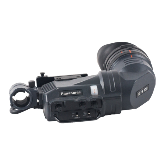
1.5-inch Electronic View Finder
2-inch Electronic View Finder
AJ-
AJ-
VQT0L51
P
E
P
E
日
本
語
Advertisement
Chapters
Table of Contents

Related Manuals for Panasonic AJ-VF20WBPE


Summary of Contents for Panasonic AJ-VF20WBPE
- Page 1 Operating Instructions 1.5-inch Electronic View Finder 2-inch Electronic View Finder Before operating this product, please read the instructions carefully and save this manual for future use. Bitte lesen Sie diese Bedienungsanleitung vor der Inbetriebnahme dieses Produkts aufmerksam durch, und bewahren Sie sie für späteres Nachschlagen auf. Avant d’utiliser l’appareil, lire attentivement ce mode d’emploi, et le conserver à...
- Page 2 Precautions for Use (General) WARNING: • TO REDUCE THE RISK OF FIRE OR SHOCK HAZARD, DO NOT EXPOSE THIS EQUIPMENT TO RAIN OR MOISTURE. • TO REDUCE THE RISK OF FIRE OR SHOCK HAZARD, KEEP THIS EQUIPMENT AWAY FROM ALL LIQUIDS. USE AND STORE ONLY IN LOCATIONS WHICH ARE NOT EXPOSED TO THE RISK OF DRIPPING OR SPLASHING LIQUIDS, AND DO NOT PLACE ANY LIQUID CONTAINERS ON TOP OF THE EQUIPMENT.
-
Page 3: Table Of Contents
Precautions for Use (For USA) FCC Note: This equipment has been tested and found to comply with the limits for a class A digital device, pursuant to Part 15 of the FCC Rules. These limits are designed to provide reasonable protection against harmful interference when the equipment is operated in a commercial environment. -
Page 4: Features
Features O The high-resolution CRT delivers superb picture sharpness, making focusing easier. O The low-flare CRT makes the screen clear and easy on the eyes. O The large eyepiece aperture makes it possible to see the screen even when holding the viewfinder at some distance from your eye. - Page 5 Parts and Their Functions PEAKING Knob Adjusts the outlines of the images in the viewfinder to make focusing easier. The setting of this control has no effect on the output signal of the camera. CONTRAST Knob Adjusts the contrast of the screen inside the viewfinder. The setting of this control has no effect on the output signal of the camera.
- Page 6 Parts and Their Functions Internal LEDs The lamp and picture tube indications will differ depending on the camera used with the viewfinder. Refer to the instruction manual of the camera for details. TALLY / REC TALLY / REC BATT BATT SAVE SAVE 4 : 3 Display...
-
Page 7: For Cameras Compatible With The Standard Slide Rail
For cameras compatible with the standard slide rail Camera model number NTSC regions PAL regions AJ-SPX800, AJ-SDX900, AJ-SDC905, AJ-SDC615 AJ-SPX800, AJ-SPX900, AJ-SDX900, AJ-D908, AJ-SDC905, AJ-D913, AJ-SDC615, AJ-D615 Mounting the Viewfinder Confirm that the POWER switch of the camera is “OFF”. Insert the plug into the connection jack of the viewfinder. -
Page 8: Adjusting The Viewfinder's Left-Right Position
For cameras compatible with the standard slide rail Adjusting the viewfinder’s left-right position Loosen the viewfinder left-right position anchoring ring. Slide the viewfinder to the left or right, and adjust it to a position that allows easy viewing. Viewfinder left-right Tighten the ring. -
Page 9: Detaching The Viewfinder
For cameras compatible with the standard slide rail Detaching the Viewfinder Confirm that the POWER switch of the camera is “OFF”. Loosen the viewfinder left-right position anchoring ring. While pulling up the viewfinder stopper, remove the viewfinder by sliding it in the direction of the arrow. -
Page 10: Diopter Adjustment
For cameras compatible with the standard slide rail Diopter Adjustment Set the POWER switch of the camera to “ON”. A picture will appear in the viewfinder. Turn the diopter adjustment ring to adjust the diopter so that the viewfinder picture can be clearly seen. -
Page 11: Detaching The Eyepiece
For cameras compatible with the standard slide rail Detaching the Eyepiece If dust has adhered to the CRT screen or mirror, detach the eyepiece and remove it. <Note> Do not wipe the mirror surface under any circumstances as it has been specially treated. Dust which has adhered to the mirror should be blown away with a blower, etc. -
Page 12: Mounting The Microphone
Mounting the Microphone Follow the steps below to install the AJ-MC700P microphone kit (sold separately). Open the microphone holder. Viewfinder Microphone holder Mount the microphone. Plug the microphone connector cable into the MIC IN jack. MIC IN jack 12 (E) -
Page 13: For Cameras Compatible With The Mounting Unit
For cameras compatible with the mounting unit Adjusting the Mounting Height of the Viewfinder The mounting height of the viewfinder will differ depending on the camera on which it is mounted. Adjust the mounting height to match the camera on which the viewfinder is to be mounted. -
Page 14: Mounting The Viewfinder
For cameras compatible with the mounting unit Mounting the Viewfinder Confirm that the POWER switch of the camera is “OFF”. Insert the plug into the connection jack of the viewfinder. <Note> Be sure to insert the plug all the way into the connection jack. Push the viewfinder down into place. -
Page 15: Position Adjustment
For cameras compatible with the mounting unit Position Adjustment Lift up the viewfinder forward-backward/left-right position clamp lever to disengage the lock. Lever Viewfinder Loosen the viewfinder forward-backward/left-right position clamp lever. Adjust the position of the viewfinder by moving it forward, backward, left or right. Return the viewfinder forward-backward/left-right position clamp lever to the locked position. -
Page 16: Specifications
Specifications Power supply: DC 12 V (supplied by camera) Power consumption: 2.1 W (AJ-VF15BP, AJ-VF15BE) 2.7 W (AJ-VF20WBP, AJ-VF20WBE) Picture tube: 1.5-inch high-resolution monochrome picture tube (AJ-VF15BP, AJ-VF15BE) 2-inch high-resolution monochrome picture tube (AJ-VF20WBP, AJ-VF20WBE) Horizontal resolution: 600 lines (center, typical, 4 : 3 mode) Image system: 525 lines, 60 fields (AJ-VF15BP, AJ-VF20WBP) 625 lines, 50 fields (AJ-VF15BE, AJ-VF20WBE) - Page 17 Memo...
- Page 18 Vorsichtsmaßnahmen WARNUNG: • ZUR REDUZIERUNG DER GEFAHR VON BRAND UND ELEKTRISCHEM SCHLAG DIESES GERÄT WEDER NÄSSE NOCH FEUCHTIGKEIT AUSSETZEN. • UM BRAND- ODER STROMSCHLAGGEFAHR ZU REDUZIEREN, MUSS DIESES GERÄT VON ALLEN FLÜSSIGKEITEN FERNGEHALTEN WERDEN. VERMEIDEN SIE GEBRAUCH UND LAGERUNG DES GERÄTES AN ORTEN, AN DENEN DIE GEFAHR BESTEHT, DASS ES MIT FLÜSSIGKEITEN BETROPFT ODER...
- Page 19 Inhalt Merkmale ............. 4 Teile und ihre Funktionen .
-
Page 20: Merkmale
Merkmale O Die hochauflösende Kathodenstrahlröhre liefert eine überragende Bildschärfe und erleichtert die Scharfeinstellung. O Die geringe Elektronenstreuung der Kathodenstrahlröhre sorgt für ein scharfes Bild zur ermüdungsfreien Betrachtung. O Die große Okularöffnung ermöglicht die Betrachtung des Sucherschirms selbst aus größerer Entfernung vom Auge. O Das Okular läßt sich leicht abnehmen. - Page 21 Teile und ihre Funktionen Konturregler [PEAKING] Dient zur Einstellung der Bildkonturen im Sucher, um die Scharfeinstellung zu erleichtern. Die Einstellung dieses Reglers hat keinen Einfluß auf das Ausgangssignal der Kamera. Kontrastregler [CONTRAST] Dient zur Einstellung des Sucherschirmkontrastes. Die Einstellung dieses Reglers hat keinen Einfluß...
- Page 22 Teile und ihre Funktionen Interne LEDs Die Lampen und Bildröhrenanzeigen hängen von der mit dem Sucher verwendeten Kamera ab. Einzelheiten sind der Bedienungsanleitung der Kamera zu entnehmen. TALLY / REC TALLY / REC BATT BATT SAVE SAVE Anzeigemodus 4 : 3 Anzeigemodus 16 : 9 AJ-VF15BP, AJ-VF15BE AJ-VF20WBP, AJ-VF20WBE...
-
Page 23: Für Kameras, Die Mit Der Standard-Gleitschiene Kompatibel Sind
Für Kameras, die mit der Standard-Gleitschiene kompatibel sind Kamera-Modellnummer NTSC-Gebiete PAL-Gebiete AJ-SPX800, AJ-SDX900, AJ-SDC905, AJ-SDC615 AJ-SPX800, AJ-SPX900, AJ-SDX900, AJ-D908, AJ-SDC905, AJ-D913, AJ-SDC615, AJ-D615 Anbringen des Suchers Sicherstellen, daß sich der Schalter POWER der Kamera in der AUS-Stellung befindet. Den Stecker in die Anschlußbuchse des Suchers einführen. <Hinweis>... -
Page 24: Einstellen Der Querposition Des Suchers
Für Kameras, die mit der Standard-Gleitschiene kompatibel sind Einstellen der Querposition des Suchers Lösen Sie den Querpositions-Feststellring des Suchers. Schieben Sie den Sucher nach links oder rechts, um seine Position so einzustellen, dass der Suchermonitor bequem ablesbar ist. Sucher-Querpositions- Den Ring anziehen. Feststellring Ziehen Sie den Querpositions-Feststellring des Suchers an. -
Page 25: Abnehmen Des Suchers
Für Kameras, die mit der Standard-Gleitschiene kompatibel sind Abnehmen des Suchers Confirm that the POWER switch of the camera is “OFF”. Lösen Sie den Querpositions-Feststellring des Suchers. Entfernen Sie den Sucher durch Schieben in Pfeilrichtung, während Sie den Sucheranschlag hochziehen. Den Ring anziehen. -
Page 26: Dioptrieneinstellung
Für Kameras, die mit der Standard-Gleitschiene kompatibel sind Dioptrieneinstellung Den Schalter POWER der Kamera auf die EIN-Stellung stellen. Ein Bild erscheint im Sucher. Das Okular durch Drehen des Dioptrien-Einstellrings so einstellen, daß das Sucherbild scharf ist. Dioptrien-Einstellring Sucherschirmeinstellung Den Zustand des Sucherschirms einstellen. Helligkeit: Den Regler BRIGHT drehen. -
Page 27: Abnehmen Des Okulars
Für Kameras, die mit der Standard-Gleitschiene kompatibel sind Abnehmen des Okulars Falls Staub an Sucherschirm oder Spiegel haftet, das Okular lösen und entfernen. <Hinweis> Die Spiegeloberfläche darf unter keinen Umständen abgewischt werden, da sie speziell vergütet ist. Am Spiegel haftender Staub sollte mit einem Blasepinsel oder dergleichen entfernt werden. -
Page 28: Anbringen Des Mikrofons
Anbringen des Mikrofons Führen Sie die folgenden Schritte aus, um den Mikrofonsatz AJ-MC700P (getrennt erhältlich) zu montieren. Den Mikrofonhalter öffnen. Sucher Mikrofonhalter Das Mikrofon anbringen. Den Stecker des Mikrofonkabels an die Buchse MIC IN anschließen. Buchse MIC IN 12 (D) -
Page 29: Für Kameras, Die Mit Der Montageeinheit Kompatibel Sind
Für Kameras, die mit der Montageeinheit kompatibel sind Einstellen der Montagehöhe des Suchers Die Montagehöhe des Suchers hängt von der Kamera ab, an die der Sucher angebracht wird. Die Montagehöhe des Suchers auf die zu verwendende Kamera einstellen. O Bitte wenden Sie sich bezüglich des Kaufs der Montageeinheit (VYQ1818) als Ersatzteil an Ihren Händler. -
Page 30: Anbringen Des Suchers
Für Kameras, die mit der Montageeinheit kompatibel sind Anbringen des Suchers Sicherstellen, daß sich der Schalter POWER der Kamera in der AUS-Stellung befindet. Den Stecker in die Anschlußbuchse des Suchers einführen. <Hinweis> Führen Sie den Stecker bis zum Anschlag in die Anschlußbuchse ein. Den Sucher nach unten andrücken. -
Page 31: Positionseinstellung
Für Kameras, die mit der Montageeinheit kompatibel sind Positionseinstellung Den Sucherpositions-Feststellhebel anheben, um die Verriegelung freizugeben. Hebel Sucher Den Sucherpositions-Feststellhebel lösen. Die Position des Suchers durch Verschieben in die gewünschte Richtung einstellen. Den Sucherpositions-Feststellhebel wieder auf die Verriegelungsstellung zurückstellen. 15 (D) -
Page 32: Technische Daten
Technische Daten Stromversorgung: 12 V Gleichspannung (Versorgung durch Kamera) Leistungsaufnahme: 2,1 W (AJ-VF15BP, AJ-VF15BE) 2,7 W (AJ-VF20WBP, AJ-VF20WBE) Bildröhre: Hochauflösende 1,5-Zoll-Schwarzweiß-Bildröhre (AJ-VF15BP, AJ-VF15BE) Hochauflösende 2-Zoll-Schwarzweiß-Bildröhre (AJ-VF20WBP, AJ-VF20WBE) Horizontalauflösung: 600 Zeilen (Mitte, typisch, Modus 4 : 3) Bildsystem: 525 Zeilen, 60 Halbbilder (AJ-VF15BP, AJ-VF20WBP) 625 Zeilen, 50 Halbbilder (AJ-VF15BE, AJ-VF20WBE) Externe Regler: Regler (BRIGHT, CONTRAST, PEAKING) - Page 33 Notizen...
- Page 34 Précautions à prendre AVERTISSEMENT: • POUR RÉDUIRE LES RISQUES D’INCENDIE OU DE CHOC ÉLECTRIQUE, ÉVITEZ D’EXPOSER CET APPAREIL À LA PLUIE OU À L’HUMIDITÉ. • POUR RÉDUIRE TOUT RISQUE DE FEU OU DE CHOC ÉLECTRIQUE, ÉLOIGNER L’APPAREIL DES LIQUIDES - UTILISER ET RANGER UNIQUEMENT DANS UN ENDROITNE RISQUANT PAS DE RECEVOIR DES GOUTTES OU D’ÊTRE ASPERGÉ...
- Page 35 Table des matières Caractéristiques ............4 Les commandes et leurs fonctions .
-
Page 36: Caractéristiques
Caractéristiques O Le tube cathodique à haute résolution délivre une extraordinaire netteté d’image, ce qui facilite la mise au point. O Le tube cathodique à faible lumière parasite rend l’écran plus facile à voir et moins fatiguant pour les yeux. O La grosse ouverture de l’œilleton permet de voir l’écran même en éloignant le viseur de l’œil. - Page 37 Les commandes et leurs fonctions Bouton de crête (PEAKING) Il permet de régler les contours de l’image dans le viseur de façon à les rendre plus nets. Le réglage de cette commande est sans effet sur le signal de sortie de la caméra. Bouton de contraste (CONTRAST) Il permet de régler le contraste de l’écran dans le viseur.
- Page 38 Les commandes et leurs fonctions LED internes Les indications du tube image et des voyants varient en fonction de la caméra utilisée avec le viseur. Pour les détails, voir le mode d’emploi de la caméra. TALLY / REC TALLY / REC BATT BATT SAVE...
-
Page 39: Pour Les Caméras Compatibles Avec Le Rail Coulissant Standard
Pour les caméras compatibles avec le rail coulissant standard No. de modèle de la caméra Régions NTSC Régions PAL AJ-SPX800, AJ-SDX900, AJ-SDC905, AJ-SDC615 AJ-SPX800, AJ-SPX900, AJ-SDX900, AJ-D908, AJ-SDC905, AJ-D913, AJ-SDC615, AJ-D615 Montage du viseur Vérifier que l’interrupteur POWER de la caméra est éteint (“OFF”). Insérer la fiche dans la prise de raccordement du viseur. -
Page 40: Réglage De La Position Gauche-Droite Du Viseur
Pour les caméras compatibles avec le rail coulissant standard Réglage de la position gauche-droite du viseur Desserrer la bague d’ancrage de la position gauche-droite du viseur. Glisser le viseur vers la gauche ou vers la droite, et le régler sur la position permettant une vue facile des données sur l’écran. -
Page 41: Retrait Du Viseur
Pour les caméras compatibles avec le rail coulissant standard Retrait du viseur Vérifier que l’interrupteur POWER de la caméra est éteint (“OFF”). Desserrer la bague d’ancrage de la position gauche-droite du viseur. Tout en soulevant la butée du viseur, retirer le viseur en le glissant dans le sens de la flèche. -
Page 42: Réglage De La Correction Dioptrique
Pour les caméras compatibles avec le rail coulissant standard Réglage de la correction dioptrique Mettre l’interrupteur POWER de la caméra sur “ON”. Une image apparaît dans le viseur. Tourner la bague de correction dioptrique de façon que l’image du viseur soit nette. Bague de correction dioptrique Réglage de l’écran Régler les conditions de l’écran du viseur. -
Page 43: Retrait De L'œilleton
Pour les caméras compatibles avec le rail coulissant standard Retrait de l’œilleton Si de la poussière colle au tube image ou au miroir, détacher l’œilleton et le retirer. <Remarque> En aucun cas on n’essuiera la surface du miroir, car elle a été spécialement traitée. La poussière qui colle au miroir devra être enlevée avec une poire soufflante, par exemple. -
Page 44: Montage Du Microphone
Montage du microphone Pour monter le microphone AJ-MC700P (vendu séparément), procéder de la façon suivante. Ouvrir le support du microphone. Viseur Support de microphone Monter le microphone. Brancher le câble de raccordement du microphone dans la prise MIC IN. Prise MIC IN 12 (F) -
Page 45: Pour Les Caméras Compatibles Avec Le Module De Montage
Pour les caméras compatibles avec le module de montage Réglage de la hauteur de montage du viseur La hauteur de montage du viseur varie en fonction de la caméra sur laquelle le viseur est monté. Régler la hauteur de montage en fonction de la caméra sur laquelle le viseur est monté. O Pour l’achat du module de montage (VYQ1818), consulter son revendeur car il s’agit d’une pièce de rechange. -
Page 46: Montage Du Viseur
Pour les caméras compatibles avec le module de montage Montage du viseur Vérifier que l’interrupteur POWER de la caméra est éteint (“OFF”). Insérer la fiche dans la prise de raccordement du viseur. <Remarque> Bien insérer la fiche à fond dans la prise de raccordement. Enfoncer le viseur en place. -
Page 47: Réglage De La Position
Pour les caméras compatibles avec le module de montage Réglage de la position Soulever le levier de serrage de position avant-arrière/gauche-droite du viseur de façon à dégager le verrouillage. Levier Viseur Desserrer le levier de serrage de position avant-arrière/gauche-droite du viseur. Régler la position du viseur en le déplaçant vers l’avant, l’arrière, la gauche ou la droite. -
Page 48: Fiche Technique
Fiche technique Alimentation: CC 12 V (fournie par la caméra) Consommation: 2,1 W (AJ-VF15BP, AJ-VF15BE) 2,7 W (AJ-VF20WBP, AJ-VF20WBE) Tube image: Tube image monochrome haute résolution de 1,5 pouce (AJ-VF15BP, AJ-VF15BE) Tube image monochrome haute résolution de 2,0 pouce (AJ-VF20WBP, AJ-VF20WBE) Définition horizontale: 600 lignes (centre, type, mode 4 : 3) Système image:... - Page 49 Mémo...
- Page 50 Precauzioni per l’uso ATTENZIONE: • PER RIDURRE IL RISCHIO D’INCENDIO O DI SCOSSE, NON ESPORRE QUESTO PRODOTTO ALLA PIOGGIA O ALL’UMIDITÀ. • PER RIDURRE IL RISCHIO D’INCENDIO O DI SCOSSE ELETTRICHE, TENERE QUESTO PRODOTTO LONTANO DA TUTTI I LIQUIDI. USARLO E CONSERVARLO SOLTANTO IN LUOGHI CHE NON SIANO ESPOSTI A GOCCIOLAMENTI O SPRUZZI DI LIQUIDI, E NON METTERVI SOPRA RECIPIENTI DI LIQUIDI.
- Page 51 Sommario Caratteristiche ............4 Parti e loro funzioni .
-
Page 52: Caratteristiche
Caratteristiche O Il CRT ad alta risoluzione produce una superba nitidezza delle immagini che rende più facile la messa a fuoco. O Il CRT a basso riflesso rende lo schermo chiaro e non affatica gli occhi. O La grande apertura dell’oculare consente di vedere lo schermo anche tenendo il mirino ad una certa distanza dagli occhi. - Page 53 Parti e loro funzioni Manopola PEAKING Regola i contorni delle immagini nel mirino per facilitare la messa a fuoco. La regolazione di questo controllo non ha alcun effetto sul segnale di uscita della videocamera. Manopola CONTRAST Regola il contrasto dello schermo all’interno del mirino. La regolazione di questo controllo non ha alcun effetto sul segnale di uscita della videocamera.
- Page 54 Parti e loro funzioni LED interni Le spie e le indicazioni del cinescopio differiscono secondo la videocamera usata con il mirino. Per i dettagli, riferirsi al manuale di istruzioni della videocamera. TALLY / REC TALLY / REC BATT BATT SAVE SAVE Display 4 : 3 Display 16 : 9...
-
Page 55: Videocamere Compatibili Con La Rotaia Di Scorrimento Standard
Videocamere compatibili con la rotaia di scorrimento standard Modello videocamera Sistema NTSC Sistema PAL AJ-SPX800, AJ-SDX900, AJ-SDC905, AJ-SDC615 AJ-SPX800, AJ-SPX900, AJ-SDX900, AJ-D908, AJ-SDC905, AJ-D913, AJ-SDC615, AJ-D615 Montaggio del mirino Accertarsi che l’interruttore POWER della videocamera sia posizionato su “OFF”. Inserire la spina nella presa di connessione del mirino. <Nota>... -
Page 56: Regolazione Della Posizione Destra/Sinistra Del Mirino
Videocamere compatibili con la rotaia di scorrimento standard Regolazione della posizione destra/sinistra del mirino Allentare l’anello di ancoraggio posizione destra/sinistra mirino. Spingere il mirino a destra o a sinistra, e regolarlo su una posizione che permetta una comoda visione. Anello di ancoraggio posizione Stringere l’anello. -
Page 57: Modo Di Staccare Il Mirino
Videocamere compatibili con la rotaia di scorrimento standard Modo di staccare il mirino Accertarsi che l’interruttore POWER della videocamera sia posizionato su “OFF”. Allentare l’anello di ancoraggio posizione destra/sinistra mirino. Tirando su il fermo mirino, rimuovere il mirino spingendolo nella direzione della freccia. -
Page 58: Regolazione Delle Diottrie
Videocamere compatibili con la rotaia di scorrimento standard Regolazione delle diottrie Posizionare l’interruttore POWER della videocamera su “ON”. Sul mirino appaiono le immagini. Girare l’anello di regolazione diottrie per regolare le diottrie in modo da vedere chiaramente le immagini sul mirino. Anello di regolazione diottrie Regolazione dello schermo Regolare la condizione dello schermo del mirino. -
Page 59: Modo Di Staccare L'oculare
Videocamere compatibili con la rotaia di scorrimento standard Modo di staccare l’oculare Se sullo schermo CRT o sullo specchio c’è della polvere, staccare l’oculare per toglierla. <Nota> Non si deve assolutamente strofinare la superficie dello specchio, perché è trattata in modo speciale. -
Page 60: Montaggio Del Microfono
Montaggio del microfono Per installare il kit del microfono AJ-MC700P (venduto separatamente), seguire il procedimento dei passi sotto. Aprire il supporto del microfono. Mirino Supporto microfono Montare il microfono. Attaccare il cavo connettore microfono alla presa MIC IN. Presa MIC IN 12 ( I ) -
Page 61: Videocamere Compatibili Con L'unità Di Montaggio
Videocamere compatibili con l’unità di montaggio Regolazione dell’altezza di montaggio del mirino L’altezza di montaggio del mirino differisce secondo la videocamera su cui viene montato. Regolare l’altezza di montaggio secondo la videocamera su cui viene montato. O Per l’acquisto dell’unità di montaggio (VYQ1818), rivolgersi al rivenditore riguardo ad essa come parte di ricambio. -
Page 62: Montaggio Del Mirino
Videocamere compatibili con l’unità di montaggio Montaggio del mirino Accertarsi che l’interruttore POWER della videocamera sia posizionato su “OFF”. Inserire la spina nella presa di connessione del mirino. <Nota> Inserire completamente la spina nella presa di connessione. Spingere giù il mirino in posizione. Stringere saldamente la vite di fermo. -
Page 63: Regolazione Della Posizione
Videocamere compatibili con l’unità di montaggio Regolazione della posizione Sollevare la leva di fissaggio posizione avanti-indietro/destra-sinistra mirino per rilasciare il bloccaggio. Leva Mirino Allentare la leva di fissaggio posizione avanti-indietro/destra-sinistra mirino. Regolare la posizione del mirino spostandolo in avanti-indietro, a destra o a sinistra. -
Page 64: Dati Tecnici
Dati tecnici Alimentazione: C.c. 12 V (fornita dalla videocamera) Assorbimento di corrente: 2,1 W (AJ-VF15BP, AJ-VF15BE) 2,7 W (AJ-VF20WBP, AJ-VF20WBE) Cinescopio: Cinescopio 1,5 pollici monocromatico ad alta risoluzione (AJ-VF15BP, AJ-VF15BE) Cinescopio 2 pollici monocromatico ad alta risoluzione (AJ-VF20WBP, AJ-VF20WBE) Risoluzione orizzontale: 600 righe (centro, tipica, modalità... - Page 65 Promemoria...
- Page 66 Precauciones para la utilización ADVERTENCIA: • PARA REDUCIR EL RIESGO DE PRODUCIR UN INCENDIO O RECIBIR UNA DESCARGA ELÉCTRICA, NO EXPONGA ESTE EQUIPO A LA LLUVIA NI A LA HUMEDAD. • PARA REDUCIR EL RIESGO DE INCENDIO O SACUDIDA ELÉCTRICA, MANTENGA ESTE EQUIPO ALEJADO DE TODOS LOS LÍQUIDOS.
- Page 67 Índice Características ............4 Partes y sus funciones .
-
Page 68: Características
Características O El tubo de rayos catódicos de alta definición suministra una extraordinaria nitidez de imagen, facilitando considerablemente el enfoque. O El tubo de rayos catódicos de poco brillo hace que la pantalla quede más clara y no se cansen los ojos. O La abertura grande del ocular permite ver la pantalla incluso cuando el visor se encuentra a cierta distancia del ojo. - Page 69 Partes y sus funciones Control PEAKING Ajusta los contornos de las imágenes en el visor para facilitar el enfoque. El ajuste de este control no tiene ningún efecto en las señales de salida de la videocámara. Control CONTRAST Ajusta el contraste de la pantalla en el interior del visor. El ajuste de este control no tiene ningún efecto en las señales de salida de la videocámara.
- Page 70 Partes y sus funciones LEDs internos La lámparas y las indicaciones del tubo de imagen cambiarán según la videocámara utilizada con el visor. Consulte el manual de instrucciones de la videocámara para tener detalles. TALLY / REC TALLY / REC BATT BATT SAVE...
-
Page 71: Para Cámaras Compatibles Con El Riel De Deslizamiento Estándar
Para cámaras compatibles con el riel de deslizamiento estándar Número de modelo de videocámara Regiones NTSC Regiones PAL AJ-SPX800, AJ-SDX900, AJ-SDC905, AJ-SDC615 AJ-SPX800, AJ-SPX900, AJ-SDX900, AJ-D908, AJ-SDC905, AJ-D913, AJ-SDC615, AJ-D615 Montaje del visor Confirme que el conmutador POWER de la videocámara esté en “OFF”. Inserte la clavija en la toma de conexión del visor. -
Page 72: Ajuste De La Posición Hacia La Derecha O Hacia La Izquierda Del Visor
Para cámaras compatibles con el riel de deslizamiento estándar Ajuste de la posición hacia la derecha o hacia la izquierda del visor Afloje el anillo de fijación de la posición hacia la derecha o hacia la izquierda del visor. Deslice el visor hacia la derecha o hacia la izquierda y ajústelo en una posición que permita ver su pantalla fácilmente. -
Page 73: Desmontaje Del Visor
Para cámaras compatibles con el riel de deslizamiento estándar Desmontaje del visor Confirme que el conmutador POWER de la videocámara esté en “OFF”. Afloje el anillo de fijación de la posición hacia la derecha o hacia la izquierda del visor. Mientras tira hacia arriba del tope del visor, retire el visor deslizándolo en el sentido de la flecha. -
Page 74: Ajuste De Dioptrías
Para cámaras compatibles con el riel de deslizamiento estándar Ajuste de dioptrías Ponga el conmutador POWER de la videocámara en “ON”. En el visor aparecerá una imagen. Gire el anillo de ajuste de dioptrías de forma que la imagen del visor pueda verse claramente. -
Page 75: Desmontaje Del Ocular
Para cámaras compatibles con el riel de deslizamiento estándar Desmontaje del ocular Si se ha adherido polvo a la pantalla o espejo del tubo de rayos catódicos, separe el ocular y quite el polvo. <Nota> No frote la superficie del espejo bajo ninguna circunstancia porque ha sido tratada especialmente. -
Page 76: Montaje Del Micrófono
Montaje del micrófono Siga los pasos de abajo para instalar el juego del micrófono AJ-MC700P (vendido por separado). Abra el soporte del micrófono. Visor Soporte del micrófono Monte el micrófono. Enchufe el cable del micrófono en la toma MIC IN. Toma MIC IN 12 (S) -
Page 77: Para Cámaras Compatibles Con La Unidad De Montaje
Para cámaras compatibles con la unidad de montaje Ajuste de la altura de montaje del visor La altura de montaje del visor cambiará según la videocámara en la que se monte. Ajuste la altura de montaje según la videocámara en la que se vaya a montar el visor. O Para adquirir la unidad de montaje (VYQ1818) consulte a su concesionario. -
Page 78: Montaje Del Visor
Para cámaras compatibles con la unidad de montaje Montaje del visor Confirme que el conmutador POWER de la videocámara esté en “OFF”. Inserte la clavija en la toma de conexión del visor. <Nota> Asegúrese de insertar a fondo la clavija en la toma de conexión. Empuje el visor hacia abajo para colocarlo en su lugar. -
Page 79: Ajuste De Posición
Para cámaras compatibles con la unidad de montaje Ajuste de posición Levante la palanca de fijación de posición hacia adelante-atrás/izquierda-derecha del visor para soltar el cierre. Palanca Visor Afloje la palanca de fijación de posición hacia adelante-atrás/izquierda-derecha del visor. Ajuste la posición del visor moviéndolo hacia adelante, atrás, izquierda o derecha. Vuelva a poner la palanca de fijación de posición hacia adelante-atrás/izquierda- derecha del visor en la posición de bloqueo. -
Page 80: Especificaciones
Especificaciones Alimentación: CC 12 V (suministrada por la videocámara) Consumo: 2,1 W (AJ-VF15BP, AJ-VF15BE) 2,7 W (AJ-VF20WBP, AJ-VF20WBE) Tubo de imagen: Tubo de imagen monocromo de alta definición de 1,5 pulgadas (AJ-VF15BP, AJ-VF15BE) Tubo de imagen monocromo de alta definición de 2 pulgadas (AJ-VF20WBP, AJ-VF20WBE) Definición horizontal: 600 líneas (centro, típica, modo 4 : 3) - Page 81 Apuntes...
- Page 82 • • 2 (C)
- Page 83 ..............4 .
- Page 84 6 > < ZEBRA ON : OFF : TALLY HIGH: OFF : LOW : 4 (C)
- Page 85 PEAKING CONTRAST BRIGHT TALLY HIGH TALLY HIGH < > 5 (C)
- Page 86 TALLY / REC TALLY / REC BATT BATT SAVE SAVE 4 : 3 16 : 9 AJ-VF15BP AJ-VF15BE AJ-VF20WBP AJ-VF20WBE 6 (C)
- Page 87 NTSC AJ-SPX800, AJ-SDX900, AJ-SDC905, AJ-SDC615 AJ-SPX800, AJ-SPX900, AJ-SDX900, AJ-D908, AJ-SDC905, AJ-D913, AJ-SDC615, AJ-D615 POWER < > 7 (C)
- Page 88 8 (C)
- Page 89 POWER 9 (C)
- Page 90 POWER BRIGHT CONTRAST PEAKING PEAKING CONTRAST BRIGHT PEAKING CONTRAST BRIGHT POWER OUTPUT BRIGHT CONTRAST PEAKING 10 (C)
- Page 91 < > LOCK 11 (C)
- Page 92 AJ-MC700P MIC IN MIC IN 12 (C)
- Page 93 (VYQ1818) NTSC AJ-D810, AJ-D810A, AJ-D900W, AJ-D900WA, AJ-D900W, AJ-D900WA, AJ-D910WA, AJ-D915WB AJ-D910WA, AJ-PD900W, AJ-PD900WA, AJ-SDC915 NTSC AJ-D700, AJ-D700A, AG-DVC200 AJ-D700, AJ-D700A, AJ-D800, AJ-D800A, AG-DVC200 NTSC AQ-23W AQ-23W 13 (C)
- Page 94 POWER < > POWER < > 14 (C)
- Page 95 15 (C)
- Page 96 DC 12V 2.1 W (AJ-VF15BP AJ-VF15BE) 2.7 W (AJ-VF20WBP AJ-VF20WBE) (AJ-VF15BP AJ-VF15BE) (AJ-VF20WBP AJ-VF20WBE) 4 : 3 (AJ-VF15BP AJ-VF20WBP) (AJ-VF15BE AJ-VF20WBE) (BRIGHT CONTRAST PEAKING) (TALLY HIGH/OFF/LOW ZEBRA ON/OFF) 206 mm 730 g (AJ-VF15BP AJ-VF15BE) 745 g (AJ-VF20WBP AJ-VF20WBE) 16 (C)
- Page 98 保証書別添付 製造番号は、品質管理上重要なものです。 製品本体と保証書の製造番号をお確かめください。 ご注意 本機内部には、高電圧部があります。絶対に開けないようにお願いいたします。 アイピースを太陽に向けないように注意してください。 目 次 安全上のご注意 . . . . . . . . . . . . . . . . . . . . . . . . . . . . . . . . . . . . . . . . . . . . . . . . . . . . . 3 特 長 . . . . . . . . . . . . . . . . . . . . . . . . . . . . . . . . . . . . . . . . . . . . . . . . . . . . . . . . . . . . 9 各部の名称と機能 . . . . . . . . . . . . . . . . . . . . . . . . . . . . . . . . . . . . . . . . . . . . . . . . . . . . 9 標準スライドレール対応カメラの場合 . . . . . . . . . . . . . . . . . . . . . . . . . . . . . . . . . . . . 12 ビューファインダーの取り付け . . . . . . . . . . . . . . . . . . . . . . . . . . . . . . . . . . . . . . . 12 ビューファインダーの左右位置調整 . . . . . . . . . . . . . . . . . . . . . . . . . . . . . . . . . . . 13 ビューファインダーの前後位置調整 . . . . . . . . . . . . . . . . . . . . . . . . . . . . . . . . . . . 13 ビューファインダーの取り外し . . . . . . . . . . . . . . . . . . . . . . . . . . . . . . . . . . . . . . 14 視度調整 . . . . . . . . . . . . . . . . . . . . . . . . . . . . . . . . . . . . . . . . . . . . . . . . . . . . . . . 15 画面調整 . . . . . . . . . . . . . . . . . . . . . . . . . . . . . . . . . . . . . . . . . . . . . . . . . . . . . . . 15 アイピースの取り外し . . . . . . . . . . . . . . . . . . . . . . . . . . . . . . . . . . . . . . . . . . . . . 16 マイクを取り付ける...
-
Page 99: 安全上のご注意
安全上のご注意 必ずお守りください お使いになる人や他の人への危害、財産への損害を未然に防止するため、必ずお 守りいただくことを、次のように説明しています。 ■表示内容を無視して誤った使い方をしたときに生じる危害や損害の程度を、次 の表示で区分し、説明しています。 この表示の欄は、 「死亡または重傷などを負う可能性が想定され 警告 る」内容です。 この表示の欄は、 「傷害を負う可能性または物的損害のみが発生 注意 する可能性が想定される」内容です。 ■お守りいただく内容の種類を、次の絵表示で区分し、説明しています。 (下記 は、絵表示の一例です。 ) このような絵表示は、気をつけていただきたい「注意喚起」内容 です。 このような絵表示は、してはいけない「禁止」内容です。 このような絵表示は、必ず実行していただく「強制」内容です。 日 本 語 3 (J) - Page 100 安全上のご注意 必ずお守りください 警告 設置について ■水場に設置しない! ■不安定な場所に置かない! 落 ち た り 、 倒 れ た り 火災・感電の原因 となります。 し て け が の 原 因 と な ります。 水場使用禁止 禁 止 ■ぬれた手で、プラグの抜き ■確実に固定する 差しはしない! 外れると、落下したり してけがの原因となり 感 電 の 原 因 と な り ま ます。...
- Page 101 安全上のご注意 必ずお守りください 警告 使用方法について ■本機を改造しない! ■水場で使用しない! 火災・感電の原因と 火災・感電の原因と なります。 なります。 水場使用禁止 分 解 禁 止 ■本機の裏ぶた・キャビネッ ■機器が濡れたり、水が入 ト ・ カ バ ー な ど を 外 さ な らないようにする! い! 火 災 ・ 感 電 の お そ れ があります。 感電の原因となりま...
- Page 102 安全上のご注意 必ずお守りください 警告 異常時の処理について ■本機を落としたり、破損し ■本機の内部に水などが入 た場合は、プラグを抜く! っ た 場 合 は 、 プ ラ グ を 抜 く! そ の ま ま 使 用 す る そ の ま ま 使 用 す る と、火災・感電を起 と 、 火 災 ・ 感 電 を こすおそれがありま...
- Page 103 安全上のご注意 必ずお守りください 注意 設置について ■ぬれた手でプラグを抜き ■油煙や湯気が当たる場所に 差ししない! 置かない! 火災・感電の原因とな 感電の原因となるこ ることがあります。 とがあります。 禁 止 禁 止 ■湿気やほこりの多い場所に ■プラグを抜くときは、コ 置かない! ードを引っ張らない! 火災・感電の原因とな コードが傷つき、火 ることがあります。 災・感電の原因とな ることがあります。 禁 止 禁 止 O 必ずプラグを持って抜いてくださ い。 日 本 語 7 (J)
- Page 104 安全上のご注意 必ずお守りください 注意 使用方法について ■本機の上に重い物を置かな ■本機に乗らない! い! バランスがくずれて、 倒れたり、壊れたり 落下し、けがの原因と し、けがの原因にな なります。 ります。 禁 止 禁 止 注意 お手入れについて ■お手入れの際は安全のため、 ■1 年に 1 度ぐらいは、販 プラグを抜く! 売店に内部の掃除の相談 を! 火災・感電の原因と 本機の内部にほこり な る こ と が あ り ま がたまったまま、使 す。 用 し 続 け る と 、 火 災・故障の原因とな...
-
Page 105: 特 長
特 長 O 高解像度 CRT が、きめ細かな画像を映し出し、フォーカス操作を容易に行うことがで きます。 O 低フレアの CRT を採用していますので、画面が見やすくなっています。 O 大口径ですので、目を離しても画面は見やすくなっています。 O アイピース部を容易に脱着できます。 O ワンタッチで左右だけでなく、前後にも位置を調節できます。 各部の名称と機能 6 > < ZEBRA (ゼブラパターン) スイッチ ビューファインダー内にゼブラパターンを表示させます。 ON : ゼブラパターンを表示させます。 OFF : ゼブラパターンは表示されません。 ゼブラパターンの種類など表示内容は、組み合わせるカメラによって異なりま す。詳しくは、カメラの取扱説明書をご覧ください。 TALLY スイッチ フロントタリーランプを設定します。 HIGH :フロントタリーランプが明るくなります。 OFF : フロントタリーランプが消灯します。 日 LOW : フロントタリーランプが暗くなります。 本... - Page 106 各部の名称と機能 PEAKING (ピーキング) つまみ ピントを合わせやすくするために、ビューファインダー内の映像の輪郭を調整します。 カメラの出力信号には影響ありません。 CONTRAST (濃淡) つまみ ビューファインダー内の画面の濃淡を調整します。 カメラの出力信号には影響ありません。 BRIGHT (明るさ) つまみ ビューファインダー内の画面の明るさを調整します。 カメラの出力信号には影響ありません。 フロントタリーランプ TALLY スイッチが「HIGH」または「LOW」の位置のときに動作し、撮影中に点灯し ます。また、ビューファインダー内の REC ランプと同様に点滅し、警告表示も行いま す。 点灯時の明るさは、TALLY スイッチ (HIGH または LOW) で切り替えることができま す。 ビューファインダーストッパー ビューファインダーの取り付け、取り外しに使用します。 アイピース バックタリーランプ 撮影中に点灯します。また、ビューファインダー内の REC ランプと同様に点滅し、警 告表示も行います。 レバーを OFF 側にすると、バックタリーランプが隠れます。 視度調整リング カメラマンの視度に合わせて、ビューファインダー画面上の映像が最もはっきり見え るように調整します 接続プラグ < ロックリング...
- Page 107 各部の名称と機能 内部 LED 各ランプやブラウン管の表示内容は、組み合わせるカメラによって異なります。 詳しくは、カメラの取扱説明書をご覧ください。 TALLY / REC TALLY / REC BATT BATT SAVE SAVE 4:3 表示 16:9 表示 AJ-VF15BP、 AJ-VF20WBP、 AJ-VF15BE AJ-VF20WBE 日 本 語 11 (J)
-
Page 108: 標準スライドレール対応カメラの場合
標準スライドレール対応カメラの場合 カメラのモデル No. NTSC エリア PAL エリア AJ-SPX800、AJ-SDX900、AJ-SDC905、 AJ-SPX800、AJ-SPX900、AJ-SDX900、 AJ-SDC615 AJ-D908、AJ-SDC905、AJ-D913、 AJ-SDC615、AJ-D615 ビューファインダーの取り付け カメラの POWER スイッチが「OFF」であることを確認します。 ビューファインダー接続端子にプラグを接続します。 < ノート > ビューファインダー接続端子にプラグを接続するときはしっかり確実に押し込ん でください。 ゆるめる ビューファインダー左右位置固定リングをゆるめます。 ビューファインダーストッパーを引き上げながら、ビューファインダーを矢印の 方向へスライドさせて取り付けます。 ビューファインダー ストッパー ビューファインダー左右位置固定リングを締めます。 12 (J) -
Page 109: ビューファインダーの左右位置調整
標準スライドレール対応カメラの場合 ビューファインダーの左右位置調整 ビューファインダー左右位置固定リングをゆるめます。 ビューファインダーを左右にスライドさせ、見やすい位置に調整します。 ビューファインダー 締める 左右位置固定リング ビューファインダー左右位置固定リングを締めます。 ビューファインダーの前後位置調整 ビューファインダー前後位置固定レバーをゆるめます。 ビューファインダーを前後にスライドさせ、見やすい位置に調整します。 ビューファインダー前後位置固定レバー 日 ビューファインダー前後位置固定レバーを締めます。 本 語 13 (J) -
Page 110: ビューファインダーの取り外し
標準スライドレール対応カメラの場合 ビューファインダーの取り外し カメラの POWER スイッチが「OFF」であることを確認します。 ビューファインダー左右位置固定リングをゆるめます。 ビューファインダーストッパーを引き上げながら、ビューファインダーを矢印の 方向へスライドして取り外します。 ゆるめる ビューファインダー ストッパー ビューファインダーケーブルとマイクケーブルをクランプから外し、それぞれの ケーブルを抜きます。 14 (J) -
Page 111: 視度調整
標準スライドレール対応カメラの場合 視度調整 カメラの POWER スイッチを「ON」にします。ビューファインダーに画像がみ えます。 視度調整リングを回して、ビューファインダーの画像がはっきり見えるように調 整します。 視度調整リング 画面調整 ビューファインダーの画面の状態を調整します。 明るさ:BRIGHT つまみで調整します。 濃 淡:CONTRAST つまみで調整します。 輪 郭:PEAKING つまみで調整します。 PEAKING CONTRAST BRIGHT PEAKING つまみ CONTRAST つまみ BRIGHT つまみ カメラの POWER スイッチを「ON」にします。 カメラの OUTPUT スイッチを「BAR」にします。 ビューファインダーの BRIGHT と CONTRAST つまみを回して、画像の明るさ とコントラストを調整します。 PEAKING つまみを回すと、画像をよりシャープに調整できます。 シャープにすると、レンズでのピント合わせがやり易くなります。 日... -
Page 112: アイピースの取り外し
標準スライドレール対応カメラの場合 アイピースの取り外し CRT 画面やミラーにほこりが付着した場合、アイピースを取り外して除去してください。 < ノート > ミラーは表面に特殊処理をほどこしていますので、絶対にふかないでください。ほこりが 付着した時はブロワなどで、ふき飛ばしてください。 合いマーク アイピース ロックリングを時計と反対方向にいっ ぱいに回し、ロックリングとビューフ ァインダーの筒の合いマークを合わせ ロックリング ます。 アイピースを抜き取ります。 再び取りつけるには 1 ロックリングの合いマークをビューファインダーの筒の合いマークに合わせ、アイ ピースを差し込みます。 2 ロックリングを時計方向に、 の位置まで確実に回してください。 LOCK 16 (J) -
Page 113: マイクを取り付ける
マイクを取り付ける マイクキット AJ-MC700P(別売品)のマイクを取りつけることができます。 マイクホルダーを開きます。 ビューファインダー マイクホルダー マイクを取りつけます。 マイクの接続ケーブルをカメラの MIC IN 端子に接続します。 MIC IN 端子 日 本 語 17 (J) -
Page 114: 取り付けユニット対応カメラの場合
取り付けユニット対応カメラの場合 取り付け高さの設定 ビューファインダーの取り付け高さは、組み合わせるカメラによって異なります。 組み合わせるカメラに応じて、取り付けユニットの高さを変更してください。 O 取り付けユニット(VYQ1818)をお求めになる場合は、補修部品としてお買い上げの販売店にお申し付け ください。 カメラのモデル No. 取り付け位置 NTSC エリア PAL エリア AJ-D810、AJ-D810A、 AJ-D900W、AJ-D900WA、 出荷時の位置 AJ-D900W、AJ-D900WA、 AJ-D910WA、AJ-D915WB 取り付け高さの変更は不要 AJ-D910WA、AJ-PD900W、 です。 AJ-PD900WA、AJ-SDC915 NTSC エリア PAL エリア A の位置に変更 AJ-D700、AJ-D700A、 AJ-D700、AJ-D700A、 AG-DVC200 AJ-D800、AJ-D800A、AG-DVC200 NTSC エリア PAL エリア B の位置に変更 AQ-23W AQ-23W O 取り付けユニットの高さ変更... -
Page 115: ビューファインダーの取り付け
取り付けユニット対応カメラの場合 ビューファインダーの取り付け カメラの POWER スイッチが「OFF」であることを確認します。 ビューファインダー接続端子にプラグを接続します。 < ノート > ビューファインダー接続端子にプラグを接続するときはしっかり確実に押し込ん でください。 ビューファインダーを押し下げます。 ストッパーネジを確実に締めます。 ストッパーねじ ビューファインダーの取り外し カメラの POWER スイッチが「OFF」であることを確認します。 ストッパーネジを緩め、ビューファインダーを真上に引き上げて、抜き取ります。 < ノート > ビューファインダーを抜き取る時は、両手で行ってください。片手ではスムーズ に取り外すことができない場合があり、またファインダーが破損するおそれがあ ります。 ビューファインダーケーブル端子からプラグを抜き取ります。 ストッパーねじ 日 本 語 19 (J) -
Page 116: 位置調整
取り付けユニット対応カメラの場合 位置調整 ビューファインダー前後左右位置固定レバーを引き上げるとロックがはずれます。 レバー ビューファインダー 前後左右位置固定レバーをゆるめます。 ビューファインダーを前後左右に移動させ、位置を調整します。 ビューファインダー前後左右位置固定レバーをロック位置まで締めます。 20 (J) -
Page 117: 保証とアフターサービス
保証とアフターサービス 故障・修理・お取扱い などのご相談は、まず、 お買い上げの販売店 へ、お申し付けください。 お買い上げの販売店がご不明の場合は、当社(裏表紙)までご連絡ください。 ※ 内容により、お近くの窓口をご紹介させていただく場合がございますので、ご了承ください。 ■保証書(別添付) ■定期点検 お買い上げ日・販売店名などの記入を必ずお 定期点検は、機器の機能を常に良好な状態に 確かめの上、お買い上げの販売店からお受け 維持して、お客様が安心して機器をご使用い 取りください。 ただくためのものです。 内容をよくお読みいただいた上、大切に保存 部品の劣化、ゴミ、ホコリの付着などによる してください。 突発的な故障、トラブルを未然に防ぐととも 万一、保証期間内に故障が生じた場合には、 に、安定した機能、性能を維持するために、 保証書記載内容に基づき、 「無料修理」させて 定期点検(有料)を行われることを推奨いた いただきます。 します。 詳しい内容は、お買い上げの販売店にご相談 保証期間: ください。 お買い上げ日から本体 1 年間 ■補修用性能部品 当社では、ビューファインダーの補修用性能 部品を、製造打ち切り後、8 年間保有してい ます。 ※ 補修用性能部品とは、その製品の機能を維 持するために必要な部品です。... -
Page 118: 定 格
定 格 電 源 : DC 12V (カメラより供給) 消費電力 : 2.1 W (AJ-VF15BP、AJ-VF15BE) 2.7 W (AJ-VF20WBP、AJ-VF20WBE) は安全項目です。 ブラウン管: 1.5 インチ 高解像度モノクローム管 (AJ-VF15BP、AJ-VF15BE) 2 インチ 高解像度モノクローム管 (AJ-VF20WBP、AJ-VF20WBE) 水平解像度: 600 本 (中心、標準、4 : 3 モード) 映像方式 : 525 本、60 フィールド (AJ-VF15BP、AJ-VF20WBP) 625 本、50 フィールド (AJ-VF15BE、AJ-VF20WBE) 外部調整器: コントロールつまみ (BRIGHT, CONTRAST, PEAKING) スイッチ... - Page 119 Memo...
- Page 120 PANASONIC BROADCAST & TELEVISION SYSTEMS COMPANY UNIT COMPANY OF PANASONIC CORPORATION OF NORTH AMERICA Executive Office: One Panasonic Way 4E-7, Secaucus, NJ 07094 (201) 348-7000 EASTERN ZONE: One Panasonic Way 4E-7, Secaucus, NJ 07094 (201) 348-7621 Southeast Region: 1225 Northbrook Parkway, Ste 1-160, Suwanee, GA 30024 (770) 338-6835...