Table of Contents
Advertisement
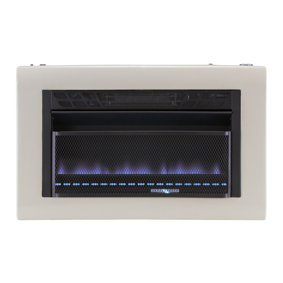
Cedar Ridge
h e a r t h
VENT-FREE GAS WALL
HEATER
OWNER'S OPERATION AND
INSTALLATION MANUAL
BLUE FLAME MODEL
MTF30TBU
PFS
WARNING: If the information in this manual is not
followed exactly, a fire or explosion may result causing
property damage, personal injury or loss of life.
— Do not store or use gasoline or other flammable va-
pors and liquids in the vicinity of this or any other
appliance.
— WHAT TO DO IF YOU SMELL GAS
• Do not try to light any appliance.
• Do not touch any electrical switch; do not use any
phone in your building.
• Immediately call your gas supplier from a neighbor's
phone. Follow the gas supplier's instructions.
• If you cannot reach your gas supplier, call the fire
department.
— Installation and service must be performed by a quali-
fied installer, service agency or the gas supplier.
WARNING: This appliance is equipped for Natural and
Propane gas. Field conversion is not permitted other than
between natural or propane gases.
Questions, problems, missing parts? Before returning to your retailer, call
our customer service department at 1-866-573-0674, 8:00 am - 4:30 pm CST,
Monday through Friday or email customerservice@usaprocom.com
®
®
US
Advertisement
Table of Contents

Related Manuals for Cedar Ridge MTF30TBU


Summary of Contents for Cedar Ridge MTF30TBU
- Page 1 Cedar Ridge ® h e a r t h VENT-FREE GAS WALL HEATER OWNER’S OPERATION AND INSTALLATION MANUAL BLUE FLAME MODEL MTF30TBU ® WARNING: If the information in this manual is not followed exactly, a fire or explosion may result causing property damage, personal injury or loss of life.
-
Page 2: Table Of Contents
TABLE OF CONTENTS Safety ............3 Operation ..........18 Specifications ..........4 Electrical Connection ....... 21 Important Electrical Safety Information..5 Electrical Wiring Diagram ......22 Qualified Installing Agency ......6 Inspecting Burners........23 Product Features ........6 Care And Maintenance ......24 Local Codes.......... -
Page 3: Safety
SAFETY NATURAL AND PROPANE/LP GAS: Natural IMPORTANT: Read this owner’s and Propane/LP gas are odorless. An odor- manual carefully and completely making agent is added to the gas. The odor before trying to assemble, op- helps you detect a gas leak. However, the erate, or service this heater. -
Page 4: Specifications
100 lbs. capacity. 6. Do not run heater: • Where flammable liquids or vapors are used or stored. • Under dusty conditions. SPECIFICATIONS Model MTF30TBU Gas Type Natural Gas Propane Gas Ignition Electric Piezo Ignitor Electric Piezo Ignitor BTU/Hr (available) -
Page 5: Important Electrical Safety Information
IMPORTANT ELECTRICAL SAFETY INFORMATION When using electrical appliances, basic pre- 9. To disconnect heater, turn controls to OFF, cautions should always be followed to reduce then remove plug from outlet. the risk of fire, electric shock, and injury to 10. Connect to properly grounded outlets only. persons, including the following: 11. -
Page 6: Qualified Installing Agency
QUALIFIED INSTALLING AGENCY Only a qualified agency should install and a) Installing, testing, or replacing gas piping replace gas piping, gas utilization equipment or accessories, and repair and equipment ser- b) Connecting, installing, testing, repairing, vicing. The term “qualified agency” means any or servicing equipment;... -
Page 7: Preparing For Installation
PREPARING FOR INSTALLATION Blower Switch Before beginning assembly or operation of the product, make sure all parts are present. Heater Coil Switch Compare parts with package contents list and Figure 1. If any part is missing or damaged, Ignitor do not attempt to assemble, install or operate Button Control the product. -
Page 8: Air For Combustion And Ventilation
AIR FOR COMBUSTION AND VENTILATION heat loss in homes. Home owners weather WARNING: This heater shall strip and caulk around windows and doors not be installed in a confined space to keep the cold air out and the warm air in. During heating months, home owners want or unusually tight construction their homes as airtight as possible. - Page 9 AIR FOR COMBUSTION AND VENTILATION DETERMINING FRESH-AIR FLOW FOR HEATER LOCATION Determining if You Have a Confined 4. Compare the maximum Btu/Hr the space or Unconfined Space can support with the actual amount of Btu/ Use this work sheet to determine if you have Hr used.
- Page 10 AIR FOR COMBUSTION AND VENTILATION VENTILATION AIR Ventilation Air From Inside Building This fresh air would come from an adjoining 1 and 2, Figure 2). You can also remove door unconfined space. When ventilating to an into adjoining room (see option 3, Figure 2). adjoining unconfined space, you must provide Follow the National Fuel Gas Code, ANSI two permanent openings: one within 12"...
-
Page 11: Installation
INSTALLATION IMPORTANT: Vent-free heaters add moisture NOTICE: This heater is intended to the air. Although this is beneficial, installing for use as supplemental heat. heater in rooms without enough ventilation air Use this heater along with your may cause mildew to form too much moisture. primary heating system. - Page 12 INSTALLATION INSTALLING THERMOSTAT SENSING BULB (OPTIONAL) 1. Pull out the sensing bulb from the two clips located in the shipping position. There is no need to take out the two bulb clips. 2. Take out the bulb clip from the hardware package and insert it into the square hole.
- Page 13 INSTALLATION 3. Insert wall anchor (wings first) into hole. WARNING: Maintain mini- Tap anchor flush to wall. mum clearances shown in Figure 4. For thin walls (1/2" or less), insert red key into wall anchor. Push red key to “pop” 4, page 11.
- Page 14 INSTALLATION INSTALLING BASE FEET 1. Snap the left and right foot columns to- 5. Position the heater to the desired location. gether (see Figure 12). Secure the base feet to the floor by us- ing two Phillips head self tapping screws 2.
- Page 15 INSTALLATION Change of the selector setting to other than Figure 15). Install hex plug into LP inlet the fuel type specified at the time of installa- of regulator. Install gas line into NG inlet tion could damage this appliance and render of regulator.
- Page 16 INSTALLATION CAUTION: Use only new, CAUTION: Avoid damage to black iron or steel pipe. Inter- regulator. Hold gas regulator nally tinned copper tubing may with wrench when connecting be used in certain areas. Check into gas piping and/or fittings. your local codes. Use pipe of 1/2"...
- Page 17 INSTALLATION IMPORTANT: Install an equipment shutoff external regulator with the vent pointing down valve in an accessible location. The equip- as shown in Figure 18, page 16. Pointing ment shutoff valve is for turning on or shutting the vent down protects it from freezing rain off the gas to the appliance.
-
Page 18: Operation
INSTALLATION PRESSURE TESTING HEATER GAS CONNECTIONS 1. Open equipment shutoff valve (see Figure fluid to all joints. Bubbles forming show a 19, page 17). leak. 2. Open gas supply tank valve. 5. Correct all leaks at once. 3. Make sure control knob of heater is in the 6. - Page 19 OPERATION LIGHTING INSTRUCTIONS 1. STOP! Read the safety information, 7. Keep control knob pressed in for 30 sec- page 18. onds after lighting pilot. After 30 seconds, release control knob. If control knob does 2. Make sure equipment shutoff valve is fully not pop up when released, contact a quali- open.
- Page 20 OPERATION TO TURN OFF GAS TO APPLIANCE Shutting Off Heater Shutting Off Burner Only (pilot stays lit ) Turn control knob clockwise to the OFF position. Turn control knob clockwise to the PILOT position. MANUAL LIGHTING PROCEDURE Ignitor 1. Remove front panel. Natural Electrode Thermocouple...
-
Page 21: Electrical Connection
ELECTRICAL CONNECTION GROUNDING INSTRUCTIONS A 15 amp, 120 Volt, 60 Hz circuit with a prop- erly grounded outlet is required. Preferably, This heater is for use on 120 volts. The cord the heater will be on a dedicated circuit as has a plug as shown at A in Figure 25. -
Page 22: Electrical Wiring Diagram
ELECTRICAL WIRING DIAGRAM Any electrical re-wiring of this appliance must CAUTION: Label all wires be done by a qualified electrician. This wiring prior to disconnection when must be done in accordance with local codes servicing controls. Wiring errors and/or in Canada with the current CSA C22.1 Canadian Electrical Code, and for US instal- can cause improper and danger- lations, the National Electrical Code ANSI/... -
Page 23: Inspecting Burners
INSPECTING BURNERS IMPORTANT: Owner’s should check pilot flame pattern and burner flame pattern often. Incorrect flame patterns indicate the need for cleaning (see Care and Maintenance, page 24) or service. WARNING: Only a qualified service person should service and repair heater. This includes maintenance requiring replacement or alteration of components. -
Page 24: Care And Maintenance
CARE AND MAINTENANCE WARNING: Turn off heater and let cool before servicing. CAUTION: You must keep control areas, burner, and circulating air passageways of heater clean. Inspect these areas of heater before each use. Have heater inspected yearly by a qualified service techni- cian. -
Page 25: Troubleshooting
CARE AND MAINTENANCE MAINTENANCE OF BLOWER MOTOR Always disconnect the appliance from the heavy or continuous use, periodic cleaning main power supply and allow it to cool must be done more frequently. If the heater before any servicing operation. blows alternating cold and warm air, check the fan for free movement and for debris restrict- The motors used on the fan heater and flame ing air flow. - Page 26 TROUBLESHOOTING Problem Possible Cause Corrective Action When ignitor button is 1. Gas supply is turned off or 1. Turn on gas supply or open pressed in there is a equipment shutoff valve is equipment shutoff valve. spark at ODS/pilot but closed.
- Page 27 TROUBLESHOOTING Problem Possible Cause Corrective Action High yellow flame during 1. Not enough air. 1. Check burner for dirt and debris. burner combustion If found, clean burner (see Care and Maintenance, page 24). 2. Gas regulator is defective. 2. Replace gas regulator. 3.
-
Page 28: Parts
PARTS MODEL MTF30TBU www.usaprocom.com 200006-01B... - Page 29 PARTS MODEL MTF30TBU This list contains replaceable parts for your heater. When ordering replacement parts, follow the instructions listed under Replacement Parts on page 30 of this manual. ITEM PART # DESCRIPTION UBD30T-130B Screen Assembly UBD30T-120B Front Panel Assembly UBD30T-160B...
-
Page 30: Replacement Parts
REPLACEMENT PARTS Note: Use only original replacement parts. This will protect your warranty coverage for parts replaced under warranty. PARTS UNDER WARRANTY Contact authorized dealers of this product. • Model and serial number of your heater If they can’t supply original replacement •... -
Page 31: Service Hints
SERVICE HINTS When Gas Pressure Is Too Low • pilot will not stay lit • burners will have delayed ignition • fireplace will not produce specified heat • propane/LP gas supply might be low (propane/LP units only) You may feel your gas pressure is too low. If so, contact your local gas supplier. TECHNICAL SERVICE You may have further questions about installation, operation, or troubleshooting. -
Page 32: Warranty
WARRANTY KEEP THIS WARRANTY Model _______________________________ Serial No. ____________________________ Date Purchased _______________________ Keep receipt for warranty verification. REGISTER YOUR PRODUCT AT WWW.USAPROCOM.COM IMPORTANT: We urge you to register your product within 10 days of date of installation, complete with entire serial number which can be found on the rating plate. Please fill out the warranty infor- mation above for your personal records.
Need help?
Do you have a question about the MTF30TBU and is the answer not in the manual?
Questions and answers