Table of Contents
Advertisement
Quick Links
Service
Manual
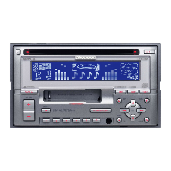
MULTI-CD CONTROL DSP HIGH POWER CD CASSETTE PLAYER WITH FM/AM TUNER
FH-P4000
MULTI-CD CONTROL DSP HIGH POWER CD CASSETTE PLAYER WITH RDS TUNER
FH-P4000R
- This service manual should be used together with the following manual(s):
Model No.
Order No.
CX-977
CRT2624
CX-1011
CRT2406
- Dolby noise reduction manufactured under license from Dolby Laboratories Licensing Corporation.
"Dolby" and the double-D symbol are trademarks of Dolby Laboratories Licensing Corporation.
CONTENTS
1. SAFETY INFORMATION ............................................3
2. EXPLODED VIEWS AND PARTS LIST .......................4
4. PCB CONNECTION DIAGRAM ................................40
5. ELECTRICAL PARTS LIST ........................................50
6. ADJUSTMENT..........................................................67
PIONEER CORPORATION
PIONEER ELECTRONICS SERVICE INC.
Haven 1087 Keetberglaan 1, 9120 Melsele, Belgium
PIONEER EUROPE NV
PIONEER ELECTRONICS ASIACENTRE PTE.LTD. 253 Alexandra Road, #04-01, Singapore 159936
C PIONEER CORPORATION 2001
FH-P4000/X1N/UC
Mech. Module Remarks
S9
CD Mech. Module:Circuit Description, Mech.Description, Disassembly
3L
Cassette Mech. Module:Mech.Description, Disassembly, Adjustment
4-1, Meguro 1-Chome, Meguro-ku, Tokyo 153-8654, Japan
P.O.Box 1760, Long Beach, CA 90801-1760 U.S.A.
ENT
ENT
DISP
DISP
CLOCK
CLOCK
D
F
LOUD
LOUD
SOURCE / OFF
SOURCE
OFF
A
1
2
3
4
5
6
X1N/EW
7. GENERAL INFORMATION .......................................72
7.1 DIAGNOSIS ........................................................72
7.1.1 TEST MODE ..............................................72
7.1.2 DISASSEMBLY .........................................76
7.1.3
7.2 PARTS .................................................................81
7.2.1 IC................................................................81
7.2.2 DISPLAY ....................................................96
7.3 OPERATIONAL FLOW CHART ...........................97
8. OPERATIONS AND SPECIFICATIONS.....................98
ORDER NO.
CRT2674
X1N/UC,X1N/ES
.......80
K-ZZA. MAR. 2001 Printed in Japan
Advertisement
Table of Contents

Related Manuals for Pioneer FH-P4000R X1N


Summary of Contents for Pioneer FH-P4000R X1N
-
Page 1: Table Of Contents
PIONEER ELECTRONICS SERVICE INC. P.O.Box 1760, Long Beach, CA 90801-1760 U.S.A. Haven 1087 Keetberglaan 1, 9120 Melsele, Belgium PIONEER EUROPE NV PIONEER ELECTRONICS ASIACENTRE PTE.LTD. 253 Alexandra Road, #04-01, Singapore 159936 C PIONEER CORPORATION 2001 K-ZZA. MAR. 2001 Printed in Japan... - Page 2 FH-P4000,P4000R - CD Player Service Precautions 2. During disassembly, be sure to turn the power off 1. For pickup unit(CXX1480) handling, please refer since an internal IC might be destroyed when a con- to"Disassembly"(see page 76). nector is plugged or unplugged. During replacement, handling precautions shall be 3.
-
Page 3: Safety Information
FH-P4000,P4000R 1. SAFETY INFORMATION CAUTION This service manual is intended for qualified service technicians; it is not meant for the casual do-it-yourselfer. Qualified technicians have the necessary test equipment and tools, and have been trained to properly and safely repair complex products such as those covered by this manual. -
Page 4: Exploded Views And Parts List
FH-P4000,P4000R 2. EXPLODED VIEWS AND PARTS LIST 2.1 PACKING NOTE: - Parts marked by “*” are generally unavailable because they are not in our Master Spare Parts List. - Screws adjacent to ∇ mark on the product are used for disassembly. (1) PACKING SECTION PARTS LIST Mark No. - Page 5 FH-P4000,P4000R (2) CONTRAST TABLE FH-P4000/X1N/UC, FH-P4000R/X1N/EW and FH-P4000/X1N/ES are constructed the same except for the following: Part No. Mark No. Symbol and Description FH-P4000/X1N/UC FH-P4000R/X1N/EW FH-P4000/X1N/ES 1 Cord Assy CDE6438 CDE6435 CDE6603 2 Screw Assy CEA2789 CEA2788 CEA2788 4 Screw(M2x4) CBA1488 Not used Not used...
- Page 6 FH-P4000,P4000R There is a possibility of damaging screws if the torque for tightning the screw indicat- ed by arrows more than 0.6N. Keep the designated torque. 2.2 EXTERIOR(FH-P4000/X1N/UC)
- Page 7 FH-P4000,P4000R - EXTERIOR SECTION PARTS LIST Mark No. Description Part No. Mark No. Description Part No. 1 Screw BSZ26P060FMC 46 Spring CBH2182 2 Screw BSZ26P080FZK 47 Cover CNM6276 48 ••••• 3 Screw BSZ26P160FMC 4 Cord Assy CDE6438 49 Screw IMS20P040FZK 5 Cable CDE6497 50 Detach Grille Assy...
- Page 8 FH-P4000,P4000R There is a possibility of damaging screws if the torque for tightning the screw indicat- ed by arrows more than 0.6N. Keep the designated torque. 2.3 EXTERIOR(FH-P4000R/X1N/EW)
- Page 9 FH-P4000,P4000R - EXTERIOR SECTION PARTS LIST Mark No. Description Part No. Mark No. Description Part No. 1 Screw BSZ26P060FMC 46 Spring CBH2182 2 Screw BSZ26P080FZK 47 Cover CNM6276 48 ••••• 3 Screw BSZ26P160FMC 4 ••••• 49 Screw IMS20P040FZK 5 Cable CDE6497 50 Detach Grille Assy CXB6686...
- Page 10 FH-P4000,P4000R There is a possibility of damaging screws if the torque for tightning the screw indicat- ed by arrows more than 0.6N. Keep the designated torque. 2.4 EXTERIOR(FH-P4000/X1N/ES)
- Page 11 FH-P4000,P4000R - EXTERIOR SECTION PARTS LIST Mark No. Description Part No. Mark No. Description Part No. 1 Screw BSZ26P060FMC 46 Keyboard Unit CWM7530 2 Screw BSZ26P080FZK 47 LCD(LCD1000) CAW1664 48 Connector(CN1000) CKS3580 3 Screw BSZ26P160FMC 4 Cord Assy CDE6603 49 Holder CNC9168 5 Cable CDE6497...
- Page 12 FH-P4000,P4000R 2.5 CD MECHANISM MODULE...
- Page 13 FH-P4000,P4000R - CD MECHANISM MODULE SECTION PARTS LIST Mark No. Description Part No. Mark No. Description Part No. 1 Control Unit CWX2481 46 Gear CNV6320 2 Connector(CN701) CKS1959 47 Arm CNV6322 3 Connector(CN101) CKS3486 48 Arm CNV6323 4 Screw BMZ20P025FMC 49 Arm CNV6324 5 Screw...
- Page 14 FH-P4000,P4000R 2.6 CASSETTE MECHANISM MODULE...
- Page 15 FH-P4000,P4000R - CASSETTE MECHANISM MODULE SECTION PARTS LIST Mark No. Description Part No. Mark No. Description Part No. 1 Screw BSZ20P040FMC 46 Pinch Roller ENV1518 2 Washer CBF1037 47 Pinch Holder Unit EXA1607 3 Washer CBG1003 48 Pinch Roller ENV1518 4 Screw EBA1028 49 Reel Unit...
-
Page 16: Block Diagram And Schematic Diagram
FH-P4000,P4000R 3. BLOCK DIAGRAM AND SCHEMATIC DIAGRAM 3.1 BLOCK DIAGRAM AUDIO AMP UNIT CN451 FM/AM TUNER UNIT ANTENNA FM/AM 1ST IF 10.7MHz MPXREF 41kHz AMRF T51 Q51 CF51 CF52 CF53 AMDET AMANT L ch IC 2 FM MPX R ch ANT ADJ COMP MIXER, IF AMP, DET. - Page 17 FH-P4000,P4000R SYSTEM MICRO COMPUTER X601 IC 601 (1/2) PE5211A SW. VDD Q801 SWVDD CN851 SWVDD Q802 TUNPCE1 A SENSE, B SENSE VDSENS TUNPCK CDVD Q821 TUNPCE2 BSENS TUNPDI TUNPDO ASENS CS, IFCK, IFDI, IFDO, ACK, ERR, IFOK, DOUT SDA, SCL, SEL CDL+ POWER AMP CASSL...
- Page 18 FH-P4000,P4000R 3.2 OVERALL CONNECTION DIAGRAM(GUIDE PAGE) (FH-P4000/X1N/UC, FH-P4000/X1N/ES) Note: When ordering service parts, be sure to refer to “EXPLODED VIEWS AND PARTS LIST” or “ELECTRICAL PARTS LIST”. CONTROL UNIT CN701 CD:+4.22dBs Large size IP-BUS:+2.2dBs SCH diagram Guide page Detailed page FM(100%): -19.5dBs AM(30%): -30.0dBs IP-BUS: +2.2dBs...
- Page 19 FH-P4000,P4000R FM(100%):-12.5dBs AM(30%):-23.0dBs AUDIO AMP UNIT IP-BUS: -0.8dBs TAPE:-16.0dBs CD:-0.78dBs FRONT OUTPUT FM(100%): -8.5dBs REAR AM(30%): -19.0dBs OUTPUT IP-BUS: +3.2dBs TAPE: -12.0dBs CD:+3.22dBs > FM(100%):+3.72dBs FM(100%): -8.9dBs (1A) AM(30%): -6.78dBs AM(30%): -19.4dBs IP-BUS:+9.42dBs IP-BUS: +2.8dBs TAPE: -4.98dBs TAPE: -11.6dBs CD:+9.44dBs CD:+2.82dBs >...
- Page 20 FH-P4000,P4000R...
- Page 21 FH-P4000,P4000R...
- Page 22 FH-P4000,P4000R...
- Page 23 FH-P4000,P4000R...
- Page 24 FH-P4000,P4000R 3.3 OVERALL CONNECTION DIAGRAM(GUIDE PAGE) (FH-P4000R/X1N/EW) Note: When ordering service parts, be sure to refer to “EXPLODED VIEWS AND PARTS LIST” or “ELECTRICAL PARTS LIST”. CONTROL UNIT CN701 CD:+4.22dBs IP-BUS:+2.2dBs FM(100%): -15.5dBs AM(30%): -26.0dBs IP-BUS: +2.2dBs TAPE: -9.0dBs CD:+4.22dBs TAPE:-9dBs FM(100%): +8.48dBs AM(30%): -2.02dBs...
- Page 25 FH-P4000,P4000R FM(100%): -8.5dBs AM(30%):-19.0dBs AUDIO AMP UNIT IP-BUS: -0.8dBs TAPE:-16.0dBs CD:-0.78dBs FRONT OUTPUT FM(100%): -4.5dBs REAR AM(30%): -15.0dBs OUTPUT IP-BUS: +3.2dBs TAPE: -12.0dBs CD:+3.22dBs > FM(100%):+7.72dBs FM(100%): -4.9dBs (1A) AM(30%): -2.78dBs AM(30%): -15.4dBs IP-BUS:+9.42dBs IP-BUS: +2.8dBs TAPE: -4.98dBs TAPE: -11.6dBs CD:+9.44dBs CD:+2.82dBs FM(100%):+34.48dBs...
- Page 26 FH-P4000,P4000R...
- Page 27 FH-P4000,P4000R...
- Page 28 FH-P4000,P4000R...
- Page 29 FH-P4000,P4000R...
- Page 30 FH-P4000,P4000R 3.4 KEYBOARD UNIT(FH-P4000/X1N/UC, FH-P4000/X1N/ES) PE5234B DISPLAY MICRO COMPUTER...
- Page 31 FH-P4000,P4000R KEYBOARD UNIT CN801...
- Page 32 FH-P4000,P4000R 3.5 KEYBOARD UNIT(FH-P4000R/X1N/EW) PE5234B...
- Page 33 FH-P4000,P4000R KEYBOARD UNIT CN801...
- Page 34 FH-P4000,P4000R 3.6 CD MECHANISM MODULE CONTROL UNIT PICKUP UNIT(SERVICE)(P9) RF AMP CN101 ACT/MOTOR DRIVER SPINDLE M1 CXB6007 LOADING/CARRIAGE M2 CXB5903 5V REGULATOR...
- Page 35 FH-P4000,P4000R SERVO CONTROL/DSP/DAC/LPF 16.934MHz SWITCHES: CONTROL UNIT S901 : HOME SWITCH..ON-OFF S902 : CLAMP SWITCH..ON-OFF S903 : DSCSNS SWITCH..ON-OFF S904 : 12EJ SWITCH..ON-OFF S905 : 8EJ SWITCH..ON-OFF The underlined indicates the switch position. CN701 CN181...
- Page 36 FH-P4000,P4000R Note:1. The encircled numbers denote measuring pointes in the circuit diagram. 2. Reference voltage VREF:2.1V - Waveforms 5 CH1:FD 1 CH1:DSCSNS 5V/div. 1 CH1:DSCSNS 5V/div. 500mV/div. 6 CH2:FOK 2 CH2:CLCONT 2 CH2:CLCONT 5V/div. 5V/div. 5V/div. 500ms/div. 500ms/div. 500ms/div. 7 CH3:MD 3 CH3:LOEJ 3 CH3:LOEJ 5V/div.
- Page 37 FH-P4000,P4000R % CH1:RFO 5 CH1:FD % CH1:RFO 1V/div. 1V/div. 1V/div. 200ms/div. 0 CH2:TE ^ CH2:FOP 0 CH2:TE 500µs/div. 1V/div. 5ms/div. 2V/div. 500mV/div. ! CH3:TD ! CH3:TD 1V/div. 1V/div. With no disk inserted 32 Track Jump During "Focus Close" 1 Track Jump Ref.
- Page 38 FH-P4000,P4000R 3.7 CASSETTE MECHANISM MODULE DECK UNIT CN252 C256 Rev-L Rev-R MUTE NF1(R) 120/70 Vref1 IC251 ser/REP RIN(L) Fwd-R HA12228F RIN(R) MSOUT C405 R033 Fwd-L R404 270K MSDET FIN(R) C404 Vref2 Dolby-B R403 MAOUT FIN(L) MSGV(R) NFI(L) HEAD ASSY EXA1589 TEST TAPE NCT-150 C255...
- Page 39 FH-P4000,P4000R M1 MOTOR UNIT (MAIN MOTOR) EXA1490 CN255 CN256 REEL SENSE CN253 EGN1 EGN1004 R375 R373 70µs ESG1007 MECHANISM MODE ESG1007 DRIVER load S1 LOAD ESG1007 REEL SENSE CN254 MOTOR UNIT (SUB MOTOR) VCC2 EXA1580 R374 C356 SWITCHES: REEL SENSE PCB C355 S1:LOAD SWITCH..EJECT-PLAY S2:MODE SWITCH....ON-OFF...
-
Page 40: Pcb Connection Diagram
FH-P4000,P4000R AUDIO AMP UNIT 4. PCB CONNECTION DIAGRAM CORD ASSY 4.1 AUDIO AMP UNIT NOTE FOR PCB DIAGRAMS 1. The parts mounted on this PCB include all necessary parts for several destination. For further information for respective destinations, be sure to check with the schematic dia- gram. - Page 41 FH-P4000,P4000R SIDE A FRONT OUTPUT IC,Q REAR OUTPUT IP-BUS INPUT ANTENNA JACK FRONT CN1000 CN251...
- Page 42 FH-P4000,P4000R IC,Q AUDIO AMP UNIT...
- Page 43 FH-P4000,P4000R SIDE B FRONT...
- Page 44 FH-P4000,P4000R 4.2 KEYBOARD UNIT SIDE A...
- Page 45 FH-P4000,P4000R SIDE B...
- Page 46 FH-P4000,P4000R 4.3 CD MECHANISM MODULE SIDE A...
- Page 47 FH-P4000,P4000R SIDE B...
- Page 48 FH-P4000,P4000R 4.4 CASSETTE MECHANISM MODULE DECK UNIT CN131 SIDE A CN251 C271 DECK UNIT SIDE B HEAD ASSY IC,Q VR302 CN254 CN255 CN253 IC351 CN252 IC251 Q351 Q352 VR301 CN256...
- Page 49 FH-P4000,P4000R REEL SENSE PCB LOAD 70µs MODE CN256 CN253 EGN1 REEL SENSE...
-
Page 50: Electrical Parts List
FH-P4000,P4000R 5. ELECTRICAL PARTS LIST NOTES: - Parts whose parts numbers are omitted are subject to being not supplied. - The part numbers shown below indicate chip components. Chip Resistor RS1/_S___J,RS1/__S___J Chip Capacitor (except for CQS..) CKS.., CCS.., CSZS..=====Circuit Symbol and No.===Part Name Part No. - Page 51 FH-P4000,P4000R =====Circuit Symbol and No.===Part Name Part No. =====Circuit Symbol and No.===Part Name Part No. ------ ------------------------------------------ ------------------------- ------ ------------------------------------------ ------------------------- Ferri-Inductor LAU2R2K RS1/16S562J Choke Coil 600µH CTH1221 RS1/16S562J Thermistor CCX1037 RS1/16S562J Radiator 22.5792MHz CSS1532 RS1/16S562J Radiator 6.291456MHz CSS1505 RS1/16S0R0J Switch(DETACH) CSG1059 RS1/16S0R0J...
- Page 52 FH-P4000,P4000R =====Circuit Symbol and No.===Part Name Part No. =====Circuit Symbol and No.===Part Name Part No. ------ ------------------------------------------ ------------------------- ------ ------------------------------------------ ------------------------- RS1/16S473J RS1/16S0R0J RS1/16S472J RS1/16S103J RS1/16S473J RS1/16S102J RS1/16S222J RS1/16S223J RS1/16S222J RS1/16S223J RS1/16S182J RS1/16S0R0J RS1/16S182J RS1/16S102J RS1/16S473J RS1/16S0R0J RS1/16S0R0J RS1/16S102J RS1/16S0R0J RS1/16S102J RS1/16S473J RS1/16S473J...
- Page 53 FH-P4000,P4000R =====Circuit Symbol and No.===Part Name Part No. =====Circuit Symbol and No.===Part Name Part No. ------ ------------------------------------------ ------------------------- ------ ------------------------------------------ ------------------------- CKSRYB105K10 CKSRYB104K16 CEJA220M16 CKSRYB473K16 CKSRYB104K16 CKSRYB104K16 CEJA100M16 CEAL3R3M50 CKSRYB105K6R3 CEAL3R3M50 CKSRYB105K6R3 CEAL3R3M50 CEJA470M10 CEAL3R3M50 CKSRYB105K6R3 CKSRYB102K50 CKSRYB104K16 CKSRYB102K50 CEALNP4R7M16 CKSRYB102K50 CEALNP4R7M16 CKSRYB102K50...
- Page 54 FH-P4000,P4000R =====Circuit Symbol and No.===Part Name Part No. =====Circuit Symbol and No.===Part Name Part No. ------ ------------------------------------------ ------------------------- ------ ------------------------------------------ ------------------------- CKSRYB103K50 Transistor 2SD1767 CKSRYB103K50 Diode 1SS133 CEAL101M10 Diode MA3056(M) 2200µF/16V CCH1001 Diode MA152WK CKSRYB104K16 Diode MA111 CKSRYB104K16 Diode Network DA204U CKSRYB473K16 Diode Network...
- Page 55 FH-P4000,P4000R =====Circuit Symbol and No.===Part Name Part No. =====Circuit Symbol and No.===Part Name Part No. ------ ------------------------------------------ ------------------------- ------ ------------------------------------------ ------------------------- Inductor CTF1379 RS1/16S102J Inductor CTF1379 RS1/16S103J Inductor CTF1379 RS1/16S474J Inductor CTF1379 RS1/16S103J Inductor CTF1379 RS1/16S103J Inductor CTF1379 RS1/16S474J Inductor CTF1379 RS1/16S562J Inductor...
- Page 56 FH-P4000,P4000R =====Circuit Symbol and No.===Part Name Part No. =====Circuit Symbol and No.===Part Name Part No. ------ ------------------------------------------ ------------------------- ------ ------------------------------------------ ------------------------- RS1/16S473J RS1/16S0R0J RS1/16S103J RAB4C221J RS1/16S681J RS1/16S0R0J RS1/16S681J RS1/16S0R0J RS1/16S681J RS1/16S0R0J RS1/16S681J RS1/16S221J RS1/16S681J RS1/16S221J RS1/16S681J RS1/16S221J RS1/16S681J RS1/16S221J RS1/16S393J RAB4C473J RS1/16S102J RS1/16S473J...
- Page 57 FH-P4000,P4000R =====Circuit Symbol and No.===Part Name Part No. =====Circuit Symbol and No.===Part Name Part No. ------ ------------------------------------------ ------------------------- ------ ------------------------------------------ ------------------------- RS1/16S471J CKSRYB222K50 RS1/16S223J CKSRYB222K50 RS1/16S221J CKSRYB222K50 RS1/16S332J CKSRYB222K50 RS1/16S152J CEJA220M6R3 RS1/16S681J CEJA220M6R3 RS1/16S472J CEJA220M6R3 RS1/16S102J CKSRYB104K16 RS1/16S102J CKSRYB104K16 RS1/16S102J CEJA220M6R3 RS1/16S473J CEJA220M6R3...
- Page 58 FH-P4000,P4000R =====Circuit Symbol and No.===Part Name Part No. =====Circuit Symbol and No.===Part Name Part No. ------ ------------------------------------------ ------------------------- ------ ------------------------------------------ ------------------------- CCSRCH101J50 PE5211A CCSRCH470J50 S-80735ANDZI CCSRCH220J50 TPD1018F CKSRYB102K50 Transistor 2SA1037K CEJA220M10 Transistor DTC114EK CKSRYB104K16 Transistor DTC124EU CCSRCH471J50 Transistor 2SA1797 CEJA220M10 Transistor 2SD1767 CKSRYB104K16...
- Page 59 FH-P4000,P4000R =====Circuit Symbol and No.===Part Name Part No. =====Circuit Symbol and No.===Part Name Part No. ------ ------------------------------------------ ------------------------- ------ ------------------------------------------ ------------------------- Inductor CTF1379 RS1/16S473J Inductor CTF1379 RS1/16S473J Inductor CTF1379 RS1/16S473J Inductor CTF1379 RS1/16S104J Inductor CTF1379 RS1/16S223J Inductor CTF1379 RS1/16S152J Inductor CTF1379 RS1/16S472J Inductor...
- Page 60 FH-P4000,P4000R =====Circuit Symbol and No.===Part Name Part No. =====Circuit Symbol and No.===Part Name Part No. ------ ------------------------------------------ ------------------------- ------ ------------------------------------------ ------------------------- RS1/16S223J RS1/16S0R0J RS1/16S103J RS1/16S0R0J RS1/16S473J RS1/16S473J RS1/16S103J RS1/16S0R0J RS1/16S103J RS1/16S0R0J RS1/16S102J RS1/16S473J RS1/16S473J RS1/16S473J RS1/16S331J RS1/16S0R0J RS1/16S223J RS1/16S221J RS1/16S473J RS1/16S221J RS1/16S103J RS1/16S221J...
- Page 61 FH-P4000,P4000R =====Circuit Symbol and No.===Part Name Part No. =====Circuit Symbol and No.===Part Name Part No. ------ ------------------------------------------ ------------------------- ------ ------------------------------------------ ------------------------- RS1/16S223J CCSRCH180J50 RS1/16S473J CKSRYB103K50 RS1/16S272J CEAL220M6R3 RS1/16S472J CEAL220M6R3 RS1/16S223J CKSRYB104K16 RS1/16S0R0J CKSRYB222K50 RS1/16S332J CKSRYB222K50 RS1/16S471J CKSRYB222K50 RS1/16S223J CKSRYB222K50 RS1/16S221J CEJA220M6R3 RS1/16S332J CEJA220M6R3...
- Page 62 FH-P4000,P4000R =====Circuit Symbol and No.===Part Name Part No. =====Circuit Symbol and No.===Part Name Part No. ------ ------------------------------------------ ------------------------- ------ ------------------------------------------ ------------------------- CKSRYB102K50 1000 Ceramic Resonator 4.72MHz CSS1430 CKSRYB222K50 1100 Push Switch CSG1129 CKSRYB103K50 1101 Push Switch CSG1111 CCSRCH270J50 1102 Push Switch CSG1129 CCSRCH270J50 1103...
- Page 63 FH-P4000,P4000R =====Circuit Symbol and No.===Part Name Part No. =====Circuit Symbol and No.===Part Name Part No. ------ ------------------------------------------ ------------------------- ------ ------------------------------------------ ------------------------- 1153 RS1/16S821J Unit Number : CWM7524(FH-P4000R/X1N/EW) 1154 RS1/16S122J Unit Name : Keyboard Unit 1155 RS1/16S182J 1156 RS1/16S302J MISCELLANEOUS 1157 RS1/16S101J IC 1000 PE5234B...
- Page 64 FH-P4000,P4000R =====Circuit Symbol and No.===Part Name Part No. =====Circuit Symbol and No.===Part Name Part No. ------ ------------------------------------------ ------------------------- ------ ------------------------------------------ ------------------------- 1006 RS1/16S474J 1186 RS1/16S181J 1007 RS1/16S102J 1187 RS1/16S181J 1009 RS1/16S102J 1188 RS1/16S181J 1010 RS1/16S224J 1011 RS1/16S102J CAPACITORS 1012 RS1/16S473J 1001 CKSRYB102K50 1013...
- Page 65 FH-P4000,P4000R =====Circuit Symbol and No.===Part Name Part No. =====Circuit Symbol and No.===Part Name Part No. ------ ------------------------------------------ ------------------------- ------ ------------------------------------------ ------------------------- 1100 Push Switch CSG1129 1153 RS1/16S821J 1101 Push Switch CSG1111 1154 RS1/16S122J 1102 Push Switch CSG1129 1155 RS1/16S182J 1103 Push Switch CSG1129 1156...
- Page 66 FH-P4000,P4000R =====Circuit Symbol and No.===Part Name Part No. =====Circuit Symbol and No.===Part Name Part No. ------ ------------------------------------------ ------------------------- ------ ------------------------------------------ ------------------------- Unit Number : CWX2481 RS1/16S102J RS1/16S102J Unit Name : Control Unit RS1/16S104J RS1/16S473J MISCELLANEOUS RS1/16S273J TA2153FN CAPACITORS TC9495F2 BA5996FM CEV470M6R3 BA05SFP CKSRYB102K50...
-
Page 67: Adjustment
FH-P4000,P4000R =====Circuit Symbol and No.===Part Name Part No. =====Circuit Symbol and No.===Part Name Part No. ------ ------------------------------------------ ------------------------- ------ ------------------------------------------ ------------------------- RESISTORS CKSRYB103K50 CKSQYB104K50 CKSRYB103K50 RS1/16S183J CKSRYB392K50 RS1/16S0R0J CKSRYB334K10 RS1/16S102J RS1/16S102J CKSRYB223K25 RS1/16S102J CKSRYB103K50 CKSRYB333K16 RS1/16S102J RS1/16S274J Unit Number : RS1/8S301J Unit Name : Reel Sense PCB... - Page 68 FH-P4000,P4000R 6.2 CD ADJUSTMENT 1) Precautions 2) Test Mode • This unit uses a single power supply (+5V) for the reg- This mode is used for adjusting the CD mechanism ulator. The signal reference potential, therefore, is module of the device. connected to VREF(approx.
- Page 69 FH-P4000,P4000R - Flow Chart [4]+[6]+Reset [KEY] Test Mode In Contents Display [CD] or [SOURCE] Source On [BAND] RF AMP Power On Power On New Test Mode Gain switching (T. offset is adjusted) (T. offset is not adjusted) [BAND] Tracking Servo Focus Close / Automatic adjustment value CRG+...
- Page 70 FH-P4000,P4000R 6.3 CHECKING THE GRATING AFTER CHANGING THE PICKUP UNIT • Note : The grating angle of the PU unit cannot be adjusted after the PU unit is changed. The PU unit in the CD mecha- nism module is adjusted on the production line to match the CD mechanism module and is thus the best adjusted PU unit for the CD mechanism module.
- Page 71 FH-P4000,P4000R Ech → Xch 20mV/div, AC Grating waveform Fch → Ych 20mV/div, AC 0° 30° 45° 60° 75° 90°...
-
Page 72: General Information
FH-P4000,P4000R 7. GENERAL INFORMATION 7.1 DIAGNOSIS 7.1.1 TEST MODE - Error Messages If a CD is not operative or stopped during operation due to an error, the error mode is turned on and cause(s) of the error is indicated with a corresponding number. This arrangement is intended at reducing nonsense calls from the users and also for facilitating trouble analysis and repair work in servicing. - Page 73 FH-P4000,P4000R - New Test Mode S-CD plays the same way as before. If an error such as off focus, spindle unlocking, unreadable sub-code, or sound skipping occurs after setup, its cause and time occurred (in absolute time) are displayed. During setup, operational status of the control software is displayed. These displays and functions are prepared for enhancing aging in the servicing and efficiency of trouble analysis.
- Page 74 FH-P4000,P4000R (4) Display of Operational Status during Setup Status No. Contents Protective action Focus search start Focus search timeout. Focus search 2 Focus search timeout. Focus search 3 Focus search timeout. Focus search 4 Focus search timeout. Focus search(Setup protection) Focus slips off.
- Page 75 FH-P4000,P4000R (5) Display Examples 1) During Setup 8-digit display, 6-digit display 4-digit display(Auto setting) 4-digit display(Manual setting) TNO. Min Sec TNO. Min Sec 11 11' 11" 11' 11" 2) During Operation (TOC read, TRK search, Play, FF and REV) The same as in the normal mode. 3) When a Protection Error Occurred (A) Error display ((A)←→(B), (C) : BAND key) 8-digit display...
-
Page 76: Disassembly
FH-P4000,P4000R 7.1.2 DISASSEMBLY Removing the Case (not shown) 1. Remove the Case. CD Mechanism Module Removing the Panel Assy (Fig.1) Remove the three screws and then remove the Panel Assy. Removing the CD Mechanism Module (Fig.1) Remove the four screws. Disconnect the connector and then remove the CD Mechanism Module. - Page 77 FH-P4000,P4000R Removing the Cassette Mechanism Module (Fig.3) Remove the four screws and then remove the Cassette Mechanism Module. Cassette Mechanism Module Fig.3 Removing the Audio Amp Unit (Fig.4) Remove the two screws. Remove the screw. Straight the tabs at five locations indicated. Remove the screw and then remove the Audio Amp Unit.
- Page 78 FH-P4000,P4000R - How to hold the Mechanical Unit 1. Hold the top and bottom frame. 2. Do not squeeze top frame's front portion too tight, because it is fragile. Do not squeeze. - How to remove the Top and Bottom Frame 1.
- Page 79 FH-P4000,P4000R - How to remove the Control Unit 1. Give jumper-solder treatment to the Flexible Wire of Jumper-Solder the Pickup unit, then remove the wire from the Connector. Control Unit 2. Remove all 4 points of solder-treatment on the Lead Wire.
-
Page 80: Connector Function Description
FH-P4000,P4000R 7.1.3 CONNECTOR FUNCTION DESCRIPTION 1. BUS+ 2. GND 3. GND 4. NC 5. BUS- 6. GND 7. BUS L+ INPUT 8. ASENB 9. BUS R+ INPUT 10. BUS R- INPUT 11. BUS L- INPUT REAR OUTPUT 1. RR+ ANTENNA JACK 2. -
Page 81: Parts
FH-P4000,P4000R 7.2 PARTS 7.2.1 IC PML011A PE5234B PDH033A PD2064A TA2153FN PE5211A TC9495F2 PE5210A BA5996FM SED1526F0A HA12228F PML011A MUTE SIGGN D Reference-voltage- Level-selector generator CassL Output-selector bypass line CODEC- IF (4ch independent control) DC: 4.15 % 1.65 AC: 2Vr ms%0.8Vr ms CassR Bypass -gain... - Page 82 FH-P4000,P4000R - Pin Functions (PD2064A) Pin No. Pin Name Function and Operation ECKO Amplifier output for external clock input ECKI Amplifier input for external clock input GNDX GND for oscillation circuit GNDAL GND(DAC L channel) DAC analog signal output(L channel) DAC L channel reference voltage VDAL Power supply(DAC L channel)
- Page 83 FH-P4000,P4000R Pin No. Pin Name Function and Operation IFDO Micon interface Data output(I C bus : open) IFOK Micon interface Operation flag output Micon interface Acknowledge output Micon interface Error flag output I2CS Micon interface I C bus switching BOOT Self boot control Boot address setting 0 Boot address setting 1...
- Page 84 FH-P4000,P4000R - Pin Functions (PE5211A) Pin No. Pin Name Function and Operation TUN:stereo input TUN:SD input Not used LOCH TUN:Local H output LOCL TUN:Local L output Not used RESET System reset input Crystal oscillator connection pin Crystal oscillator connection pin PLL:Regulator grand potential REGC1 PLL:Capacitor for regulator connect pin...
- Page 85 FH-P4000,P4000R Pin No. Pin Name Function and Operation 3L:Capstan motor control input STBY 3L:Drive IC control output Not used ILMPW Illumination power supply control output AUTOANT Auto antenna power output MUTE Mute output SYSPW System power supply control output DALMON For consumption low-current output EMUTE DOLPHIN Mute input...
- Page 86 FH-P4000,P4000R - Pin Functions (PE5210A) Pin No. Pin Name Function and Operation TUN:stereo input TUN:SD input RECIVE RDS:During RDS data reception LOCH TUN:Local H output LOCL TUN:Local L output Not used AM/FM RDS:RDS decoder power supply control output TMUTE TUN:Tuner mute output RESET System reset input Crystal oscillator connection pin...
- Page 87 FH-P4000,P4000R Pin No. Pin Name Function and Operation LOADSW 3L:Loading SW input 3L:Position sense output 3L:Reverse sense input 3L:Normal sense input 3L:Sub motor control input 2 3L:Sub motor control input 1 3L:Capstan motor control input STBY 3L:Drive IC control output Not used ILMPW Illumination power supply control output...
- Page 88 FH-P4000,P4000R - Pin Functions (SED1526F0A) Pin No. Pin Name Function and Operation V1-V5 Multilevel power supply for driving LCD Voltage adjustment +5V power supply VOUT Ascending voltage output CAP2- Ascending voltage capacitor connection CAP2+ Not used CAP1- Ascending voltage capacitor connection CAP2+ Ascending voltage capacitor connection IC master/slave operation select...
- Page 89 FH-P4000,P4000R - Pin Functions (PE5234B) Pin No. Pin Name Function and Operation Not used AVSS A/D converter ground potential Not used Aref1 A/D converter standard voltage DPDT Display data input KYDT Key data output Not used DADT D/A converter data output DACLK D/A converter clock output DAST...
- Page 90 FH-P4000,P4000R - Pin Functions(TA2153FN) Pin No. Pin Name Function and Operation Power supply voltage terminal RFGC RF amplitude adjustment control signal terminal GMAD AGC amplifier frequency characteristic adjustment terminal Main beam amplifier input terminal Main beam amplifier input terminal Sub beam amplifier input terminal Sub beam amplifier input terminal Monitor photodiode amplifier input terminal Laser diode amplifier output terminal...
- Page 91 FH-P4000,P4000R - Pin Functions(TC9495F2) Pin No. Pin Name Function and Operation TESTO Test mode terminal Replay speed flag output terminal uhso Replay speed flag output terminal EMPH Emphasis flag output terminal for sub code Q data LRCK Channel clock (44.1 kHz) output terminal Digital ground terminal Bit clock output terminal AOUT...
- Page 92 FH-P4000,P4000R Pin No. Pin Name Function and Operation 58-61 FLGA-D External flag output terminal for internal signal monitor Digital + power supply terminal (5 V) Digital ground terminal RF amplifier gain switching terminal Not used HOME detection switch input terminal FocusDrv and signal output terminal dmout Field equalizer PWM output terminal for IO0 and IO1...
- Page 93 FH-P4000,P4000R - Pin Functions(BA5996FM) Pin No. Pin Name Function and Operation Input pin for reference voltage OPIN2(+) Input pin for non-inverting input for CH2 preamplifier OPIN2(-) Input pin for inverting input for CH2 preamplifier OPOUT2 Output pin for CH2 preamplifier OPIN1(+) Input pin for non-inverting input for CH1 preamplifier OPIN1(-)
- Page 94 FH-P4000,P4000R HA12228F NFI(R) MUTE ON/off Dolby B-NR 120/70 Vref1 MUTE ON/off ser/REP RIN(L) for/REV RIN(R) MSOUT MSDET FIN(R) Vref2 MUTE ON/off MAOUT FIN(L) Dolby B-NR MSGv(R) NFI(L) *PDH033A :Not used :Power supply :Chip select input :Clock input :Data input TEST :Data output :Ground :Test...
- Page 95 FH-P4000,P4000R - FM/AM Tuner Unit FM/AM 1ST IF 10.7MHz MPXREF 41kHz AMRF T51 Q51 CF51 CF52 CF53 AMDET AMANT L ch IC 2 FM MPX R ch ANT ADJ COMP MIXER, IF AMP, DET. LDET FMANT RFGND FMRF CF202 IC 3 X901 IMG ADJ AM 2ND IF...
-
Page 96: Display
FH-P4000,P4000R 7.2.2 DISPLAY - CAW1664... -
Page 97: Operational Flow Chart
FH-P4000,P4000R 7.3 OPERATIONAL FLOW CHART Power ON VDD=5V 62pin bsens 96pin BSENS=L asens 97pin ASENS=L dsens 99pin DSENS=L ASENBO←H 87pin Starts communication with Grille microcomputer. 300ms SWVDD←H 137pin 300ms In case of the above signal, the communication Source keys with Grille microcomputer may fail. operative If the time interval is not 300msec, the oscillator may be defective. -
Page 98: Operations And Specifications
FH-P4000,P4000R 8. OPERATIONS AND SPECIFICATIONS... - Page 99 FH-P4000,P4000R...
- Page 100 FH-P4000,P4000R...
- Page 101 FH-P4000,P4000R...
- Page 102 FH-P4000,P4000R...
- Page 103 FH-P4000,P4000R...
- Page 104 FH-P4000,P4000R...
- Page 105 FH-P4000,P4000R...
- Page 106 FH-P4000,P4000R...