Table of Contents
Advertisement
GA-K8VM800M /
GA-K8VM800M-RH
AMD Socket 754 Processor Motherboard
User's Manual
Rev. 2004
12ME-K8VM800M-2004R
* The WEEE marking on the product indicates this product must not be disposed of with user's other household waste
and must be handed over to a designated collection point for the recycling of waste electrical and electronic equipment!!
* The WEEE marking applies only in European Union's member states.
Advertisement
Table of Contents

Related Manuals for Gigabyte GA-K8VM800M


Summary of Contents for Gigabyte GA-K8VM800M
- Page 1 GA-K8VM800M / GA-K8VM800M-RH AMD Socket 754 Processor Motherboard User's Manual Rev. 2004 12ME-K8VM800M-2004R * The WEEE marking on the product indicates this product must not be disposed of with user's other household waste and must be handed over to a designated collection point for the recycling of waste electrical and electronic equipment!!
- Page 4 Gigabyte's prior written permission. Specifications and features are subject to change without prior notice. Product Manual Classification In order to assist in the use of this product, Gigabyte has categorized the user manual in the following: For detailed product information and specifications, please carefully read the "Product User Manual".
-
Page 5: Table Of Contents
Table of Contents GA-K8VM800M(-RH) Motherboard Layout ... 7 Block Diagram ... 8 Chapter 1 Hardware Installation ... 9 Considerations Prior to Installation ... 9 Feature Summary ... 10 Installation of the CPU and Heatsink ... 12 1-3-1 Installation of the CPU ... 12 1-3-2 Installation of the Heatsink ... - Page 6 Chapter 3 Drivers Installation ... 45 Install Chipset Drivers ... 45 Software Application ... 46 Software Information ... 46 Hardware Information ... 47 Contact Us ... 47 Chapter 4 Appendix ... 49 Unique Software Utilities ... 49 4-1-1 EasyTune 5 Introduction ... 50 4-1-2 Xpress Recovery Introduction ...
-
Page 7: Ga-K8Vm800M(-Rh) Motherboard Layout
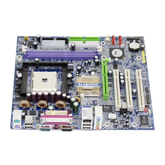
GA-K8VM800M(-RH) Motherboard Layout MS/KB R_USB ATX_12V AUDIO F_AUDIO IT8705 BIOS VIA 6103L CD_IN CODEC SPDIF_IO CPU_FAN Socket 754 VIA K8M800 PCI1 PCI2 PCI3 F_USB1 F_USB2 COMB - 7 - IDE2 IDE1 SYS_FAN SATA1 VIA VT8237R / VT8237R+ SATA0 F_PANEL PWR_LED... -
Page 8: Block Diagram
Block Diagram 4X/8X VGA Port AGPCLK (66MHz) RJ45 3 PCI VIA 6103L 2 Serial ATA PCICLK (33MHz) Althlon processor (K8) H.T. Bus 800MHz VIA K8M800 Mll-Link LPC BUS VIA VT8237R / VT8237R+ 8 USB Audio Ports CODEC ATA33/66/100/133 IDE Channels - 8 - CPUCLK+/- (200MHz) DDR RAM... -
Page 9: Chapter 1 Hardware Installation
2. Damage as a result of violating the conditions recommended in the user manual. 3. Damage due to improper installation. 4. Damage due to use of uncertified components. 5. Damage due to use exceeding the permitted parameters. 6. Product determined to be an unofficial Gigabyte product. - 9 - Hardware Installation... -
Page 10: Feature Summary
DDR400 memory modules. The DDR400 speed will drop down to DDR333 if you install two double-sided DDR400 memory modules. (Note 2) It is recommended to use SATA (1.5Gb/s) hard disks. GA-K8VM800M(-RH) Motherboard 64 processor (K8) /333/266/200 DIMM (Note 1) - Page 11 Supports @BIOS Supports EasyTune Overclocking Over Clock (CPU) by BIOS Over Voltage (CPU/AGP) by BIOS Form Factor Micro ATX form factor; 22.0cm x 24.4cm (Note 3) EasyTune functions may vary depending on different motherboards. (Note 3) - 11 - Hardware Installation...
-
Page 12: Installation Of The Cpu And Heatsink
CPU and gently press the metal lever back into its original position. Please use extra care when installing the CPU. The CPU will not fit if positioned incorrectly. Rather than applying force, please change the positioning of the CPU. GA-K8VM800M(-RH) Motherboard - 12 -... -
Page 13: Installation Of The Heatsink
1-3-2 Installation of the Heatsink Fig.1 Before installing the heat sink, please first add an even layer of heat sink paste on the surface of the CPU. Install all the heat sink components (Please refer to the heat sink manual for detailed installation instructions). Fig.2 Please connect the heat sink power connector to the CPU_FAN connector located on the motherboard so that the heat sink can properly function to... -
Page 14: Installation Of Memory
The motherboard supports DDR memory modules, whereby BIOS will automatically detect memory capacity and specifications. Memory modules are designed so that they can be inserted only in one direction. The memory capacity used can differ with each slot. GA-K8VM800M(-RH) Motherboard Notch Fig.1 The DIMM socket has a notch, so the DIMM memory module can only fit in one direction. -
Page 15: Installation Of Expansion Cards
Installation of Expansion Cards You can install your expansion card by following the steps outlined below: Read the related expansion card's instruction document before install the expansion card into the computer. Remove your computer's chassis cover, screws and slot bracket from the computer. Press the expansion card firmly into expansion slot in motherboard. -
Page 16: I/O Back Panel Introduction
Line Out (Front Speaker Out) Connect the stereo speakers, earphone or front surround channels to this connector. MIC In Microphone can be connected to MIC In jack. You can use audio software to configure 2-/4-/6- channel audio functioning. GA-K8VM800M(-RH) Motherboard - 16 -... -
Page 17: Connectors Introduction
Connectors Introduction 1) ATX_12V 2) ATX (Power Connector) 3) CPU_FAN 4) SYS_FAN 5) FDD 6) IDE1 / IDE2 7) SATA0 / SATA1 8) F_PANEL 9) PWR_LED 10) F_AUDO 11) CD_IN 12) SPDIF_IO 13) F_USB1 / F_USB2 14) IR 15) COMB 16) CLR_CMOS 17) BAT - 17 -... - Page 18 (300W or greater). If a power supply is used that does not provide the required power, the result can lead to an unstable system or a system that is unable to start. GA-K8VM800M(-RH) Motherboard Pin No. Definition...
- Page 19 3/4) CPU_FAN / SYS_FAN (Cooler Fan Power Connector) The cooler fan power connector supplies a +12V power voltage via a 3-pin power connector and possesses a foolproof connection design. Most coolers are designed with color-coded power connector wires. A red power connector wire indicates a positive connection and requires a +12V power voltage.
- Page 20 7) SATA0 / SATA1 (Serial ATA Connector) Serial ATA can provide up to150MB/s transfer rate. Please refer to the BIOS setting for the Serial ATA and install the proper driver in order to work properly. GA-K8VM800M(-RH) Motherboard IDE2 IDE1 Pin No.
-
Page 21: F_Panel (Front Panel Jumper)
F_PANEL (Front Panel Jumper) Please connect the power LED, PC speaker, reset switch and power switch etc of your chassis front panel to the F_PANEL connector according to the pin assignment below. HD (IDE Hard Disk Active LED) SPEAK (Speaker Connector) RES (Reset Switch) PW (Power Switch) MSG(Message LED/Power/Sleep LED) - Page 22 To find out if the chassis you are buying support front audio connector, please contact your dealer. Please note, you can have the alternative of using front audio connector or of using rear audio connector to play sound. GA-K8VM800M(-RH) Motherboard Pin No. Definition...
- Page 23 11) CD_IN (CD In Connector) Connect CD-ROM or DVD-ROM audio out to the connector. 12) SPDIF_IO (SPDIF In/ Out) The SPDIF output is capable of providing digital audio to external speakers or compressed AC3 data to an external Dolby Digital Decoder. Use this feature only when your stereo system has digital input function.
- Page 24 For optional front USB cable, please contact your local dealer. 14) IR Be careful with the polarity of the IR connector while you connect the IR. Please contact your nearest dealer for optional IR device. GA-K8VM800M(-RH) Motherboard Pin No. Definition Power...
- Page 25 15) COMB (COMB Connector) Be careful with the polarity of the COMB connector. Check the pin assignments while you connect the COMB cable. Please contact your nearest dealer for optional COMB cable. 16) CLR_CMOS (Clear CMOS) You may clear the CMOS data to its default values by this jumper. To clear CMOS, temporarily short 1-2 pin.
- Page 26 17) BAT (Battery) GA-K8VM800M(-RH) Motherboard Danger of explosion if battery is incorrectly replaced. Replace only with the same or equivalent type recommended by the manufacturer. Dispose of used batteries according to the manufacturer's instructions. If you want to erase CMOS...
-
Page 27: Chapter 2 Bios Setup
BIOS needs to be reset to its original settings. If you wish to upgrade to a new BIOS, either GIGABYTE's Q-Flash or @BIOS utility can be used. Q-Flash allows the user to quickly and easily update or backup BIOS without entering the operating system. -
Page 28: The Main Menu (For Example: Bios Ver. : D1)
This setup page is control CPU’s clock and frequency ratio. Load Fail-Safe Defaults Fail-Safe Defaults indicates the value of the system parameters which the system would be in safe configuration. GA-K8VM800M(-RH) Motherboard Load Fail-Safe Defaults Load Optimized Defaults Set Supervisor Password Set User Password Save &... - Page 29 Load Optimized Defaults Optimized Defaults indicates the value of the system parameters which the system would be in best performance configuration. Set Supervisor Password Change, set, or disable password. It allows you to limit access to the system and Setup, or just to Setup. Set User Password Change, set, or disable password.
-
Page 30: Standard Cmos Features
Select this if no SATA IDE devices are used and the system will skip the automatic detection step and allow for faster system start up. Access Mode Use this to set the access mode for the hard drive. The two options are: Large/Auto(default:Auto) GA-K8VM800M(-RH) Motherboard Standard CMOS Features Wed, May 11 2005 10:40:9... - Page 31 Capacity Capacity of currently installed hard disk. Hard drive information should be labeled on the outside drive casing. Enter the appropriate option based on this information. Cylinder Number of cylinders Head Number of heads Precomp Write precomp Landing Zone Landing zone Sector Number of sectors Drive A / Drive B...
-
Page 32: Advanced Bios Features
Setup The system will boot, but access to Setup will be denied if the correct password is not entered at the prompt. (Default value) GA-K8VM800M(-RH) Motherboard Advanced BIOS Features [Press Enter] [Floppy]... -
Page 33: Integrated Peripherals
Integrated Peripherals CMOS Setup Utility-Copyright (C) 1984-2005 Award Software IDE DMA transfer access On-Chip IDE Channel 0 On-Chip IDE Channel 1 OnChip Serial ATA SATA Mode AC97 Audio VIA Onboard LAN USB 1.1 Controller USB 2.0 Controller USB Keyboard Support USB Mouse Support On-Chip LAN Boot ROM Onboard FDC Controller... -
Page 34: Onboard Fdc Controller
Enable onboard Serial port 1 and address is 2F8/IRQ3. 3E8/IRQ4 Enable onboard Serial port 1 and address is 3E8/IRQ4. 2E8/IRQ3 Enable onboard Serial port 1 and address is 2E8/IRQ3. Disabled Disable onboard Serial port 1. GA-K8VM800M(-RH) Motherboard - 34 -... - Page 35 Onboard Serial Port 2 Auto BIOS will automatically set up the Serial port 2 address. 3F8/IRQ4 Enable onboard Serial port 2 and address is 3F8/IRQ4. 2F8/IRQ3 Enable onboard Serial port 2 and address is 2F8/IRQ3. (Default value) 3E8/IRQ4 Enable onboard Serial port 2 and address is 3E8/IRQ4. 2E8/IRQ3 Enable onboard Serial port 2 and address is 2E8/IRQ3.
-
Page 36: Power Management Setup
Enter from 1 to 8 characters to set the Keyboard Power On Password. Disabled Disabled this function. (Default value) Keyboard 98 If your keyboard have "POWER Key" button, you can press the key to power on the system. GA-K8VM800M(-RH) Motherboard Power Management Setup [S1(POS)] Disabled [Instant-Off] [Soft-Off]... - Page 37 Mouse Power On Disabled Disabled this function. (Default value) Enabled Double click on PS/2 mouse left button to power on the system. PME Event Wake Up This feature requires an ATX power supply that provides at least 1A on the 5VSB lead. Disabled Disable this function.
-
Page 38: Pnp/Pci Configurations
F5: Previous Values PCI 1 IRQ Assignment Auto 3,4,5,7,9,10,11,12,14,15 PCI 2 IRQ Assignment Auto 3,4,5,7,9,10,11,12,14,15 PCI 3 IRQ Assignment Auto 3,4,5,7,9,10,11,12,14,15 GA-K8VM800M(-RH) Motherboard PnP/PCI Configurations [Auto] [Auto] [Auto] +/-/PU/PD: Value F10: Save ESC: Exit F6: Fail-Safe Defaults F7: Optimized Defaults Auto assign IRQ to PCI 1. -
Page 39: Pc Health Status
PC Health Status CMOS Setup Utility-Copyright (C) 1984-2005 Award Software Vcore DDR25V +3.3V +12V Current CPU Temperature Current CPU FAN Speed Current SYSTEM FAN Speed CPU FAN Fail Warning SYSTEM FAN Fail Warning : Move Enter: Select F5: Previous Values Current Voltage(V) Vcore / DDR25V / +3.3V / +12V Detect system's voltage status automatically. -
Page 40: Frequency / Voltage Control
Incorrect using it may cause your system broken. For power End-User use only! AGP OverVoltage Control Auto +0.1V +0.2V Increase AGP voltage may get stable for Over_Clock. But it may damage to AGP Card when enable this feature. GA-K8VM800M(-RH) Motherboard Frequency/Voltage Control [Default] [Disabled] 33/66 [Auto] [Audo]... -
Page 41: Load Fail-Safe Defaults
Load Fail-Safe Defaults CMOS Setup Utility-Copyright (C) 1984-2005 Award Software Standard CMOS Features Advanced BIOS Features Integrated Peripherals Power Management Setup PnP/PCI Configurations PC Health Status Frequency/Voltage Control ESC: Quit F8: Q-Flash Fail-Safe defaults contain the most appropriate values of the system parameters that allow minimum system performance. -
Page 42: Set Supervisor/User Password
Setup Menu. If you select "Setup" at "Password Check" in Advance BIOS Features Menu, you will be prompted only when you try to enter Setup. GA-K8VM800M(-RH) Motherboard Load Fail-Safe Defaults Load Optimized Defaults... -
Page 43: Save & Exit Setup
2-11 Save & Exit Setup CMOS Setup Utility-Copyright (C) 1984-2005 Award Software Standard CMOS Features Advanced BIOS Features Integrated Peripherals Power Management Setup PnP/PCI Configurations PC Health Status Frequency/Voltage Control ESC: Quit F8: Q-Flash Type "Y" will quit the Setup Utility and save the user setup value to RTC CMOS. Type "N"... - Page 44 GA-K8VM800M(-RH) Motherboard - 44 -...
-
Page 45: Chapter 3 Drivers Installation
Chapter 3 Drivers Installation Pictures below are shown in Windows XP. Insert the driver CD-title that came with your motherboard into your CD-ROM drive, the driver CD-title will auto start and show the installation guide. If not, please double click the CD-ROM device icon in "My computer", and execute the Setup.exe. -
Page 46: Software Application
Software Application This page displays all the tools that Gigabyte developed and some free software. You can click an item to install it. Software Information This page lists the contents of software and drivers in this CD-title. GA-K8VM800M(-RH) Motherboard - 46 -... -
Page 47: Hardware Information
Hardware Information This page lists all device you have for this motherboard. Contact Us Please see the last page for details. - 47 - Drivers Installation... - Page 48 GA-K8VM800M(-RH) Motherboard - 48 -...
-
Page 49: Chapter 4 Appendix
Motherboard Intelligent Tweaker (M.I.T.) allows user to access and change BIOS feature settings with relative speed and ease. Through GIGABYTE M.I.T. feature the user is no longer required to switch into different modes within BIOS setup in order to change system settings such as the CPU system bus, memory timings or to enabled Gigabyte's unique C.I.A. -
Page 50: Easytune 5 Introduction
Enters the PC Health setting page Confirmation and Execution button Toggles between Easy and Advance Mode Display panel of CPU frequency Shows the current functions status Log on to GIGABYTE website Display EasyTune 5 Help file Quit or Minimize EasyTune 5 software... -
Page 51: Xpress Recovery Introduction
Once you have completed this step, subsequent access to Xpress Recovery can also function by pressing the F9 key during computer power on. Verifying DMI Pool Data Boot from CD: Xpress Recovery V1.0 (C) Copy Right 2003. GIGABYTE Technology CO. , Ltd. 1. Execute Backup Utility 2. Execute Restore Utility 3. Remove Backup Image 4. - Page 52 Press DEL to enter SETUP / Q-Flash, F9 For Xpress Recovery 08/16/2002-I845GE-6A69YG01C-00 Xpress Recovery V1.0 (C) Copy Right 2003. GIGABYTE Technology CO. , Ltd. If you have already entered Xpress Recovery by booting from the CD-ROM, you can enter Xpress Recovery in the future by pressing the F9 key.
- Page 53 1. Execute Backup Utility: Press B to Backup your System or Esc to Exit The backup utility will automatically scan your system and back up data as a backup image in your hard drive. Not all systems support access to Xpress Recovery by pressing the F9 key during computer power on.
-
Page 54: Flash Bios Method Introduction
Updating BIOS with Q-Flash Utility on Dual BIOS Motherboards. Some of Gigabyte motherboards are equipped with dual BIOS. In the BIOS menu of the motherboards supporting Q-Flash and Dual BIOS, the Q-Flash utility and Dual BIOS utility are combined in the same screen. - Page 55 Entering the Q-Flash utility: Step1: To use Q-Flash utility, you must press Del in the boot screen to enter BIOS menu. CMOS Setup Utility-Copyright (C) 1984-2004 Award Software Standard CMOS Features Advanced BIOS Features Integrated Peripherals Power Management Setup PnP/PCI Configurations PC Health Status MB Intelligent Tweaker(M.I.T.) ESC: Quit...
- Page 56 Copy Main ROM Data to Backup Don't Turn Off Power or Reset System Enter : Run After BIOS file is read, you'll see a confirmation dialog box asking you "Are you sure to update BIOS?" GA-K8VM800M(-RH) Motherboard Dual BIOS Utility Main Bios Disable...
- Page 57 3. Press Y button on your keyboard after you are sure to update BIOS. Then it will begin to update BIOS. The progress of updating BIOS will be displayed. Please do not take out the floppy disk when it begins flashing BIOS. 4.
- Page 58 Press Y on your keyboard to save and exit. Part Two: Updating BIOS with Q-Flash Utility on Single-BIOS Motherboards. This part guides users of single-BIOS motherboards how to update BIOS using the Q-Flash CMOS Setup Utility-Copyright (C) 1984-2004 Award Software Standard CMOS Features Advanced BIOS Features...
- Page 59 Exploring the Q-Flash utility screen The Q-FlashBIOS utility screen consists of the following key components. Flash Type/Size...SST 49LF003A Task menu for Q-Flash utility Enter : Run Task menu for Q-Flash utility: Contains the names of three tasks. Blocking a task and pressing Enter key on your keyboard to enable execution of the task.
- Page 60 Press Del to enter BIOS menu after system reboots and "Load BIOS Fail-Safe Defaults". See how to Load BIOS Fail-Safe Defaults, please kindly refer to Step 6 to 7 in Part One. Congratulation!! You have updated BIOS successfully!! GA-K8VM800M(-RH) Motherboard Q-Flash Utility V1.30 Keep DMI Data...
- Page 61 Please search for BIOS unzip file, downloading from internet or any other methods (such as: K8VM800M.F1). Complete update process following the instruction. Utility Fig 2. Installation Complete and Run @BIOS Click Sart/ Programs/ GIGABYTE/@BIOS Fig 4. Select the desired @BIOS server - 61 - Appendix...
- Page 62 Otherwise, your system won't boot. III. In method I, if the BIOS file you need cannot be found in @BIOS Gigabyte's web site for downloading and updating it according to method II. IV. Please note that any interruption during updating will cause system unbooted.
-
Page 63: Serial Ata Bios Setting Utility Introduction
4-1-4 Serial ATA BIOS Setting Utility Introduction RAID Levels RAID (Redundant Array of Independent Disks) is a method of combining two hard disk drives into one logical unit. The advantage of an Array is to provide better performance or data fault tolerance. Fault tolerance is achieved through data redundant operation, where if one drives fails, a mirrored copy of the data can be found on another drive. - Page 64 6) Complete RAID utility installation. More information on steps 4 and 5 is provided. (For more detailed setup information, please visit our website at http:\\www.gigabyte.com.tw to read or download the information you need.) Configuring the VT8237 SATA RAID BIOS The RAID BIOS setup utility lets you choose the RAID array type and which hard drives you want to make part of the array.
- Page 65 A. Create Array: Press Enter on Create Array item, you will see the screen as shown below. VIA Tech. VT8237 SATA RAID BIOS Ver 2.41 Auto Setup For Performance Array Mode RAID 0 (Striping) Select Disk Drives Block Size 64K Start Create Process Channel Drive Name...
- Page 66 Continue? (Y/N)], press Y to finish the creation, or press N to cancel the creation. Important note: All existing contents in the hard drive will be destroyed after array creation. GA-K8VM800M(-RH) Motherboard Create a RAID array with the hard disks attached to...
- Page 67 B. Delete Array: If you want to delete the Array, select Delete Array in the main menu and press Enter. The channel column will be activated. Select the member of an array that is to be deleted and press Enter. A warning message will show up, press Y to delete or press N to cancel.
- Page 68 Select Boot Array Serial Number View Array Name Array Mode ARRAY 0 Stripe GA-K8VM800M(-RH) Motherboard View the serial number of hard disk, it is useful for identify same model disks : View Array/disk Status : Move to next item Enter : Confirm the selection...
-
Page 69: Installing The Raid Drivers
Windows once for that hard drive. After that, the driver will not have to be installed.) (Note 1): For users without a startup disk. Use an alternative system and insert the GIGABYTE motherboard drive CD-ROM. From the CD- ROM drive (example: D:\) double click the MENU.exe file in the BootDrv folder. A command prompt window will open similar to that in Fig. -
Page 70: / 6 Channel Audio Function Introduction
Click the icon to select the function. STEP 3: On the AC97 Audio Configuration menu, click the Speaker Configuration tab and select the 2-channel mode for stereo speaker output check box. GA-K8VM800M(-RH) Motherboard - 70 -... - Page 71 4 Channel Analog Audio Output Mode STEP 1: Connect the front channels to "Line Out," the rear channels to "Line In." STEP 2: After installing the audio driver, you'll find a Sound Effect icon on the lower right hand taskbar. Click the icon to select the function.
- Page 72 Clear the Only SURROUND-KIT check box and press Basic 6 Channel Analog Audio Output Mode Notes: When the Environment setting is None, the sound would be performed as stereo mode (2-channel output). Please select the other settings for 6 channels output. GA-K8VM800M(-RH) Motherboard - 72 -...
- Page 73 SPDIF Output Device (Optional Device) A "SPDIF output" device is an optional device. The SPDIF_IO cable with rear bracket could link to the "SPDIF_IO" connector (As picture.) For the further linkage to decoder, rear bracket provides coaxial cable and Fiber connecting port. STEP 1: Secure the metal bracket of the SPDIF Output device to the chassis back panel with a screw.
-
Page 74: Troubleshooting
Below is a collection of general asked questions. To check general asked questions based on a specific motherboard model, please log on to http://www.gigabyte.com.tw Question 1: I cannot see some options that were included in previous BIOS after updating BIOS. Why? Answer: Some advanced options are hidden in new BIOS version. - Page 75 - 75 - Appendix...
- Page 76 GA-K8VM800M(-RH) Motherboard - 76 -...
- Page 77 - 77 - Appendix...
- Page 78 GA-K8VM800M(-RH) Motherboard - 78 -...
- Page 79 GIGA-BYTE TECHNOLOGY CO., LTD. Address: No.6, Bau Chiang Road, Hsin-Tien, Taipei 231, Taiwan TEL: +886-2-8912-4888 FAX: +886-2-8912-4003 Tech. and Non-Tech. Support (Sales/Marketing) : http://ggts.gigabyte.com.tw WEB address (English): http://www.gigabyte.com.tw WEB address (Chinese): http://www.gigabyte.tw U.S.A. G.B.T. INC. TEL: +1-626-854-9338 FAX: +1-626-854-9339 Tech. Support: http://rma.gigabyte-usa.com...
- Page 80 Germany G.B.T. TECHNOLOGY TRADING GMBH WEB address : http://www.gigabyte.de U.K. G.B.T. TECH. CO., LTD. WEB address : http://www.giga-byte.co.uk The Netherlands GIGA-BYTE TECHNOLOGY B.V. WEB address : http://www.giga-byte.nl France GIGABYTE TECHNOLOGY FRANCE WEB address : http://www.gigabyte.fr Italy WEB address : http://www.giga-byte.it...
Need help?
Do you have a question about the GA-K8VM800M and is the answer not in the manual?
Questions and answers