Table of Contents
Advertisement
GA-965P-DS3/S3
Intel
Core
2 Extreme quad-core / Core
®
TM
Intel
Core
2 Extreme dual-core / Core
®
TM
Intel
Pentium
®
®
Intel
Pentium
D / Pentium
®
®
User's Manual
Rev. 3301
12ME-I65PDS3-3301R
* The WEEE marking on the product indicates this product must not be disposed of with user's other household waste
and must be handed over to a designated collection point for the recycling of waste electrical and electronic equipment!!
* The WEEE marking applies only in European Union's member states.
Processor Extreme Edition /
4 / Celeron
®
2 Quad /
TM
2 Duo /
TM
D LGA775 Processor Motherboard
®
Advertisement
Table of Contents

Related Manuals for Gigabyte GA-965P-S3


Summary of Contents for Gigabyte GA-965P-S3
- Page 1 GA-965P-DS3/S3 Intel Core 2 Extreme quad-core / Core ® Intel Core 2 Extreme dual-core / Core ® Intel Pentium Processor Extreme Edition / ® ® Intel Pentium D / Pentium ® ® User's Manual Rev. 3301 12ME-I65PDS3-3301R * The WEEE marking on the product indicates this product must not be disposed of with user's other household waste and must be handed over to a designated collection point for the recycling of waste electrical and electronic equipment!! * The WEEE marking applies only in European Union's member states.
- Page 4 Gigabyte's prior written permission. Specifications and features are subject to change without prior notice. Product Manual Classification In order to assist in the use of this product, Gigabyte has categorized the user manual in the following: For quick installation, please refer to the "Hardware Installation Guide" included with the product.
-
Page 5: Table Of Contents
Table of Contents Item Checklist ... 7 Optional Accessories ... 7 GA-965P-DS3/S3 Motherboard Layout ... 8 Block Diagram ... 9 Chapter 1 Hardware Installation ... 11 Considerations Prior to Installation ... 11 Feature Summary ... 12 Installation of the CPU and CPU Cooler ... 14 1-3-1 Installation of the CPU ... - Page 6 Xpress Recovery2 Introduction ... 58 4-1-3 Flash BIOS Method Introduction ... 60 4-1-4 Configuring SATA Hard Drive(s) (Controller: GIGABYTE SATA2) ... 64 4-1-5 2- / 4- / 6- / 8- Channel Audio Function Introduction ... 77 Troubleshooting ... 82 - 6 -...
-
Page 7: Item Checklist
IDE Cable x 1 and FDD Cable x 1 SATA 3Gb/s Cable x 4 (GA-965P-DS3 only) SATA 3Gb/s Cable x 2 (GA-965P-S3 only) I/O Shield * The items listed above are for reference only, and are subject to change without notice. -
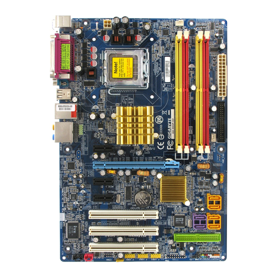
Page 8: Ga-965P-Ds3/S3 Motherboard Layout
88E8056 PCIE_16 PCIE_1 PCIE_2 CODEC PCI1 PCI2 PCI3 CD_IN SPDIF_I ATX_12V LGA775 Intel P965 ® CLR_CMOS BATTERY F_USB1 F_USB2 F_USB3 - 8 - CPU_FAN PWR_FAN Intel ICH8 ® GSATAII0 GIGABYTE SATA2 GSATAII1 BIOS IDE1 F_PANEL PWR_LED SATAII0 SATAII1 SATAII2 SATAII3... -
Page 9: Block Diagram
Block Diagram PCIe CLK (100 MHz) PCI Express x16 2 SATA 3Gb/s ATA 33/66/100/133 IDE Channel GIGABYTE SATA2 PCI Express Bus PCIe CLK (100 MHz) 3 PCI Express x1 PCI Bus 3 PCI PCICLK (33 MHz) (Note 1) Applies only when the GA-965P-DS3/S3 motherboard (rev. 3.3) is installed with a 1333 MHz FSB processor. - Page 10 - 10 -...
-
Page 11: Chapter 1 Hardware Installation
2. Damage as a result of violating the conditions recommended in the user manual. 3. Damage due to improper installation. 4. Damage due to use of uncertified components. 5. Damage due to use exceeding the permitted parameters. 6. Product determined to be an unofficial Gigabyte product. - 11 - Hardware Installation... -
Page 12: Feature Summary
1 FDD connector, allowing connection of 1 FDD device 4 SATA 3Gb/s connectors (SATAII0,1, 2, 3), allowing connection of 4 SATA 3Gb/s devices Onboard GIGABYTE SATA2 chip 1 IDE connector (UDMA 33/ATA 66/ATA 100/ATA 133), allowing con- nection of 2 IDE devices... - Page 13 667 MHz or 833 MHz, depending on the memory being installed. (Note 2) To use a DDRII 800/667 memory module on the motherboard, you must install a 1333/1066/ 800 MHz FSB processor. (Note 3) EasyTune functions may vary depending on different motherboards. (Note 3) - 13 - Hardware Installation...
-
Page 14: Installation Of The Cpu And Cpu Cooler
Installation of the CPU and CPU Cooler Before installing the CPU, please comply with the following conditions: Please make sure that the motherboard supports the CPU. Please take note of the one indented corner of the CPU. If you install the CPU in the wrong direction, the CPU will not insert properly. -
Page 15: Installation Of The Cpu Cooler
1-3-2 Installation of the CPU Cooler Fig.1 Please apply an even layer of heat paste on the surface of the installed CPU. Fig. 3 Place the CPU cooler atop the CPU and make sure the push pins aim to the pin hole on the motherboard.Pressing down the push pins diagonally. -
Page 16: Installation Of Memory
Installation of Memory Before installing the memory modules, please comply with the following conditions: 1. Please make sure that the memory used is supported by the motherboard. It is recommended that memory of similar capacity, specifications and brand be used. 2. - Page 17 Dual Channel Memory Configuration The GA-965P-DS3/S3 supports the Dual Channel Technology. After operat- ing the Dual Channel Technology, the bandwidth of memory bus will double. The GA-965P-DS3/S3 includes 4 DIMM sockets, and each Channel has two DIMM sockets as following: Channel 0 : DDRII1, DDRII2 Channel 1 : DDRII3, DDRII4 If you want to operate the Dual Channel Technology, please note the following explanations...
-
Page 18: Installation Of Expansion Cards
Installation of Expansion Cards You can install your expansion card by following the steps outlined below: Read the related expansion card's instruction document before install the expansion card into the computer. Remove your computer's chassis cover, screws and slot bracket from the computer. Press the expansion card firmly into expansion slot in motherboard. -
Page 19: I/O Back Panel Introduction
I/O Back Panel Introduction PS/2 Keyboard and PS/2 Mouse Connector To install a PS/2 port keyboard and mouse, plug the mouse to the upper port (green) and the keyboard to the lower port (purple). LPT (Parallel Port) The parallel port allows connection of a printer, scanner and other peripheral devices. COAXIAL (S/PDIF Out) The SPDIF coaxial output port is capable of providing digital audio to external speakers or compressed AC3 data to an external Dolby Digital Decoder via a coaxial cable. -
Page 20: Connectors Introduction
Line Out (Front Speaker Out) The default Line Out (Front Speaker Out) jack. Stereo speakers, earphone or front surround speakers can be connected to Line Out (Front Speaker Out) jack. MIC In The default MIC In jack. Microphone must be connected to MIC In jack. In addition to the default speakers settings, the perform different functions via the audio software. - Page 21 1/2) ATX_12V/ATX (Power Connector) With the use of the power connector, the power supply can supply enough stable power to all the components on the motherboard. Before connecting the power connector, please make sure that all components and devices are properly installed. Align the power connector with its proper location on the motherboard and connect tightly.
- Page 22 3/4/5) CPU_FAN / SYS_FAN / PWR_FAN (Cooler Fan Power Connector) The cooler fan power connector supplies a +12V power voltage via a 3-pin/4-pin (only for CPU_FAN/SYS_FAN) power connector and possesses a foolproof connection design. Most coolers are designed with color-coded power connector wires. A red power connector wire indicates a positive connection and requires a +12V power voltage.
- Page 23 7) FDD (Floppy Connector) The FDD connector is used to connect the FDD cable while the other end of the cable connects to the FDD drive. The types of FDD drives supported are: 360 KB, 720 KB, 1.2 MB, 1.44 MB and 2.88 MB.
- Page 24 SATA 3Gb/s can provide up to 300MB/s transfer rate. Please refer to the BIOS setting for the Serial ATA and install the proper driver in order to work properly. 10) GSATAII0/1 (SATA 3Gb/s Connector, Controlled by GIGABYTE SATA2) SATA 3Gb/s can provide up to 300MB/s transfer rate. Please refer to the BIOS setting for the Serial ATA and install the proper driver in order to work properly.
-
Page 25: Front Panel Jumper
11) F_PANEL (Front Panel Jumper) Please connect the power LED, PC speaker, reset switch and power switch etc. of your chassis front panel to the F_PANEL connector according to the pin assignment below. HD (IDE Hard Disk Active LED) (Blue) SPEAK (Speaker Connector) (Amber) RES (Reset Switch) - Page 26 12) F_AUDIO (Front Audio Connector) This connector supports either HD (High Definition) or AC97 front panel audio module. If you wish to use the front audio function, connect the front panel audio module to this connector. Check the pin assignments carefully while you connect the front panel audio module. Incorrect connection between the module and connector will make the audio device unable to work or even damage it.
- Page 27 13) PWR_LED The PWR_LED connector is connected with the system power indicator to indicate whether the system is on/off. It will blink when the system enters suspend mode (S1). 14) CD_IN (CD IN) Connect CD-ROM or DVD-ROM audio out to the connector. Pin No.
- Page 28 15) SPDIF_I (S/PDIF In Connector) Use S/PDIF IN feature only when your device has digital output function. Be careful with the polarity of the SPDIF_I connector. Check the pin assignment carefully while you connect the S/PDIF cable, incorrect connection between the cable and connector will make the device unable to work or even damage it.
- Page 29 17) CI (Chassis Intrusion, Case Open) This 2-pin connector allows your system to detect if the chassis cover is removed. You can check the "Case Opened" status in BIOS Setup. 18) CLR_CMOS (Clear CMOS) You may clear the CMOS data to its default values by this header. To clear CMOS, temporarily short the two pins.
- Page 30 19) BATTERY GA-965P-DS3/S3 Motherboard Danger of explosion if battery is incorrectly replaced. Replace only with the same or equivalent type recommended by the manufacturer. Dispose of used batteries according to the manufacturer's instructions. If you want to erase CMOS... 1. Turn off the computer and unplug the power cord. 2.
-
Page 31: Chapter 2 Bios Setup
CMOS SETUP screen. You can enter the BIOS setup screen by pressing "Ctrl + F1". If you wish to upgrade to a new BIOS, either Gigabyte's Q-Flash or @BIOS utility can be used. Q-Flash allows the user to quickly and easily update or backup BIOS without entering the operating system. -
Page 32: The Main Menu (Example Bios Ver.: Ga-965P-Ds3, F10A)
Startup Screen: <TAB>: POST Screen <DEL>: BIOS Setup/Q-Flash <F9>: XpressRecovery2 <F12>: Boot Menu <TAB> : POST Screen Press the TAB key to see BIOS POST screen. (To show the BIOS POST screen at system startup, refer to the instructions on the Full Screen LOGO Show item on page 37.) <DEL>... - Page 33 BIOS Setting Recovery F11 : Save CMOS to BIOS This function allows you to make a record of the current CMOS settings as a profile. You can create up to 8 profiles (Profile 1-8) and give each of them a name. F12 : Load CMOS from BIOS If your system becomes unstable and you load the default BIOS settings, you can use this function to reload the CMOS settings with a CMOS settings profile created before, without the hassles of...
-
Page 34: Standard Cmos Features
Standard CMOS Features CMOS Setup Utility-Copyright (C) 1984-2006 Award Software Date (mm:dd:yy) Time (hh:mm:ss) IDE Channel 0 Master IDE Channel 1 Master IDE Channel 2 Master IDE Channel 3 Master IDE Channel 4 Master IDE Channel 4 Slave IDE Channel 5 Master IDE Channel 5 Slave Drive A Floppy 3 Mode Support... - Page 35 Access Mode Use this to set the access mode for the hard drive. The two options are: Large/Auto(default:Auto) Capacity Capacity of currently installed hard disk. Cylinder Number of cylinders Head Number of heads Precomp Write precomp Landing Zone Landing zone Sector Number of sectors Drive A...
-
Page 36: Advanced Bios Features
Advanced BIOS Features CMOS Setup Utility-Copyright (C) 1984-2006 Award Software Hard Disk Boot Priority First Boot Device Second Boot Device Third Boot Device Password Check HDD S.M.A.R.T. Capability CPU Hyper-Threading (Note) Limit CPUID Max. to 3 (Note) No-Execute Memory Protect (Note) CPU Enhanced Halt (C1E) (Note) - Page 37 HDD S.M.A.R.T. Capability This feature allows your hard disk to report read/write errors and to issue warnings when third- party hardware monitor utility is installed. Enabled Enable HDD S.M.A.R.T. capability. Disabled Disable HDD S.M.A.R.T. capability. (Default value) CPU Hyper-Threading (Note) Enabled Enable CPU Hyper Threading Feature.
-
Page 38: Integrated Peripherals
Integrated Peripherals CMOS Setup Utility-Copyright (C) 1984-2006 Award Software SATA AHCI Mode SATA Port0-3 Native Mode USB Controller USB 2.0 Controller USB Keyboard Support USB Mouse Support Legacy USB storage detect Azalia Codec Onboard H/W LAN SMART LAN Onboard LAN Boot ROM Onboard SATA/IDE Device Onboard SATA/IDE Ctrl Mode Onboard Serial Port 1... - Page 39 Onboard H/W LAN Enabled Enable Onboard H/W LAN function. (Default value) Disabled Disable this function. SMART LAN (LAN Cable Diagnostic Function) CMOS Setup Utility-Copyright (C) 1984-2006 Award Software Start detecting at Port... Pair1-2 Status = Normal / Length Pair3-6 Status = Normal / Length Pair4-5 Status =...
- Page 40 Disabled Disable this function. (Default value) Enabled Enable this function. Onboard SATA/IDE Device This function allows users to enable or disable the SATA/IDE ports controlled by the GIGABYTE SATA2 controller. Enabled Enable this function. (Default value) Disabled Disable this function.
-
Page 41: Power Management Setup
Power Management Setup CMOS Setup Utility-Copyright (C) 1984-2006 Award Software ACPI Suspend Type Soft-Off by PWR-BTTN PME Event Wake Up Power On by Ring Resume by Alarm x Date (of Month) Alarm x Time (hh:mm:ss) Alarm HPET Support (Note) HPET Mode (Note) Power On By Mouse Power On By Keyboard... - Page 42 HPET Mode (Note) 32-bit mode Select 32-bit mode for 32-bit Vista operating system. (Default value) 64-bit mode Select 64-bit mode for 64-bit Vista operating system. Power On By Mouse Disabled Disable this function. (Default value) Double Click Double the left button on the PS/2 mouse to power on the system. Power On By Keyboard Disabled Disable this function.
-
Page 43: Pnp/Pci Configurations
PnP/PCI Configurations CMOS Setup Utility-Copyright (C) 1984-2006 Award Software PCI1 IRQ Assignment PCI2 IRQ Assignment PCI3 IRQ Assignment : Move Enter: Select F5: Previous Values PCI1 IRQ Assignment Auto 3,4,5,7,9,10,11,12,14,15 PCI2 IRQ Assignment Auto 3,4,5,7,9,10,11,12,14,15 PCI3 IRQ Assignment Auto 3,4,5,7,9,10,11,12,14,15 PnP/PCI Configurations [Auto] [Auto]... -
Page 44: Pc Health Status
PC Health Status CMOS Setup Utility-Copyright (C) 1984-2006 Award Software Reset Case Open Status Case Opened Vcore DDR18V +3.3V +12V Current System Temperature Current CPU Temperature Current CPU FAN Speed Current SYSTEM FAN Speed Current POWER FAN Speed CPU Warning Temperature CPU FAN Fail Warning SYSTEM FAN Fail Warning POWER FAN Fail Warning... - Page 45 Smart FAN Control Method Auto BIOS sets the optimal CPU fan speed automatically. (Default value) Intel(R) QST Control the fan speed with Intel Legacy CPU fan runs at different speed depending on CPU temperature. Disable CPU fan runs at full speed. Smart FAN Control Mode Auto BIOS autodetects the type of CPU fan you installed and sets the optimal fan...
-
Page 46: Mb Intelligent Tweaker(M.i.t.)
MB Intelligent Tweaker(M.I.T.) CMOS Setup Utility-Copyright (C) 1984-2006 Award Software Robust Graphics Booster CPU Clock Ratio (Note 1) CPU Host Clock Control x CPU Host Frequency (Mhz) PCI Express Frequency (Mhz) C.I.A. 2 System Memory Multiplier (SPD) Memory Frequency (Mhz) 533 High Speed DRAM DLL Settings ******** System Voltage Optimized System Voltage Control... - Page 47 CPU Host Frequency (Mhz) 100 MHz ~ 700 MHz If you use a 533 MHz FSB processor, set "CPU Host Frequency" to 133 MHz. If you use an 800 MHz FSB processor, set "CPU Host Frequency" to 200 MHz. If you use a 1066 MHz FSB processor, set "CPU Host Frequency" to 266 MHz. If you use a 1333 MHz FSB processor, set "CPU Host Frequency"...
- Page 48 System Voltage Control This item allows the users to decide whether to configure system voltage settings by their requirements. Auto Lets the BIOS configure all system voltage settings. Manual Manually configure the system voltage settings. (Default value) DDR2 OverVoltage Control Please note that by overclocking your system through the increase of the DIMM voltage, damage to the memory may occur.
-
Page 49: Load Fail-Safe Defaults
Load Fail-Safe Defaults CMOS Setup Utility-Copyright (C) 1984-2006 Award Software Standard CMOS Features Advanced BIOS Features Integrated Peripherals Power Management Setup PnP/PCI Configurations PC Health Status MB Intelligent Tweaker(M.I.T.) ESC: Quit F8: Q-Flash Fail-Safe defaults contain the most appropriate values of the system parameters that allow minimum system performance. -
Page 50: Set Supervisor/User Password
2-10 Set Supervisor/User Password CMOS Setup Utility-Copyright (C) 1984-2006 Award Software Standard CMOS Features Advanced BIOS Features Integrated Peripherals Power Management Setup PnP/PCI Configurations Enter Password: PC Health Status MB Intelligent Tweaker(M.I.T.) ESC: Quit F8: Q-Flash When you select this function, the following message will appear at the center of the screen to assist you in creating a password. -
Page 51: Save & Exit Setup
2-11 Save & Exit Setup CMOS Setup Utility-Copyright (C) 1984-2006 Award Software Standard CMOS Features Advanced BIOS Features Integrated Peripherals Save to CMOS and EXIT (Y/N)? Y Power Management Setup PnP/PCI Configurations PC Health Status MB Intelligent Tweaker(M.I.T.) ESC: Quit F8: Q-Flash Type "Y"... - Page 52 GA-965P-DS3/S3 Motherboard - 52 -...
-
Page 53: Chapter 3 Install Drivers
Chapter 3 Install Drivers Pictures below are shown in Windows XP. Insert the driver CD-title that came with your motherboard into your CD-ROM drive, the driver CD-title will auto start and show the installation guide. If not, please double click the CD-ROM device icon in "My computer", and execute the Run.exe. -
Page 54: Software Applications
Software Applications This page displays all the tools that Gigabyte developed and some free software, you can choose anyone you want and press "install" to install them. Driver CD Information This page lists the contents of software and drivers in this CD-title. -
Page 55: Hardware Information
Hardware Information This page lists all device you have for this motherboard. Contact Us Please see the last page for details. - 55 - Install Drivers... - Page 56 GA-965P-DS3/S3 Motherboard - 56 -...
-
Page 57: Chapter 4 Appendix
Enters the PC Health setting page Confirmation and Execution button Toggles between Easy and Advance Mode Display panel of CPU frequency Shows the current functions status Log on to GIGABYTE website Display EasyTune 5 Help file Quit or Minimize EasyTune 5 software... -
Page 58: Xpress Recovery2 Introduction
4-1-2 Xpress Recovery2 Introduction Xpress Recovery2 is designed to provide quick backup and restora- tion of hard disk data. Supporting Microsoft operating systems including Windows XP/2000/NT/98/Me and DOS, and file systems including FAT16, FAT32, and NTFS, Xpress Recovery2 is able to back up data on hard disks on PATA and SATA IDE controllers. - Page 59 2. It is normal that data backup takes longer time than data restoration. 3. Xpress Recovery2 is compliant with the GPL regulations. 4. On a few motherboards based on Nvidia chipsets, BIOS update is required for Xpress Recovery2 to correctly identify RAID and SATA IDE mode. Please contact your motherboard manufacturer.
-
Page 60: Flash Bios Method Introduction
Before Use: Follow the steps below before using Q-Flash to update BIOS: 1. From GIGABYTE's website, download the latest compressed BIOS update file that matches your motherboard model. 2. Extract the file and save the new BIOS file (e.g. 965PDS3.F1) to your floppy disk, USB flash drive, or hard disk. - Page 61 c . Select the BIOS file and press ENTER. Make sure again the BIOS file matches your motherboard model. Step 2: The process of system reading the BIOS file from the floppy disk is displayed on the screen. When the message "Are you sure to update BIOS?" appears, press ENTER. The BIOS update will begin and the current process will be displayed.
- Page 62 Please search for BIOS unzip file, downloading from internet or any other methods (such as: 965PDS3.F1). Complete update process following the instruction. GA-965P-DS3/S3 Motherboard Utility Fig 2. Installation Complete and Run @BIOS Click Start/ Programs/ Gigabyte/ BIOS/ @BIOS Fig 4. Select the desired @BIOS server - 62 -...
- Page 63 Otherwise, your system won't boot. III. In method I, if the BIOS file you need cannot be found in @BIOS Gigabyte's web site for downloading and updating it according to method II. IV. Please note that any interruption during updating will cause system unbooted.
-
Page 64: Configuring Sata Hard Drive(S) (Controller: Gigabyte Sata2)
4-1-4 Configuring SATA Hard Drive(s) (Controller: GIGABYTE SATA2) To configure SATA hard drive(s), follow the steps below: (1) Install SATA hard drive(s) in your system. (2) Configure SATA controller mode and boot sequence in BIOS Setup. (3) Configure RAID array in RAID BIOS. - Page 65 (2) Configuring SATA controller mode and boot sequence in BIOS Setup Make sure to configure the SATA controller mode correctly in system BIOS Setup and set the first boot device. Step 1: Turn on your computer and press Del to enter BIOS Setup during POST (Power-On Self Test). In BIOS Setup, go to Integrated Periperals, ensure that the Onboard SATA/IDE Device is enabled.
- Page 66 Step 2: To boot from Windows installation CD-ROM disk, set First Boot Device under the Advanced BIOS Features menu to CDROM (Figure 2). CMOS Setup Utility-Copyright (C) 1984-2006 Award Software Hard Disk Boot Priority First Boot Device Second Boot Device Third Boot Device Password Check HDD S.M.A.R.T.
- Page 67 Press <Ctrl-G> to enter RAID Setup Utility ... In the main screen of the GIGABYTE RAID BIOS utility (Figure 4), use the UP or DOWN ARROW key to highlight through choices. Highlight the item that you wish to execute and press ENTER.
- Page 68 A. Create Array: In the main screen, press ENTER on the Create RAID Disk Drive item. Then the RAID creation screen appears (Figure 5). GIGABYTE Technology Corp. PCIE-to-SATAII/IDE RAID Controller BIOSv1.06.53 [ Create New RAID ] Name: GRAID Level: 0-Stripe...
- Page 69 4. Set Block Size (only for RAID 0): Under the Block item, use the UP or DOWN ARROW key to select the block size (Figure 7), ranging from 4K to 128K. Press ENTER when finished. GIGABYTE Technology Corp. PCIE-to-SATAII/IDE RAID Controller BIOSv1.06.53 [ Create New RAID ]...
- Page 70 6. Confirm Creation: After all of the items are configured, the selection bar automatically jumps to the Confirm Creation item. When prompted to confirm your selections (Figure 9), press Y to confirm or N to abort. GIGABYTE Technology Corp. PCIE-to-SATAII/IDE RAID Controller BIOSv1.06.53 [ Create New RAID ] Name: GRAID...
- Page 71 RAID Disk Drive List block. Select the array and press ENTER. A small window displaying the array information will appear in the center of the screen (Figure 11). GIGABYTE Technology Corp. PCIE-to-SATAII/IDE RAID Controller BIOSv1.06.53 [ Main Menu ]...
- Page 72 RAID Disk Drive List block. Press the SPACEBAR on the array to be deleted; a small triangle will appear to mark the selected array (Figure 13). Press Del. GIGABYTE Technology Corp. PCIE-to-SATAII/IDE RAID Controller BIOSv1.06.53 [ Main Menu ]...
- Page 73 Step 2: When the controller menu (Figure 16) appears, remove the startup disk and insert the blank formatted disk. Select the controller driver by pressing the corresponding letter from the menu. For example, from the menu in Figure 16, press E to select (E) GIGABYTE SATA-RAID Driver 32Bit if you wish to install Windows XP (32-bit) .
- Page 74 (5) Installing SATA controller driver during OS installation (Required for AHCI and RAID Mode) Now that you have prepared the SATA driver disk and configured BIOS settings, you are ready to install Windows 2000/XP onto your SATA hard drive with the SATA driver. The following is an example of Windows XP installation.
- Page 75 When Setup correctly recognizes the driver in the floppy disk, a controller menu similar to Figure 20 below will appear. Use the ARROW keys to select one of the items displayed depending on the operating system to be installed. For example, select GIGABYTE GBB363 RAID Controller (Windows 2K/XP/2003) if you wish to install Windows XP.
- Page 76 After the SATA controller driver installation is completed, you can proceed with the Windows 2000/XP installation. WindowsXP Professional Setup Welcome to Setup. This port of the Setup program prepares Microsoft(R) Windows (R) XP to run on your computer. To set up Windows XP now, press ENTER. To repair a Windows XP installation using Recovery Console, press R.
-
Page 77: 4- / 6- / 8- Channel Audio Function Introduction
The default speaker settings for the 6 audio jacks are as shown in the picture to the right. The jack retasking capability supported by HD Audio allows users to change the function for each audio jack by the audio software provided. For example, if a rear speaker is plugged into the center/subwoofer speaker out jack, you can change the center/ subwoofer speaker out jack to fucntion as a rear... - Page 78 STEP 2: In the Audio Control Panel, click the Audio I/O tab. In the upper left list, click 2CH Speaker. STEP 3: After a speaker or headphone is plugged into the rear Line Out jack, a small window will pop up and ask you what type of equipment is connected.
- Page 79 STEP 3: After plugging in 4-channel speakers to the rear speaker jacks, a small window will pop up and ask you what type of equipment is connected. Choose a device depending on the type of speaker connected (4-channel audio consists of Front Speaker Out (Line Out) and Rear Speaker Out) and then click OK.
- Page 80 8 Channel Audio Setup STEP 1 : After installation of the audio driver, you should find an Audio Manager icon in your system tray (you can also find the icon in Control Panel). Double- click the icon to open the Audio Control Panel. STEP 2: In the Audio Control Panel, click the Audio I/O tab.
- Page 81 Sound Effect Configuration: At the Sound Effect menu, users can adjust sound option settings as desired. AC'97 Audio Configuration: To enable the front panel audio connector to sup- port AC97 Audio mode, go to the Audio Control Panel and click the Audio I/O tab. In the ANA- LOG area, click the Tool icon and then select the Disable front panel jack detection check box.
-
Page 82: Troubleshooting
Below is a collection of general asked questions. To check general asked questions based on a specific motherboard model, please log on to GIGABYTE's website. Question 1: I cannot see some options that were included in previous BIOS after updating BIOS. Why? Answer: Some advanced options are hidden in new BIOS version. - Page 83 - 83 - Appendix...
- Page 84 GA-965P-DS3/S3 Motherboard - 84 -...
- Page 85 - 85 - Appendix...
- Page 86 GIGA-BYTE TECHNOLOGY CO., LTD. Address: No.6, Bau Chiang Road, Hsin-Tien, Taipei 231, Taiwan TEL: +886-2-8912-4888 FAX: +886-2-8912-4003 Tech. and Non-Tech. Support (Sales/Marketing) : http://ggts.gigabyte.com.tw WEB address (English): http://www.gigabyte.com.tw WEB address (Chinese): http://www.gigabyte.tw U.S.A. G.B.T. INC. TEL: +1-626-854-9338 FAX: +1-626-854-9339 Tech. Support: http://rma.gigabyte-usa.com...
- Page 87 Germany G.B.T. TECHNOLOGY TRADING GMBH WEB address : http://www.gigabyte.de U.K. G.B.T. TECH. CO., LTD. WEB address : http://www.giga-byte.co.uk The Netherlands GIGA-BYTE TECHNOLOGY B.V. WEB address : http://www.giga-byte.nl France GIGABYTE TECHNOLOGY FRANCE WEB address : http://www.gigabyte.fr Italy WEB address : http://www.giga-byte.it...
- Page 88 - 88 -...
Need help?
Do you have a question about the GA-965P-S3 and is the answer not in the manual?
Questions and answers