Table of Contents
Advertisement
Quick Links
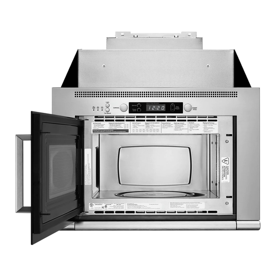
MICROWAVE HOOD COMBINATION
This product is suitable for use above electric or gas cooking products up to and including 24" (61.0 cm) wide. See "Installation
Requirements" section for further details.
BEFORE BEGINNING PLEASE NOTE:
Read these Installation Instructions in their entirety before starting.
Vent system is required for this installation. See "Venting Requirements" section.
When installation is complete, the microwave oven's galvanized upper component housing will be visible above the microwave oven.
The housing may be covered using a stainless steel filler panel (not provided) or with customized cabinetry. See "Complete
Installation" section.
ENSEMBLE FOUR À MICRO-ONDES/HOTTE
Ce produit peut être installé au-dessus de produits de cuisson électriques ou à gaz d'une largeur maximale de 24" (61 cm). Voir la section
"Exigences d'installation" pour plus de détails.
AVANT DE COMMENCER, NOTER LES POINTS SUIVANTS :
Lire la totalité de ces instructions d'installation avant de commencer.
Cette installation nécessite un système d'évacuation. Voir la section "Exigences du circuit d'évacuation".
Une fois l'installation terminée, le compartiment supérieur galvanisé du four à micro-ondes sera apparent au-dessus du four à micro-
ondes. Le compartiment peut être recouvert d'un panneau de remplissage en acier inoxydable (non fourni) ou d'un élément de
placard personnalisé. Voir la section "Achever l'installation".
MICROWAVE HOOD COMBINATION SAFETY .....................2
INSTALLATION REQUIREMENTS ...........................................2
Tools and Parts.......................................................................2
Location Requirements ..........................................................3
Product Dimensions ..............................................................3
Electrical Requirements..........................................................4
Venting Requirements ............................................................4
INSTALLATION INSTRUCTIONS .............................................6
Install L-Brackets ....................................................................6
Prepare Upper Cabinet...........................................................6
Install Stainless Steel Panel Kit (optional steps) ....................6
Install the Microwave Oven ....................................................7
Install Damper Assembly........................................................7
Install Bottom Plate ................................................................8
Install Rear Trim ......................................................................8
Install Visor..............................................................................9
Install Grease Filter .................................................................9
Complete Installation............................................................10
ASSISTANCE ...........................................................................11
Replacement Parts ...............................................................11
Kits ........................................................................................11
W11174207A
INSTALLATION INSTRUCTIONS
INSTRUCTIONS D'INSTALLATION
Table of Contents / Table des matières
EXIGENCES D'INSTALLATION........................................................ 12
Outils et pièces............................................................................... 12
Exigences d'emplacement............................................................. 13
Dimensions du produit ................................................................... 13
Spécifications électriques .............................................................. 14
Exigences du circuit d'évacuation ................................................. 14
INSTRUCTIONS D'INSTALLATION ................................................. 16
Installation des supports en "L" ..................................................... 16
Préparation du placard mural......................................................... 16
Installation du panneau en acier inoxydable (étapes facultatives) .........17
Installation du four à micro-ondes ................................................. 17
Installation du clapet anti-retour .................................................... 18
Installation de la plaque inférieure.................................................. 18
Installation de la garniture arrière................................................... 19
Installation de l'écran mobile.......................................................... 19
Installation du filtre à charbon (pour une installation avec
recyclage uniquement) ................................................................... 20
Installation du filtre à graisse.......................................................... 20
Achever l'installation....................................................................... 21
ASSISTANCE ..................................................................................... 22
Pièces de rechange........................................................................ 22
Ensembles ...................................................................................... 22
Advertisement
Table of Contents

Related Manuals for Whirlpool UMH50008HS0


Summary of Contents for Whirlpool UMH50008HS0
-
Page 1: Table Of Contents
MICROWAVE HOOD COMBINATION INSTALLATION INSTRUCTIONS This product is suitable for use above electric or gas cooking products up to and including 24" (61.0 cm) wide. See “Installation Requirements” section for further details. BEFORE BEGINNING PLEASE NOTE: Read these Installation Instructions in their entirety before starting. Vent system is required for this installation. -
Page 2: Microwave Hood Combination Safety
MICROWAVE HOOD COMBINATION SAFETY Your safety and the safety of others are very important. We have provided many important safety messages in this manual and on your appliance. Always read and obey all safety messages. This is the safety alert symbol. This symbol alerts you to potential hazards that can kill or hurt you and others. -
Page 3: Location Requirements
Parts Supplied Installation Dimensions For information on ordering, see “Replacement Parts” section. NOTE: The grounded 3 prong outlet must be inside the upper cabinet. See “Electrical Requirements” section. 21" (53.3 cm) min. ⁷⁄₈ 21⁵⁄₈" (54.9 cm)** " (60.6 cm) min.* ¹⁄₈... -
Page 4: Electrical Requirements
Electrical Requirements Venting Requirements This section is intended for architectural designer and WARNING builder/contractor reference only. NOTES: If installing for recirculation, venting must be routed up and out through an exhaust register (not provided) in a kitchen soffit. A charcoal filter kit (not provided) should be used. See “Assistance”... - Page 5 Rectangular to Round Transition Recommended Vent Length NOTE: The minimum 3" (7.6 cm) clearance must exist between the top of the damper assembly and the rectangular to round A 3¹⁄₄ x 10 (8.3 x 25.4 cm) rectangular or 6 (15.2 cm) round vent "...
-
Page 6: Installation Instructions
INSTALLATION INSTRUCTIONS 4. Using 2 mm drill, drill holes marked in Step 3. Install L-Brackets 5. Secure L-brackets to side cabinets with ten 16 mm wood screws, 5 in each L-bracket. 1. Measure and mark a line on each of the side cabinets at least 18¹⁄₈"... -
Page 7: Install The Microwave Oven
5. Place a washer on each 16 mm round-head bolt, then install each bolt through the L-bracket base slot, into the mounting Install the Microwave Oven hole in the bottom of the microwave oven. Do not overtighten. 1. Remove any contents of the microwave oven. WARNING Excessive Weight Hazard Use two or more people to move and install... -
Page 8: Install Bottom Plate
Install Bottom Plate Install Rear Trim NOTE: Pre-tap front mounting holes prior to bottom plate 1. Measure the distance from the rear wall to the front edge of attachment. (See Step 2.) the rear frame of the bottom plate. 1. Hook the heads of the screws through the keyholes at the back of the microwave oven bottom, as shown, then slide bottom plate back. -
Page 9: Install Visor
2. Insert wire rods to hold charcoal filter in place. Install Visor 1. Open visor, and slide its mounting tray – with the mounting tray edges facing down – into the slot between the microwave oven bottom and the bottom plate, as shown. A. -
Page 10: Complete Installation
Complete Installation 1. Connect all venting and ductwork necessary for the type of NOTE: After installation is complete, the upper component installation (roof venting, wall venting or recirculation). See housing on the top of the microwave oven will be visible (Figure 1). “Venting Requirements”... -
Page 11: Assistance
ASSISTANCE Call your authorized dealer or service center. When you call, you will need the microwave oven model number and serial number. Both numbers can be found on the model and serial number plate, which is located behind the microwave oven door on the front frame of the microwave oven. -
Page 12: Sécurité De L'ensemble Four À Micro-Ondes/Hotte
12/17 ©2017. Used under license in Canada. All rights reserved. Printed in Italy W11174207A Utilisé sous licence au Canada. Tous droits réservés. Imprimé en Italie...