
Related Manuals for Toshiba HCV-1JBU


Summary of Contents for Toshiba HCV-1JBU
- Page 1 Document: VF010H07A Rev. 1 INSTRUCTION MANUAL INSTALLATION - OPERATION - MAINTENANCE HCV-1JBU Vacuum Contactor, 1.5kV - 600A HCV-1KAU Vacuum Contactor, 1.5kV - 720A Issued: 4/20 Manufactured in the USA...
- Page 3 INSTRUCTION MANUAL For the Installation, Operation and Maintenance of HCV-1JBU Vacuum Contactor, 1.5kV – 600A HCV-1KAU Vacuum Contactor, 1.5kV – 720A Never attempt to install, operate, maintain or dispose of this equipment until WARNING you have first read and understood all of the relevant product warnings and user directions that are contained in this Instruction Manual.
-
Page 5: Safety
SAFETY Page 1 IMPORTANT MESSAGES Read this manual and follow its instructions. Signal words such as DANGER, WARNING and CAUTION will be followed by important safety information that must be carefully reviewed. Indicates a situation that will result in death, serious injury, and severe DANGER property damage if you do not follow instructions. - Page 6 Be trained in rendering first aid. SAFETY CODES Toshiba HCV-1JBU and HCV-1KAU vacuum contactors are designed and built in accordance with NEMA ICS 3-2, UL 508, CSA 22.2-14 and IEC 60470. Installations must comply with all applicable state and local codes, adhere to all applicable National...
- Page 7 SAFETY Page 3 HAZARDOUS VOLTAGE will cause severe injury, death, fire, explosion, and DANGER property damage. • Turn off and lock out Primary and Control Circuit Power before servicing. • Keep all panels and covers securely in place. • Never Defeat, Modify, or Bypass any Safety Interlocks •...
-
Page 8: Table Of Contents
Page 4 TABLE OF CONTENTS SAFETY ..............................1 INTRODUCTION ............................. 6 GENERAL DESCRIPTION ........................7 Components ..........................7 - Contactor Components ......................7 Indicators and Controls ........................ 8 - ON/OFF Indicator ........................8 RECEIVING, INSPECTION AND HANDLING ..................9 Receiving and Unpacking ......................9 Acceptance Inspection ......................... - Page 9 Page 5 Table 3 – Gap/Wipe Standard Values (contactor in new condition) ..........20 Vacuum Check ..........................21 - Toshiba Portable Vacuum Checker .................... 21 - Application of Test Voltage for Vacuum Check ................22 Electrical Service Life ........................23 Mechanical Service Life .......................
-
Page 10: Introduction
Page 6 INTRODUCTION It is the intent of this manual to provide a guide for safely installing, operating and maintaining Toshiba vacuum contactors. This manual consists of a section of general safety instructions and is marked throughout with warning symbols. Read this manual thoroughly before installation, operation and maintenance of this equipment. -
Page 11: General Description
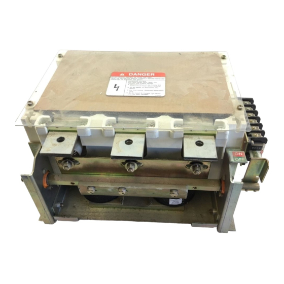
GENERAL DESCRIPTION Page 7 COMPONENTS The Toshiba HCV-1JB and HCV-1KA vacuum contactors described in this manual are suitable for use on systems of 1.5kV, 600A and 1.5kV, 720A respectively. Arc interruption is accomplished inside sealed vacuum interrupters mounted on track-resistant insulators. -
Page 12: Indicators And Controls
Page 8 GENERAL DESCRIPTION INDICATORS AND CONTROLS The following indicator is provided: On-Off Indicator - Indicates if the contactor is OFF (Green) or ON (Red). When the indicator reads OFF, the main contacts of the contactor are open. When the indication is ON, the main contacts are closed. -
Page 13: Receiving, Inspection And Handling
This may cause damage. File a claim with the carrier for any damaged or missing items and immediately notify the nearest Toshiba representative. Do not install or energize WARNING equipment that has been damaged. Damaged... -
Page 14: Installation
The tightening torque should be 120-150 kgf-cm (9-11 ft-lb). See Table 1 for tightening torque specifications. Toshiba HCV-1JBU and HCV-1KAU contactors are intended for use in usual service conditions as defined in NEMA ICS 1. The temperature of... -
Page 15: Ground Connections
INSTALLATION Page 11 Use two wrenches to The ground wire should be 8 AWG or larger. CAUTION torque the connection to Then reattach the terminal using the same bolt prevent applying excessive previously removed and torque to 9-11 ft-lb force to the terminal, which (120-150 kgf-cm). -
Page 16: Pre-Energization Check
Page 12 PRE-ENERGIZATION CHECK ELECTRICAL CHECKS GENERAL BEFORE ENERGIZING THE CONTACTOR for Electrical shock hazard. WARNING Do not touch energized the first time, follow the procedure below to verify that the equipment is properly installed and components during a test using auxiliary power. -
Page 17: Operation
OPERATION Page 13 MOVING THE CONTACTOR FROM THE OFF TO THE ON POSITION TO MOVE THE CONTACTOR TO THE ON POSITION: 1. Turn ON circuit control power to move the contactor to the ON position 2. Verify that the position indicator reads ON (Red). -
Page 18: Internal Connection Of The Normally Energized Type
Page 14 OPERATION LEGEND 52 CC …. Closing Coil T1-T4 ….. Terminal Block A1-A2…... Closing Supply AC/DC Vacuum Bottles Auxiliary Switch Drive Unit Closing Supply AC/DC Figure 8 – Internal Connection of the Normally Energized Type LEGEND 52 CC …. Closing Coil T1-T2 ….. -
Page 19: Standard Operation Circuit Of The Normally Energized Type
OPERATION Page 15 LEGEND R e m o t e 52 CC …. Closing Coil O F F O p e r a t i o n T1-T2 ….. Terminal Block S w i t c h GL ……… Green Light RL ………... -
Page 20: Maintenance
Page 16 MAINTENANCE MAINTENANCE PROGRAM MAINTENANCE RECORD In order to ensure continued reliable and safe Keep a permanent record of all maintenance operation of the equipment, a program of work. At a minimum, this record should include periodic maintenance must be established. information on: Operating and environmental conditions will usually dictate the frequency of inspection... -
Page 21: Inspection And Maintenance Types
MAINTENANCE Page 17 RECOMMENDED INSPECTION AND Table 1 - Tightening Torque MAINTENANCE TYPES Screw Nominal Tightening Torque Diameter NOTE: Refer to the SAFETY section of this manual for important information. 15-20 kgf-cm (13-17 in-lb) 1. Acceptance Inspection 30-40 kgf-cm (26-34 in-lb) This inspection confirms that the contactor is complete, correct... - Page 22 Vacuum See Electrical Check contact wear and Replace vacuum contact wear. Service Life (Page wipe. interrupter. 23). Vacuum Apply 10kV AC for 1 Check vacuum level by If breakdown occurs, level. minute. withstand voltage test. contact Toshiba.
- Page 23 Wipe with a clean, Frame and matter or dust, foreign matter or dry cloth. If Flanges damage breakage. damaged, contact Toshiba. Control Auxiliary See Table 3. Contact wear and wipe. Replace if wear or Circuits Switch Make sure there is no damage is dust.
- Page 24 Measure Measure dielectric 10kV AC or 14kV DC for If breakdown occurs, Strength main circuit strength between 1 minute. contact Toshiba. phases and between circuits and ground. Open/Close Perform open/close If not normal, check Operation operation by electric and repair. If...
-
Page 25: Vacuum Check
TEST EQUIPMENT: checker or AC hi-pot machine. Connect all the load side primary terminals together and Toshiba offers a compact vacuum checker (Type to the ground terminal of the vacuum checker or AC hi-pot machine. CI35-1D, Figure 11) which enables a quick and easy check on vacuum interrupter internal pressure. -
Page 26: Application Of Test Voltage For Vacuum Check
Page 22 MAINTENANCE CRITERIA: 1 minute 1. If a current flow above 5 milli-amperes is 10kV AC observed or if breakdown occurs, one or (14kV DC) more of the interrupters has insufficient vacuum and must be replaced. Exception: If the current exceeds 5 milli- Voltage amperes the first time the voltage is brought up, reduce the voltage to zero and increase it... -
Page 27: Electrical Service Life
The maximum number of open/close operations Stationary Core Detailed inspection and is 500,000 regardless of the magnitudes of the cleaning every 500,000 currents interrupted. Contact Toshiba for operations. information regarding replacement vacuum interrupters. Closing Coil... -
Page 28: Storage And Disposal
Page 24 DISPOSAL AND STORAGE STORAGE If the contactor is to be stored for any length of time prior installation, following precautions should be taken. 1. The original packing should be restored, if possible. 2. Do not subject the equipment to moisture or sunrays. -
Page 29: Specifications
SPECIFICATIONS Page 25 Table 5 - Ratings Items HCV-1JBU HCV-1KAU Rated Insulation Voltage Rated Operation Voltage 208-1500 Rated Operational Current Rated Frequency 50/60 Rated Making Current (close 100 times) (close 100 times) Rated Breaking Current 5.76 (close-open 25 times) (close-open 25 times) -
Page 30: Warranty And Limitation Of Liability
WARRANTY AND LIMITATION OF LIABILITY Page 26 Toshiba International Corporation ("Company") warrants that all equipment and parts described herein will be free from defects in materials and workmanship. THIS WARRANTY WILL EXPIRE EIGHTEEN (18) MONTHS AFTER THE DATE ON WHICH SUCH EQUIPMENT AND PARTS (EXCLUDING REPAIRED OR REPLACEMENT... - Page 31 TOSHIBA TOSHIBA INTERNATIONAL CORPORATION 13131 W. Little York Road, Houston, TX 77041, U.S.A. Tel: (713) 466-0277 Fax: (713) 466-8773 Printed in U.S.A.