Table of Contents
Troubleshooting

Related Manuals for NEC PE455UL


Summary of Contents for NEC PE455UL
- Page 1 Projector PE455UL/PE455WL/PE505XL User’s Manual Please visit our web site for User’s Manual in the latest version. https://www.nec-display.com/dl/en/pj_manual/lineup.html Model No. NP-PE455UL/NP-PE455WL/NP-PE505XL...
-
Page 2: Table Of Contents
Table of Contents Introduction ............................... iii Important Information .......................... iv 1. Check the product overview, supplied items and part names .......... 1 1-1. Introduction to the Projector ......................1 1-2. What’s in the Box? ..........................4 1-3. Part Names of the Projector ......................5 1-4. - Page 3 Table of Contents 5. Making Connections .......................... 83 5-1. Connecting Your Computer ......................83 5-2. Connecting to a DVD player and other AV devices ............... 86 5-3. Connecting to a Wired LAN ......................88 5-4. Connecting to a Wireless LAN (Optional: NP05LM series) ........... 89 5-5.
-
Page 4: Introduction
(3) Great care has been taken in the preparation of this user’s manual; however, should you notice any questionable points, errors or omissions, please contact us. (4) Notwithstanding article (3), NEC will not be responsible for any claims on loss of profit or other matters deemed to result from using the Projector. -
Page 5: Important Information
Important Information About the symbols To ensure safe and proper use of the product, this manual uses a number of symbols to prevent injury to you and others as well as damage to property. The symbols and their meanings are described below. Be sure to understand them thoroughly before reading this manual. - Page 6 Important Information Safety Cautions WARNING Handling the power cord • Please use the power cord supplied with this projector. If the supplied power cord does not satisfy requirements of your country’s safety standard, and voltage and current for your region, make sure to use the power cord that BE SURE TO DO conforms to and satisfies them.
- Page 7 Important Information Installing the Projector • This projector is designed to be used with a 100–240 V AC, 50/60 Hz power supply. Before using the projector, check that the power supply to which the projector is to be connected meets these requirements. BE SURE TO DO • Use a power outlet as the projector’s power supply. Do not connect the projector directly to electrical light wiring.
- Page 8 Important Information Installing suspended from the ceiling • Should special works be required, for example to suspend the projector from the ceiling, consult your dealer. Never try to install the projector yourself in such cases. The projector could CAUTION drop and cause injury. Suspending the projector from the ceiling requires sufficient ceiling strength to support the projector, and the building standards laws in your particular country must be followed.
- Page 9 Important Information About the projector’s light source • Do not look into the projector’s lens. Strong light that could damage your eyes is projected when the projector is operating. Be especially careful when children are around. PROHIBITION • Do not look at the projected light using optical devices (magnifying glasses, reflectors, etc.). Doing so could result in vision impairment. • Check that there is no one looking at the lens within the projection range before turning on the projector.
- Page 10 Important Information CAUTION Connecting the power cord to earth • This equipment is designed to be used in the condition of the power cord connected to earth. If the power cord is not connected to the earth, it may cause electric shock. Please make sure the power cord is earthed properly. BE SURE TO DO Do not use a 2-core plug converter adapter.
- Page 11 Important Information Handling batteries • Handle batteries with caution. Failure to do so could lead to fire, injury or contamination of the surroundings. - Do not short-circuit or take apart batteries or dispose of them in flames. PROHIBITION - Do not use batteries other than those specified. - Do not use new batteries together with old ones. - When inserting batteries, pay attention to the polarities (+ and −...
- Page 12 Important Information Laser Safety Caution WARNING CLASS 2 OF IEC 60825-1 SECOND EDITION LASER PRODUCT • LASER RADIATION - DO NOT STARE INTO BEAM. • Use of controls or adjustments or performance of procedures other than those specified herein may result in hazardous radiation exposure. • For USA This product is classified as Class 2 of IEC 60825-1 Second edition 2007-03. Complies with FDA performance standards for laser products except for deviations pursuant to Laser Notice No.
- Page 13 Important Information • The caution and the explanatory labels of the LASER PRODUCT in CLASS 2 conforming to IEC 60825-1 Second edition, and in Class 1 conforming to IEC 60825-1 Third edition are stuck on the below indicated positions. For USA Label For other regions...
- Page 14 Important Information Laser light radiation range The figure below shows the maximum radiation range of the laser light. Horizontal angle (unit: degree) Lens position Zoom Right most Center (Reference value) Left most Wide 33.0 22.3 33.0 Tele 21.8 14.2 21.8 Right Left Vertical angle (unit: degree)
- Page 15 FCC Information (for USA only) WARNING • The Federal Communications Commission does not allow any modifications or changes to the unit EXCEPT those specified by NEC Display Solutions of America, Inc. in this manual. Failure to comply with this government regulation could void your right to operate this equipment. • This equipment has been tested and found to comply with the limits for a Class B digital device, pursuant to Part 15 of the FCC Rules. These limits are designed to provide reasonable protec- tion against harmful interference in a residential installation.
- Page 16 Important Information Disposing of your used product In the European Union EU-wide legislation as implemented in each Member State requires that used electrical and electronic products carrying the mark (left) must be disposed of separately from normal household waste. This includes projectors and their electrical accessories. When you dispose of such products, please follow the guidance of your local authority and/or ask the shop where you purchased the product.
- Page 17 Important Information Cautions for ensuring the projector’s performance • Do not install in places subject to vibrations or shocks. If installed in places where the vibrations from power sources and the like are conveyed, or in vehicles or on vessels, etc. the projector could be affected by vibrations or shocks that may dam- age internal parts and lead to malfunction.
- Page 18 Important Information • Take measures to prevent external light from shining on the screen. Make sure only the light from the projector shines on the screen. The less external light on the screen, the higher the contrast and the more beautiful the images. • About screens Images will not be clear if there is dirt, scratches, discoloration, etc. on your screen. Handle the screen with care, protecting it from volatile substances, scratches and dirt.
- Page 19 To control the projector from an external device, select [OFF] for [AUTO POWER OFF]. (→ page 78) Model Number of Wireless LAN unit Wireless LAN unit is an optional item. To find the appropriate model to your area, please visit the company website: URL: https://www.nec-display.com/global/support/index.html xviii...
- Page 20 Important Information Trademarks • MultiPresenter is a trademark or registered trademark of NEC Display Solutions, Ltd. in Japan and other countries. • Apple, Mac, MacBook, and iMac are trademarks of Apple Inc. registered in the U.S. and other countries. • Microsoft, Windows, and PowerPoint are either a registered trademark or trademark of Microsoft Corporation in the United States and/or other countries. • The terms HDMI and HDMI High-Definition Multimedia Interface, and the HDMI Logo are trade- marks or registered trademarks of HDMI Licensing Administrator, Inc. in the United States and other countries. • PJLink trademark and logo are trademarks applied for registration or are already registered in Japan, the United States of America and other countries and areas.
-
Page 21: Check The Product Overview, Supplied Items And Part Names
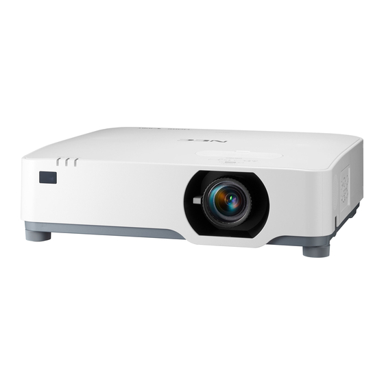
This section introduces you to your new projector and describes the features and controls. General • Liquid crystal type high brightness/high resolution projector Model name Brightness Resolution Aspect ratio WUXGA PE455UL 4,500 lm 16:10 (1920 × 1200 pixels) WXGA PE455WL 4,500 lm 16:10 (1280 × 800 pixels) - Page 22 1. Check the product overview, supplied items and part names Installation • 360° installation and portrait projection The projector can be installed at any angle from 0° to 360° in both the vertical and horizontal direction. When installing the projector in a tilted position, use brackets of sufficient strength. Portraits can also be projected with the projection screen tilted 90°.
- Page 23 The projector supports CRESTRON ROOMVIEW, allowing multiple devices connected in the network to be managed and controlled from a computer. • Compatible with the MultiPresenter application This projector is compatible with the NEC MultiPresenter application, so multi-screen projection is possible via the network (wired LAN/wireless LAN). Energy-saving • 0.11 W (100-130 V AC)/0.16 W (200-240 V AC) in standby condition with energy saving...
-
Page 24: What's In The Box
Batteries (AAA × 2) (7N901261) Power cord Computer cable (VGA) Lens cap strap (US: 7N080236/7N080242) (7N520089) (EU: 7N080022/7N080028) NEC Projector CD-ROM (7N952911) • Important Information (7N8N9901) • Quick Setup Guide (For North America: 7N8N9881) (For Other countries than North America: 7N8N9881 and 7N8N9891) • Security Sticker (Use this sticker when security password is set on.) For North America only • Limited warranty... -
Page 25: Part Names Of The Projector
1. Check the product overview, supplied items and part names 1-3. Part Names of the Projector Front 1. Lens shift cover 11. Security chain opening (→ page 23) Attach an anti-theft device. The security chain opening accepts security 2. Zoom Lever wires or chains up to 0.18 inch/4.6 mm in (→... - Page 26 1. Check the product overview, supplied items and part names Mounting the lens cap strap 1. Insert the tip of the strap into the lens cap mount hole and pass the knot through. Lens cap mount hole 2. Insert the knot into the strap mount hole (large) on the bottom of the projector, then press it into the narrow (small) hole.
- Page 27 1. Check the product overview, supplied items and part names Rear 1. Terminal Panel (→ page 9) 2. AC Input Connect the supplied power cord’s three- pin plug here, and plug the other end into an active wall outlet. (→ page 16) 3. Intake Vent 4. Remote Sensor (→...
- Page 28 1. Check the product overview, supplied items and part names Controls/Indicators 4 3 2 (POWER) Button (→ page 18, 33) 2. POWER Indicator (→ page 16, 18, 33, 146) 3. STATUS Indicator (→ page 146) 4. LIGHT Indicator (→ page 146) 5. INPUT Button (→...
- Page 29 1. Check the product overview, supplied items and part names Terminal Panel Features 1. HDMI 1 IN Terminal (Type A) 7. USB Port (Type A) Connect the USB memory. When picture data (→ page 84, 85, 87) is saved in a USB memory, the picture can be 2.
-
Page 30: Part Names Of The Remote Control
1. Check the product overview, supplied items and part names 1-4. Part Names of the Remote Control 1. Infrared Transmitter (→ page 14) 2. POWER ON Button (→ page 18) 3. POWER STANDBY Button (→ page 33) 4. SOURCE Button (→ page 20) 5. - Page 31 1. Check the product overview, supplied items and part names 12. USB-A Button (→ page 20, 96) 13. USB-B Button (This button does not work in this series of projectors) 14. APPS Button (→ page 20, 107) 15. ID SET Button (→ page 73) 16. Numeric Keypad Button/CLEAR Button (→...
- Page 32 1. Check the product overview, supplied items and part names 23. ENTER Button (→ page 48) 24. D-ZOOM (+)(−) Button (→ page 36) 25. MOUSE L-CLICK Button (This button does not work in this series of projectors) 26. MOUSE R-CLICK Button (This button does not work in this series of projectors) 27.
- Page 33 1. Check the product overview, supplied items and part names Battery Installation 1. Press firmly and slide the battery cover off. 2. Install new batteries (AAA). Ensure that you have the batteries’ polarity (+/−) aligned correctly. 3. Slip the cover back over the batteries until it snaps into place. Do not mix different types of batteries or new and old batteries.
- Page 34 1. Check the product overview, supplied items and part names Operating Range for Wireless Remote Control 30° 30° 30° 30° Remote control 23 feet/7 m 23 feet/7 m Remote sensor on projector cabinet 30° 30° 30° 30° • The infrared signal operates by line-of-sight up to a distance of about 23 feet/7 m and within a 60-degree angle of the remote sensor on the projector cabinet. • The projector will not respond if there are objects between the remote control and the sensor, or if strong light falls on the sensor.
-
Page 35: Projecting An Image (Basic Operation)
2. Projecting an Image (Basic Operation) This section describes how to turn on the projector and to project a picture onto the screen. 2-1. Flow of Projecting an Image Step 1 • Connecting your computer / Connecting the power cord (→ page 16) Step 2 • Turning on the projector (→ page 18) Step 3 • Selecting a source (→... -
Page 36: Connecting Your Computer/Connecting The Power Cord
2. Projecting an Image (Basic Operation) 2-2. Connecting Your Computer/Connecting the Power Cord 1. Connect your computer to the projector. This section will show you a basic connection to a computer. For information about other connections, see “5. Making Connections” on page 83. Connect the computer cable (VGA) between the projector’s COMPUTER IN terminal and the computer’s port (mini D-Sub 15 Pin). - Page 37 2. Projecting an Image (Basic Operation) CAUTION: Parts of the projector may become temporarily heated if the projector is turned off with the POWER button. Be careful to handle the projector.
-
Page 38: Turning On The Projector
2. Projecting an Image (Basic Operation) 2-3. Turning on the Projector WARNING The projector produces a strong light. When turning on the power, make sure no one within projection range is looking at the lens. 1. Remove the lens cap. With the lens cap’s stopper pressed up, pull forward and off. - Page 39 2. Projecting an Image (Basic Operation) Note on Startup screen (Menu Language Select screen) When you first turn on the projector, you will get the Startup menu. This menu gives you the op- portunity to select one of the 30 menu languages. To select a menu language, follow these steps: 1.
-
Page 40: Selecting A Source
2. Projecting an Image (Basic Operation) 2-4. Selecting a Source Selecting the computer or video source NOTE: • Turn on the computer or video source equipment connected to the projector. Detecting the Signal Automatically Press the INPUT button once. The projector will search for the available input source and display it. The input source will change as follows: [HDMI1] →... - Page 41 2. Projecting an Image (Basic Operation) Selecting Default Source You can so that it will be displayed each time the projector is turned on. 1. Press the MENU button. The menu will be displayed. 2. Press the ▶ button twice to select [SETUP] and the ▼ button or the ENTER button to select [GENERAL].
-
Page 42: Adjusting The Picture Size And Position
2. Projecting an Image (Basic Operation) 2-5. Adjusting the Picture Size and Position Use the lens shift dial, the adjustable tilt foot lever, the zoom lever/zoom ring and the focus ring to adjust the picture size and position. In this chapter drawings and cables are omitted for clarity. Adjusting the projected image’s vertical and Adjusting the focus [Focus ring] horizontal position [Lens shift]... - Page 43 2. Projecting an Image (Basic Operation) Adjusting the vertical position of a projected image (Lens shift) CAUTION Perform the adjustment from behind or from the side of the projector. Adjusting from the front could expose your eyes to strong light which could injure them. 1.
- Page 44 2. Projecting an Image (Basic Operation) NOTE: • The dials can be turned more than one full turn, but the projection position cannot be moved more than the range indicated on the following page. Do not force to turn the dials. Doing so may damage the dials. • If the lens is shifted to the maximum in the diagonal direction, the edges of the screen will be dark or shaded. • The vertical shift adjustment must be finished with an image shifted upward. If you finish the vertical shift adjustment with an image shifted down, the zoom/focus adjustments or strong shaking may cause a projected image to slightly shift down. 3. Close the lens shift cover. Insert the cover’s 2 (two) hooks into the grooves in the projector, then close the cover. Hook Groove TIP: • The diagram below shows the lens shift adjustment range ([ORIENTATION]: [DESKTOP FRONT]). • For the lens shift adjustment range regarding the [CEILING FRONT] projection, see page 128. 29%H 100%H 29%H...
- Page 45 2. Projecting an Image (Basic Operation) Focus Use the focus ring to obtain the best focus. Focus ring NOTE: • Recommend to perform the focus adjustment after leaving the projector under the state the TEST PATTERN has been projected for over 30 minutes. Please refer to page 73 about the TEST PATTERN.
- Page 46 2. Projecting an Image (Basic Operation) Zoom Turn the zoom lever clockwise and counterclockwise. Zoom lever...
- Page 47 2. Projecting an Image (Basic Operation) Adjusting the tilt (Tilt foot) Adjusting the left and right tilt. 1. Turn the left and right tilt feet to adjust. The tilt feet lengthen and shorten when turned. The height of the projected image is adjusted by turning the left and right tilt feet.
-
Page 48: Correcting Keystone Distortion [Keystone]
2. Projecting an Image (Basic Operation) 2-6. Correcting Keystone Distortion [KEYSTONE] When the projector is not exactly perpendicular to the screen, keystone distortion occurs. For cor- recting this distortion, you can use the “Keystone” function, a digital technology that can adjust for keystone-type distortion, resulting in a crisp, square image. - Page 49 2. Projecting an Image (Basic Operation) 5. Press the ▼ button to select [KEYSTONE Projected area VERTICAL] and then use the ◀ or ▶ so that Screen frame the left and right sides of the projected image are parallel. • Adjust the vertical keystone distortion. 6. Align the left (or right) side of the screen with the left (or right) side of the projected image.
- Page 50 2. Projecting an Image (Basic Operation) NOTE: • Even when the projector is turned on, the last used correction values are applied. • The KEYSTONE feature can cause an image to be slightly blurred because the correction is made electronically.
- Page 51 2. Projecting an Image (Basic Operation) To return the keystone adjustments to default: 1. Display the [GEOMETRIC CORRECTION] screen, and make sure [KEYSTONE] is selected at [MODE]. 2. Press the ▼ button to select [RESET] and press the ENTER button. 3. Press the ◀ or ▶ button to select [YES] and press the ENTER button. The adjustments will be reset. NOTE: • All adjusted values set in the [KEYSTONE] adjustment are reset to initial values.
-
Page 52: Optimizing Computer Signal Automatically
2. Projecting an Image (Basic Operation) 2-7. Optimizing Computer Signal Automatically Adjusting the Image Using Auto Adjust Optimizing a computer image automatically. (COMPUTER) Press the AUTO ADJ. button on the remote control to optimize a computer image automatically. This adjustment may be necessary when you connect your computer for the first time. -
Page 53: Turning Off The Projector
2. Projecting an Image (Basic Operation) 2-9. Turning off the Projector To turn off the projector: 1. First, press the (POWER) button on the projector cabinet or the STANDBY button on the remote control. The confirmation message will be displayed. •... -
Page 54: When Moving The Projector
2. Projecting an Image (Basic Operation) CAUTION: Parts of the projector may become temporarily heated if the projector is turned off with the POWER button. Be careful to handle the projector. NOTE: • While the POWER indicator is blinking blue in short cycles, the power cannot be turned off. • Do not unplug the power cord from the projector or from the power outlet while an image is being projected. Doing so could deteriorate the projector’s AC IN terminal or the power plug’s contact. To turn off the AC power while an image is being projected, use the power strip’s switch, the breaker, etc. • Do not disconnect the AC power supply to the projector within 10 seconds of making adjustment or setting changes and closing the menu. Doing so can cause loss of adjustments and settings. -
Page 55: Convenient Features
3. Convenient Features 3-1. Turning off the Image and Sound Press the AV-MUTE button to turn off the image and sound for a short period of time. Press again to restore the image and sound. NOTE: • Even though the image is turned off, the menu still remains on the screen. 3-2. Freezing a Picture Press the FREEZE button. -
Page 56: Magnifying A Picture
3. Convenient Features 3-3. Magnifying a Picture You can enlarge the picture up to four times. NOTE: • The maximum magnification may be less than four times depending on the signal. To do so: 1. Press the D-ZOOM (+) button to magnify the picture. To move the magnified image, use the ▲,▼,◀ or ▶ button. 2. Press the ▲▼◀▶ button. The area of the magnified image will be moved. -
Page 57: Changing Eco Mode/Checking Energy-Saving Effect
3. Convenient Features 3-4. Changing Eco Mode/Checking Energy-Saving Effect Using Eco Mode [ECO MODE] Two eco modes can be selected according to the purpose of use for the projector. [ECO MODE] Icon at the bottom of Description Status of LIGHT indicator the menu [OFF] 100% brightness Steady green The screen will be brightly lit. light [ECO] Brightness will be at about 60% (PE455WL: 67%). - Page 58 3. Convenient Features Checking Energy-Saving Effect [CARBON METER] This feature will show energy-saving effect in terms of CO emission reduction (kg) when the projec- tor’s [ECO MODE] is set to [ECO] or [LONG LIFE]. This feature is called as [CARBON METER]. There are two messages: [TOTAL CARBON SAVINGS] and [CARBON SAVINGS-SESSION].
-
Page 59: Correcting Distortion Of Projected Image
3. Convenient Features 3-5. Correcting distortion of projected image Use the [CORNERSTONE] and [PINCUSHION] features to correct keystone (trapezoidal) distortion to make the top or bottom and the left or right side of the screen longer or shorter so that the projected image is rectangular. - Page 60 3. Convenient Features 5. Press the ▼ button to select [CORNER- STONE] and press the ENTER button. The [CORNERSTONE] screen will be displayed. The drawing shows the upper left icon ( ) is selected. 6. Project an image so that the screen is Projected image smaller than the area of the raster.
- Page 61 3. Convenient Features 13. Press the ◀ or ▶ button to highlight the [OK] and press the ENTER button. This completes the Cornerstone correction. • Selecting [CANCEL] will return to the ad- justment screen without saving changes (Step 3). • Selecting [RESET] will return to the factory default. • Selecting [UNDO] will exit without saving changes. 14. Press the EXIT button a few times to turn off the menu.
- Page 62 3. Convenient Features Pincushion By this feature, it enables to adjust left and right side or top and bottom side independently for reforming pincushion distortion. 1. Press the ▼ button with no menu displayed. The [GEOMETRIC CORRECTION] screen will be displayed. •...
- Page 63 3. Convenient Features 6. Press the ◀ or ▶ button to correct distor- tion. NOTE: • The [PINCUSHION LEFT/RIGHT] or [PINCUSHION TOP/BOT- TOM] item is not available when [KEYSTONE HORIZONTAL], [KEYSTONE VERTICAL] or [CORNERSTONE] is activated. • Before performing correction, set the lens shift to the center position. 7. After completing [PINCUSHION] adjust- ment, press the EXIT button a few times to turn off the menu. NOTE: • Even when the projector is turned on, the last used correction values are applied.
- Page 64 3. Convenient Features Reset the keystone and pincushion adjustment to the default value 1. Display the [GEOMETRIC CORRECTION] screen, and make sure [KEYSTONE] is selected at [MODE]. 2. Press the ▼ button to select [RESET] and press the ENTER button. • Confirmation message is displayed on. 3. Move the cursor onto [YES] using either ◀ or ▶ button and then press the ENTER. NOTE: • All adjusted values set in the [KEYSTONE] adjustment are reset to initial values. TIP: • Distortion when projecting on specially shaped surfaces (cylindrical or spherical surfaces, for example) can be corrected using our Geometric Correction Tool application. Please download Geometric Correction Tool from our web site. https://www.nec-display.com/dl/en/index.html...
-
Page 65: Preventing The Unauthorized Use Of The Projector [Security]
3. Convenient Features 3-6. Preventing the Unauthorized Use of the Projector [SECURITY] A keyword can be set for your projector using the Menu to avoid operation by an unauthorized user. When a keyword is set, turning on the projector will display the Keyword input screen. Unless the correct keyword is entered, the projector cannot project an image. - Page 66 3. Convenient Features 7. Type in the same combination of ▲▼◀▶ buttons and press the ENTER button. The confirmation screen will be displayed. 8. Select [YES] and press the ENTER button. The [SECURITY] function has been enabled. To turn on the projector when [SECURITY] is enabled: 1. Press the POWER button. The projector will be turned on and display a message to the effect that the projector is locked. 2.
- Page 67 3. Convenient Features To disable the [SECURITY] function: 1. Press the MENU button. The menu will be displayed. 2. Select [SETUP] → [INSTALLATION] → [SECURITY] and press the ENTER button. The [OFF/ON] menu will be displayed. 3. Select [OFF] and press the ENTER button. The [SECURITY KEYWORD] screen will be displayed. 4. Type in your keyword and press the ENTER button. When the correct keyword is entered, the [SECURITY] function will be disabled. NOTE: • If you forget your keyword, contact your dealer. Your dealer will provide you with your keyword in exchange for your request code.
-
Page 68: Using On-Screen Menu
4. Using On-Screen Menu 4-1. Using the Menus NOTE: • The on-screen menu may not be displayed correctly while interlaced motion video image is projected. 1. Press the MENU button on the remote control or the projector cabinet to display the menu. NOTE: • The commands such as ENTER, EXIT, ▲▼, ◀▶ in the bottom show available buttons for your operation. 2. Press the ◀▶ buttons on the remote control or the projector cabinet to display the submenu. - Page 69 4. Using On-Screen Menu Menu Elements Slide bar Solid triangle Available buttons Source Highlight Radio button Wireless symbol Menu mode ECO mode symbol Off Timer remaining time Thermometer symbol Key Lock symbol Menu windows or dialog boxes typically have the following elements: Highlight Indicates the selected menu or item.
-
Page 70: List Of Menu Items
COLOR TEMPERATURE DYNAMIC CONTRAST OFF, ON IMAGE MODE STILL, MOVIE COLOR ENHANCEMENT OFF, LOW, MEDIUM, HIGH WHITE CONTRAST R BALANCE CONTRAST G CONTRAST B BRIGHTNESS R BRIGHTNESS G BRIGHTNESS B CONTRAST BRIGHTNESS SHARPNESS COLOR RESET IMAGE OPTIONS CLOCK PHASE HORIZONTAL VERTICAL OVERSCAN AUTO, 0[%], 5[%], 10[%] ASPECT RATIO AUTO, 4:3, 16:9, 15:9, 16:10, LETTERBOX, NATIVE POSITION* AUDIO VOLUME * This function is not available for PE455UL/PE455WL. - Page 71 4. Using On-Screen Menu Menu Item Options SETUP GENERAL WALL COLOR (B) OFF, WHITEBOARD, BLACKBOARD, BLACKBOARD (GRAY), LIGHT YELLOW, LIGHT GREEN, LIGHT BLUE, SKY BLUE, LIGHT ROSE, PINK LIGHT MODE (B) ECO MODE OFF, ECO, LONG LIFE ADJUST CONSTANT BRIGHTNESS OFF, ON OFF TIMER (B) OFF, 0:30, 1:00, 2:00, 4:00, 8:00, 12:00, 16:00 DATE AND TIME SETTINGS ADMINISTRATOR MODE (B) MENU MODE ADVANCED, BASIC NOT SAVE SETTING VALUES OFF, ON KEYWORD OFF, ON LANGUAGE (B) ENGLISH, DEUTSCH, FRANÇAIS, ITALIANO, ESPAÑOL, SVENSKA, 日本語 DANSK, PORTUGUÊS, ČEŠTINA, MAGYAR, POLSKI, NEDERLANDS, SUOMI NORSK, TÜRKÇE, РУССКИЙ, , ΕΛΛΗΝΙΚΆ, 简体中文, 한국어, TIẾNG ViỆT ROMÂNĂ, HRVATSKI, БЪЛГАРСКИ, INDONESIA, हिन्...
- Page 72 4. Using On-Screen Menu Menu Item Options SETUP OPTIONS(1) SEAMLESS SWITCHING OFF, ON FAN MODE AUTO, HIGH ALTITUDE SIGNAL SELECT COMPUTER RGB/COMPONENT, RGB, COMPONENT WXGA MODE OFF, ON DEINTERLACE OFF, ON VIDEO LEVEL HDMI1 AUTO, NORMAL, ENHANCED HDMI2 AUTO, NORMAL, ENHANCED AUDIO SELECT HDMI1 HDMI1, COMPUTER HDMI2 HDMI2, COMPUTER LAN, COMPUTER BEEP OFF, ON OPTIONS(2) STANDBY MODE NORMAL, NETWORK STANDBY, SLEEP DIRECT POWER ON OFF, ON AUTO POWER ON OFF, AUTO, HDMI1, HDMI2, COMPUTER AUTO POWER OFF OFF, 0:05, 0:10, 0:15, 0:20, 0:30, 1:00 DEFAULT INPUT SELECT LAST, AUTO, HDMI1, HDMI2, COMPUTER, USB-A, LAN...
- Page 73 4. Using On-Screen Menu Menu Item Options INFO. WIRELESS LAN IP ADDRESS SUBNET MASK GATEWAY MAC ADDRESS SSID NETWORK TYPE SECURITY CHANNEL SIGNAL LEVEL VERSION(1) (B) FIRMWARE DATA VERSION(2) (B) FIRMWARE2 DATA2 OTHERS (B) DATE TIME PROJECTOR NAME HOST NAME MODEL NO. SERIAL NUMBER LAN UNIT TYPE CONTROL ID (when [CONTROL ID] is set) CONDITIONS INTAKE TEMPERATURE EXHAUST TEMPERATURE INSTALLATION POSITION X-AXIS Y-AXIS Z-AXIS RESET CURRENT SIGNAL...
-
Page 74: Menu Descriptions & Functions [Input]
4. Using On-Screen Menu 4-3. Menu Descriptions & Functions [INPUT] [HDMI1] and [HDMI2] Selects the HDMI compatible equipment connected to your HDMI 1 IN or HDMI 2 IN terminal. [COMPUTER] Selects the computer connected to your COMPUTER IN terminal signal. NOTE: • When the component input signal is connected to the COMPUTER IN terminal, select [COMPUTER]. -
Page 75: Menu Descriptions & Functions [Adjust]
4. Using On-Screen Menu 4-4. Menu Descriptions & Functions [ADJUST] [PICTURE] [PRESET] This function allows you to select optimized settings for your projected image. You can adjust neutral tint for yellow, cyan or magenta. There are seven factory presets optimized for various types of images. You can also use [DETAIL SETTINGS] to set user adjustable settings to customize each gamma or color. - Page 76 4. Using On-Screen Menu [DETAIL SETTINGS] This function allows you to store your customized settings in [PRESET 1] to [PRESET 7]. First, select a base preset mode from [REFERENCE], then set [GAMMA CORRECTION], [SCREEN SIZE], [COLOR TEMPERATURE], [DYNAMIC CONTRAST], [IMAGE MODE], and [COLOR ENHANCEMENT]. Storing Your Customized Settings [REFERENCE] Select a mode to serve as the basis for the [DETAIL SETTINGS].
- Page 77 4. Using On-Screen Menu Adjusting Color Temperature [COLOR TEMPERATURE] Adjust the balance of the colors (R, G, B) to optimize the color reproducibility. A color temperature with a high numerical value becomes bluish white while one with a low nu- merical value becomes reddish white. A value between 5000 K and 10500 K can be set in 100 K units.
- Page 78 4. Using On-Screen Menu [CONTRAST] Adjusts the intensity of the image according to the incoming signal. [BRIGHTNESS] Adjusts the brightness level or the back raster intensity. [SHARPNESS] Controls the detail of the image. [COLOR] Increases or decreases the color saturation level. [HUE] Varies the color level from +/−...
- Page 79 4. Using On-Screen Menu [IMAGE OPTIONS] Adjusting Clock and Phase [CLOCK/PHASE] This allows you to manually adjust [CLOCK] and [PHASE]. CLOCK Use this item to fine tune the computer image or to remove any vertical banding that might appear. This function adjusts the clock frequencies that eliminate the horizontal banding in the image. This adjustment may be necessary when you connect your computer for the first time. PHASE Use this item to adjust the clock phase or to reduce video noise, dot interference or cross talk. (This is evident when part of your image appears to be shimmering.) Use [PHASE] only after the [CLOCK] is complete.
- Page 80 4. Using On-Screen Menu Adjusting Horizontal/Vertical Position [HORIZONTAL/VERTICAL] Adjusts the image location horizontally and vertically. NOTE: • [CLOCK], [PHASE], [HORIZONTAL] and [VERTICAL] can only be selected when inputting analog signals. • An image can be distorted during the adjustment of [CLOCK] and [PHASE]. This is not malfunction. • The adjustments for [CLOCK], [PHASE], [HORIZONTAL], and [VERTICAL] will be stored in memory for the current signal. T he next time you project the signal with the same resolution, horizontal and vertical frequency, its adjustments will be called up and applied. To delete adjustments stored in memory, from the menu, you select [RESET] → [CURRENT SIGNAL] or [ALL DATA] and reset the adjustments. Selecting Overscan Percentage [OVERSCAN] This allows you to set the appropriate overscan for an incoming signal. When [AUTO] is selected, the over-scan that is most suitable for the input signal is carried out and displayed.
- Page 81 The image is displayed in 4:3 aspect ratio. 16:9 The image is displayed in 16:9 aspect ratio. 15:9 The image is displayed in 15:9 aspect ratio. 16:10 The image is displayed in 16:10 aspect ratio. LETTERBOX The image of a letterbox signal is stretched equally in the horizontal and vertical directions to fit the screen. Parts of the displayed image are cropped at the top and bottom edges and therefore not visible. NATIVE The projector displays the current image in its true resolution when the incoming computer signal has a lower resolution than the projector’s native resolution. [Example 1] When the incoming signal with the resolution of 800 × 600 is displayed on the PE455UL/PE455WL: [Example 2] When the incoming signal with the resolution of 800 × 600 is displayed on the PE505XL: NOTE: • When a non-computer signal is displayed, the [NATIVE] is not available. • When a signal with a higher resolution than the projector’s native resolution is displayed, [NATIVE] is not available. TIP: • This table shows typical resolutions and aspect ratios that most computers support. Resolution Aspect Ratio 640 × 480 SVGA 800 × 600 1024 ×...
- Page 82 4. Using On-Screen Menu Adjusting the Vertical Position of Image [POSITION] (not available on PE455UL/ PE455WL) (only when [16:9], [15:9], or [16:10] is selected for [ASPECT RATIO]) When [16:9], [15:9], or [16:10] is selected in [ASPECT RATIO], the image is displayed with black borders on the top and bottom. You can adjust the vertical position from the top to the bottom of the black area.
-
Page 83: Menu Descriptions & Functions [Setup]
4. Using On-Screen Menu 4-5. Menu Descriptions & Functions [SETUP] [GENERAL] Using the Wall Color Correction [WALL COLOR] This function allows for quick adaptive color correction in applications where the screen material is not white. NOTE: • Selecting [WHITEBOARD] reduces brightness. - Page 84 4. Using On-Screen Menu Eco mode selection and brightness adjustment [LIGHT MODE] Adjusting the energy savings settings and the brightness of each projector in multi-screen projection. For energy savings settings, see page “3-4 Changing Eco Mode/Checking Energy-Saving Effect”. ECO MODE The light module luminance (brightness) will be at the setup brightness for [ADJUST]. By controlling the brightness and fan speed, energy can be saved and motion noise and the power consumption can be lowered. LONG LIFE The mode optimizes the service life of the light module. ADJUST Brightness can be adjusted in 1% increments from 30 to 100% (PE455WL: 33 to 100%). When several projectors are used for multi-screen projection, the brightness can be adjusted individually on each projector.
- Page 85 4. Using On-Screen Menu Using Off Timer [OFF TIMER] 1. Select your desired time between 30 minutes and 16 hours: OFF, 0:30, 1:00, 2:00, 4:00, 8:00, 12:00, 16:00. 2. Press the ENTER button on the remote control. 3. The remaining time starts counting down. 4. The projector will turn off after the countdown is complete. NOTE: • To cancel the preset time, set [OFF] for the preset time or turn off the power. • When the remaining time reaches 3 minutes before the projector is turned off, the [THE PROJECTOR WILL TURN OFF WITHIN 3 MINUTES.] message will be displayed on the bottom of the screen. Setting the date and time [DATE AND TIME SETTINGS] Display the start-up screen of MultiPresenter (→ page 150) Configuring the menu settings [ADMINISTRATOR MODE] This allows you to select [MENU MODE], save settings, and set a [KEYWORD] for the [ADMINISTRA- TOR MODE].
- Page 86 4. Using On-Screen Menu [GEOMETRIC CORRECTION] [MODE] Set pattern for correcting distortion. If [OFF] is selected, the [GEOMETRIC CORRECTION] becomes ineffective. Correcting Keystone Distortion Manually [KEYSTONE] You can correct horizontal or vertical keystone, pincushion LEFT/RIGHT or TOP/BOTTOM, or corner- stone distortion manually. NOTE: • [KEYSTONE HORIZONTAL] and [KEYSTONE VERTICAL] can be adjusted at once. • To change from one item to another item, reset the first item.
- Page 87 4. Using On-Screen Menu PINCUSHION TOP/BOTTOM Corrects pincushion distortion at the top or bottom side. (→ page 42) CORNERSTONE Fits a projected image within the border of the screen easily by align the four corner of an image to the ones of the screen. (→ page 39) TIP: • Adjustable range of the [KEYSTONE] and the [CORNERSTONE]: Horizontal Direction Vertical Direction Approx. ±30° (Max) Approx. ±30° (Max) Adjustable range may be narrower depending on input signal. [PC TOOL] Recall the geometric correction data that is registered in the projector beforehand. The geometric correction data using our Geometric Correction Tool application (→ page 44) is registered here.
- Page 88 4. Using On-Screen Menu [MENU] Selecting Menu Color [COLOR SELECT] You can choose between two options for menu color: [COLOR] and [MONOCHROME]. Turning On / Off Input Display [INPUT DISPLAY] This option turns on or off input name display such as [COMPUTER] to be displayed on the top right of the screen. When no input signal is present, the no-signal guidance prompting you to check for an available input will be displayed at the center of the screen.
- Page 89 4. Using On-Screen Menu Selecting a Color or Logo for Background [BACKGROUND] When the HDMI1, HDMI2, or COMPUTER input terminal is selected, select the desired background when there is no input signal. BLUE The background color is blue BLACK The background color is black LOGO Display an image as the background NOTE: • When [INPUT DISPLAY] is turned on, the no-signal guidance prompting you to check for an available input will be displayed at the center of the screen regardless of its selection. • To change the background image to be displayed as a [LOGO], see page 104. • Your setting will not be affected even when [RESET] is done from the menu.
- Page 90 4. Using On-Screen Menu [INSTALLATION] Selecting Projector Orientation [ORIENTATION] This reorients your image for your type of projection. The options are: desktop front projection, ceiling rear projection, desktop rear projection, and ceiling front projection. WARNING • Should special works be required, for example to suspend the projector from the ceiling, consult your dealer.
- Page 91 4. Using On-Screen Menu CEILING FRONT Disabling the Cabinet Buttons [CONTROL PANEL LOCK] This option turns on or off the [CONTROL PANEL LOCK] function. NOTE: • This [CONTROL PANEL LOCK] does not affect the remote control functions. • How to release the [CONTROL PANEL LOCK] 1. When the projector is projecting image or in the sleep mode, press and hold the INPUT button on the projector cabinet for about 10 seconds. The [CONTROL PANEL LOCK] will be released. 2. When the projector is in the standby mode, press and hold the POWER button on the projector cabinet. It enables to power on the projector. After checking the projector is projecting image, perform the previous step 1. TIP: • When the [CONTROL PANEL LOCK] is turned on, a key lock icon [ ] will be displayed at the bottom right of the menu. Enabling Security [SECURITY] This feature turns on or off the [SECURITY] function. Unless the correct keyword is entered, the projector cannot project an image.
- Page 92 4. Using On-Screen Menu Turning On or Off Remote Sensor [REMOTE SENSOR] Set the remote control sensors on the projector’s front and rear panels. The options are: [FRONT/BACK], [FRONT], and [BACK]. TIP: • If the remote control system does not function when direct sunlight or strong illumination strikes the remote control sensor of the projector, change another option. • The remote control sensor on the back of the projector cannot be used when the separately sold cable cover is mounted on the projector. Setting ID to the Projector [CONTROL ID] You can operate multiple projectors separately and independently with the single remote control that has the [CONTROL ID] function.
- Page 93 4. Using On-Screen Menu Assigning or Changing the Control ID 1. Turn on the projector. 2. Press the ID SET button on the remote control. The [CONTROL ID] screen will be displayed. If the projector can be operated with the current remote control ID, the [CONTROL ID (ACTIVE)] will be displayed.
- Page 94 4. Using On-Screen Menu [OPTIONS(1)] Switching the displayed image smoothly [SEAMLESS SWITCHING] When the input connector is switched, the image displayed before switching is held to switch to the new image without a break due to absence of a signal. Selecting Fan Mode [FAN MODE] [FAN MODE] is used to set the speed of the internal cooling fan. AUTO The built-in fans automatically run at a variable speed according to the internal temperature.
- Page 95 4. Using On-Screen Menu Enabling the deinterlace [DEINTERLACE] Turns on or off the deinterlace function for a telecine signal. Select this option if there is any jitter or artifacts in video. Default standard setting. NOTE: • This function is not available for HDTV (progressive) and computer signals. Setting HDMI1 or HDMI2 [VIDEO LEVEL] Make the settings for each video level when connecting HDMI equipment. Select [AUTO] to automatically detect video level. If automatic detection may not work well, select [NORMAL] to disable the [ENHANCED] feature of your HDMI equipment or select [ENHANCED] to improve image contrast and increase detail in the dark areas.
- Page 96 4. Using On-Screen Menu [OPTIONS(2)] Selecting Power-saving in [STANDBY MODE] Set the mode after turning off the power of the projector. NORMAL The projector will go into the standby mode, lowering the power con- Power consumption: sumption. The POWER indicator flashes in orange. When [NORMAL] is selected, only the following buttons and feature will work: POWER button on the projector cabinet and the remote control, powering on from PC Control command, and [AUTO POWER ON]. NETWORK STANDBY The projector goes into the network standby mode. The power supply of Power consumption: the projector can be turned on using a wired LAN (LAN port). Medium The POWER indicator lights up in orange. When [NETWORK STANDBY] is selected, only the following buttons, terminals, and features will work: POWER button on the projector cabinet and the remote control, powering on from PC Control command, [AUTO POWER ON], [NETWORK SERVICE]. SLEEP The projector is maintained in the sleep mode. Power consumption: POWER indicator lights up in green. High...
- Page 97 4. Using On-Screen Menu Important: • When [NETWORK STANDBY] has been set for [STANDBY MODE] and the LAN has been in link-down condition for 3 minutes, [STANDBY MODE] will transit into [NORMAL] automatically for the purpose to save the consumption power. • When [NETWORK STANDBY] is selected, [AUTO POWER OFF] will turn in grey and be disabled and [0:15] will be selected automati- cally for [AUTO POWER OFF]. • In the below conditions, setting of the [STANDBY MODE] is disabled and the projector will go into the SLEEP mode*. * Sleep mode refers the mode without functional restrictions by the [STANDBY MODE]. When [STANDBY MODE] → [NETWORK STANDBY] is selected - When [NETWORK SERVICE] → [AMX BEACON] → [ON] is selected - When [NETWORK SERVICE] → [CRESTRON] → [Crestron Control] → [ON] is selected - When [NETWORK SETTINGS] → [WIRELESS LAN] → Except for [DISABLE] and mounting the wireless LAN unit to the projector - When the signal is input to the computer, HDMI 1 IN or HDMI 2 IN terminals TIP: • Even when [NORMAL] is selected for [STANDBY MODE], power on or off can be done by using the PC CONTROL port. However, in the [NORMAL] mode, ASCII CONTROL COMMAND cannot be used. W hen using ASCII CONTROL COMMAND, set it to [NETWORK STANDBY] or [SLEEP]. • The power consumption in the standby mode will not be included in calculating CO emission reduction. • Your setting will not be affected even when [RESET] is done from the menu. Enabling Direct Power On [DIRECT POWER ON] Turns the projector on automatically when the power cord is inserted into an active power outlet. This eliminates the need to always use the POWER button on the remote control or projector cabinet.
- Page 98 4. Using On-Screen Menu NOTE: • This function will not be available under the following conditions: - when a component signal is applied to the COMPUTER IN terminal - when a Sync on Green RGB signal or composite sync signal is applied • To enable the [AUTO POWER ON] after changing to the sleep mode turning off the projector, wait 30 seconds and input a computer or HDMI signal. If a computer or HDMI signal is still present when the projector is turned off, the [AUTO POWER ON] will not work and the projector remains in standby mode. • Depending on the projector in use, the [AUTO POWER ON] may not work properly. In this case, set [STANDBY MODE] to [NETWORK STANDBY]. Enabling Power Management [AUTO POWER OFF] When this option is selected you can enable the projector to automatically turn off (at the selected time: 0:05, 0:10, 0:15, 0:20, 0:30, 1:00) if there is no signal received by any input or if no operation is performed.
- Page 99 4. Using On-Screen Menu Changing currency setting and currency convert setting [CURRENCY CONVERT] Changes currency setting and currency convert setting for CARBON METER. The initial setting are as follows: US Dollar 0.11 [$/kWh] EU Euro 0.19 [€/kWh] Japanese Yen 20 [¥/kWh] Chinese Yuan 0.48 [¥/kWh] The initial settings for US dollar, EU Euro, and Japanese Yen are based on “Energy Prices and Taxes (second quarter 2010)”...
-
Page 100: Menu Descriptions & Functions [Info.]
4. Using On-Screen Menu 4-6. Menu Descriptions & Functions [INFO.] Displays the status of the current signal and light module usage. This item has nine pages. The information included is as follows: TIP: • Pressing the HELP button on the remote control will show the [INFO.] menu items. [USAGE TIME] [LIGHT HOURS USED] (H) [TOTAL CARBON SAVINGS] (kg-CO2) [TOTAL COST SAVINGS] •... - Page 101 4. Using On-Screen Menu [VERSION(1)] [FIRMWARE] Version [DATA] Version [VERSION(2)] [FIRMWARE2] Version [DATA2] Version [OTHERS] [DATE TIME] [PROJECTOR NAME] [HOST NAME] [MODEL NO.] [SERIAL NUMBER] [LAN UNIT TYPE] [CONTROL ID] (when [CONTROL ID] is set) [CONDITIONS] [INTAKE TEMPERATURE] [EXHAUST TEMPERATURE] [INSTALLATION POSITION] [X-AXIS] [Y-AXIS]...
-
Page 102: Menu Descriptions & Functions [Reset]
4. Using On-Screen Menu 4-7. Menu Descriptions & Functions [RESET] Returning to Factory Default [RESET] The [RESET] feature allows you to change adjustments and settings to the factory preset for a (all) source(s) except the following: [CURRENT SIGNAL] Resets the adjustments for the current signal to the factory preset levels. The items that can be reset are: [PRESET], [CONTRAST], [BRIGHTNESS], [COLOR], [HUE], [SHARPNESS], [ASPECT RATIO], [HORIZONTAL], [VERTICAL], [CLOCK], [PHASE], and [OVERSCAN]. -
Page 103: Making Connections
Computer cables and HDMI can be used to connect to a computer. The HDMI cable is not enclosed with the projector. Please get ready a suitable cable for the connection. NOTE: • Signals supported by Plug & Play (DDC2) INPUT COMPUTER IN HDMI 1 IN HDMI 2 IN analog digital digital NOTE: • The projector is not compatible with video decoded outputs of the NEC ISS-6020 switcher. • An image may not be displayed correctly when a Video source is played back via a commercially available scan converter. This is because the projector will process a video signal as a computer signal at the default setting. In that case, do the following. * When an image is displayed with the lower and upper black portion of the screen or a dark image is not displayed correctly: Project an image to fill the screen and then press the AUTO ADJ. button on the remote control. - Page 104 5. Making Connections HDMI cable (not supplied) Use High Speed HDMI® Cable. HDMI 1 IN HDMI 2 IN COMPUTER IN AUDIO IN Stereo mini-plug audio cable (not supplied) Computer cable (VGA) (supplied) To mini D-Sub 15-pin terminal on the projector. It is recommended that you use a commercially available distribution amplifier if connecting a signal cable longer than the cable supplied.
- Page 105 5. Making Connections Cautions when using a DVI signal • When the computer has a DVI output terminal, use a commercially available converter cable to connect the computer to the projector’s HDMI 1 IN or HDMI 2 IN terminal (only digital video signals can be input). - Only digital video signals can be input. HDMI 1 IN HDMI 2 IN AUDIO IN...
-
Page 106: Connecting To A Dvd Player And Other Av Devices
5. Making Connections 5-2. Connecting to a DVD player and other AV devices Connecting Component Input Connection for component signal. Signal from the color difference signal output terminal on DVD players (DVD video output) and the YPbPr output terminal on the Hi-vision video can be projected. Recommend to connect the terminal for audio output on the DVD player to the audio components. - Page 107 5. Making Connections Connecting HDMI Input You can connect the HDMI output of your DVD player, hard disk player, Blu-ray player, or notebook type PC to the HDMI IN terminal of your projector. HDMI 1 IN HDMI 2 IN HDMI cable (not supplied) Use High Speed HDMI® Cable.
-
Page 108: Connecting To A Wired Lan
5. Making Connections 5-3. Connecting to a Wired LAN When the projector is connected to a wired LAN, you can use the web browser on a computer to control the projector using the HTTP server function. For more information, see “7. Connecting to a Network” (→ page 106). Example of LAN connection Example of wired LAN connection Server... -
Page 109: Connecting To A Wireless Lan (Optional: Np05Lm Series)
5. Making Connections 5-4. Connecting to a Wireless LAN (Optional: NP05LM series) The USB Wireless LAN Unit also provides a wireless LAN connection. To use a wireless LAN connec- tion, you are required to assign an IP address to the projector. For more information, see “7. - Page 110 5. Making Connections Attaching the USB Wireless LAN Unit NOTE: • The USB Wireless LAN Unit must be inserted into the USB Wireless LAN Unit port in the correct direction. It cannot be inserted in the reverse direction. If the USB Wireless LAN Unit is inserted in the reverse direction with excessive force applied, the USB port may break. • Before touching the USB W ireless LAN Unit, touch a metallic object (such as a door knob or aluminum window frame) to discharge the static electricity from your body. • Always insert or remove the USB W ireless LAN unit when the main power is turned off. Failure to do so may cause projector malfunc- tion or damage to the USB wireless LAN unit. If the projector will not work correctly, turn off the projector, disconnect the power cord, and then connect it again. • Do not insert other USB devices into the USB (wireless LAN) port in the wireless LAN cover. Do not insert the USB Wireless LAN unit into the USB port. NOTE: • When the cable cover is attached, remove it before inserting the USB Wireless LAN Unit. 1. Press the POWER button to turn off the pro- jector and set it into standby condition, and disconnect the power cord.
- Page 111 5. Making Connections 3. Insert the wireless LAN unit into the USB (wireless LAN) port with the side containing the indicator facing up. • Slowly slide the wireless LAN unit left and right, up and down, checking the insertion slot as you push the unit in. NOTE: • Do not force to insert the USB Wireless LAN Unit.
-
Page 112: Portrait Projection (Vertical Orientation)
5. Making Connections 5-5. Portrait projection (vertical orientation) Portrait screens from a computer can be projected by installing the projector in a vertical orientation. Precautions during installation • Please do not install the projector in a vertical orientation on top of the floor or table on its own. The intake vent or the exhaust vent may be obstructed, resulting in the projector get- ting warm and the possibility of fire and malfunction occurring. - Page 113 5. Making Connections Design and manufacturing conditions for the stand Please engage an installation service provider for the design and manufacture of the customized stand to be used for portrait projection. Please ensure that the following are complied with when designing the stand.
- Page 114 5. Making Connections Reference drawings * The drawing showing the dimensional requirements is not an actual stand design drawing. (Unit: mm) Screw holes for 4 - M4 use Notch Intake vent Exhaust Vent [Front View] [Side View] Horizontal adjuster Installation facing the exhaust vent downward, maintain a distance of at least 200 mm between the projector Exhaust vent and the floor.
-
Page 115: Using The Viewer
6. Using the VIEWER 6-1. Things you can do with the VIEWER The [VIEWER] has the following features. • When you insert a commercially available USB memory containing the picture into the USB port of the projector (Type A), the images on the USB can be projected by the unit. By doing this, you can make a presentation without using a personal computer. -
Page 116: Projecting The Pictures On A Usb Memory (Basic Operation)
6. Using the VIEWER 6-2. Projecting the pictures on a USB memory (basic operation) This section explains the basic operations of the [VIEWER]. This is the operating procedure when the option menu (→ page 103) of the [VIEWER] is in the default state when shipped from the factory. ①... - Page 117 6. Using the VIEWER 6. Move the cursor to the folder or image file with the ▲▼◀▶ buttons and press the ENTER button. • When a folder is selected, the file list screen for the folder is displayed. • If an image file is selected, the slide screen will be displayed. 7. Move the cursor to the image file in the file list screen, then press the ENTER button.
- Page 118 6. Using the VIEWER 11. Press the ▶ button to move the cursor to then press the ENTER button. The picture will rotate clockwise by 90°. • Every time you press the ENTER button in this state, the picture rotates 90° clockwise. 12. Press the ▶ button to move the cursor to then press the ENTER button.
- Page 119 6. Using the VIEWER 5. Remove the USB memory from the projector. NOTE: • If you remove a USB memory from the projector without executing [REMOVE USB DEVICE] in the menu, the operation of the unit may become unstable. In that case, turn off the power of the unit once and unplug the power cord from the outlet. Subsequently, wait for about 3 minutes before connecting the power cord to the socket and turning on the power of the unit. ③ End the [VIEWER] 1. Press the MENU button in the slide screen or file list screen. A control bar or a pop-up menu will be dis- played.
-
Page 120: Slide Screen Operations
6. Using the VIEWER 6-3. Slide screen operations The following operations can be performed on the slide screen. Button name Description ▶, PAGE ▽ Project the next picture. ◀, PAGE △ Project the previous picture. Display the pointer (→). The pointer moves when you press the ▼▲◀▶ button. If ENTER you press the ENTER button again, the pointer disappears. -
Page 121: File List Screen Operations
6. Using the VIEWER 6-4. File list screen operations How to view the file list screen ② ① ③ ④ ⑤ Display name Description Display the path of the projected folder. ① Path When a USB memory is inserted, the drive name is displayed as [USB]. Return to the folder at the upper (parent) level. - Page 122 6. Using the VIEWER File list screen operations Button name Description ▼▲◀▶ Move the cursor. ENTER • If the cursor is on a picture, the display switches to the slide screen. • If the cursor is on a folder, the files in the folder are displayed. • If the cursor is on [UP DIRECTORY], the display returns to the folder in the upper (parent) level. EXIT Return to the folder at the upper (parent) level. MENU Display the following pop-up menu. PAGE ▽...
-
Page 123: Option Menu
6. Using the VIEWER 6-5. Option menu When shipped from the Menu item Description factory PLAY MODE Select the display mode of the slide screen. MANUAL MANUAL: Switch the picture manually. AUTOMATIC: Switch the picture automatically according to the interval setting. INTERVAL Set the display interval when playing a slideshow auto- 5 (seconds) -
Page 124: Changing The Logo Data (Background Image)
Format JPEG or PNG pictures that can be displayed with the [VIEWER] Resolution Below the panel resolution of the projector PE455UL: WUXGA (1920 × 1200) PE455WL: WXGA (1280 × 800) PE505XL: XGA (1024 × 768) File size 1 megabyte or less 1. - Page 125 6. Using the VIEWER ③ Set a password so that the logo will not be changed without authorization This section explains the procedure for setting the password for the first time. 1. Move the cursor to [LOGO PASSWORD] in the sub-menu and press the ENTER button. The [PASSWORD SETTINGS] screen is displayed. 2. Move the cursor to [NEW PASSWORD] and press the ENTER button. •...
-
Page 126: Connecting To A Network
7-1. Things you can do by connecting the projector to a network • You can send screen images via a wired LAN/wireless LAN from a terminal installed with our MultiPresenter app to the projector and project them onto a screen. See our company’s website for more details about MultiPresenter. https://www.nec-display.com/dl/en/soft/multipresenter/index.html Simultaneous display Simultaneous connection Send Send... -
Page 127: Connecting To Multipresenter
• Configure the [NETWORK SETTINGS] of the projector. (→ page 109) • Install the MultiPresenter app in the computer or tablet terminal. https://www.nec-display.com/dl/en/soft/multipresenter/index.html The procedure is described here for each wireless LAN profile [INTELLIGENT CONNECTION], [INFRA- STRUCTURE], and [SIMPLE ACCESS POINT]. ① When connecting with an [INTELLIGENT CONNECTION] 1. Turn on the power of the projector and press the APPS button on the remote controller. - Page 128 7. Connecting to a Network ② When connecting with [INFRASTRUCTURE] 1. Turn on the power of the projector and press the APPS button on the remote controller. The start-up screen of MultiPresenter is displayed. 2. Connect the projector and your computer or tablet terminal to the same network. NOTE: • Check with the network administrator for the “...
-
Page 129: Network Settings
7. Connecting to a Network 7-3. NETWORK SETTINGS Move the cursor to [ NETWORK SETTINGS] at the bottom right of the start-up screen and press the ENTER button to display the [NETWORK SETTINGS] screen. ① ② ③ ④ ⑤ ⑥ ①... - Page 130 7. Connecting to a Network ④ WIRELESS LAN Configure the wireless LAN settings. Item name Description PROFILE There are 4 wireless LAN profiles as shown below. • DISABLE (initial value) • INTELLIGENT CONNECTION • SIMPLE ACCESS POINT • INFRASTRUCTURE The settings of profiles are different from each other. This will be explained later. [DISABLE] Disable the [WIRELESS LAN] of the projector.
- Page 131 7. Connecting to a Network [SIMPLE ACCESS POINT] Turn the projector into the [SIMPLE ACCESS POINT] to connect computers or tablet terminals installed with MultiPresenter to the projector. Item name Description PROFILE SIMPLE ACCESS POINT MODE Select the wireless mode (IEEE802.11b/g/n or IEEE802.11a/n). • Initial value: IEEE802.11b/g/n CHANNEL Set the wireless channel.
- Page 132 7. Connecting to a Network ⑤ MultiPresenter Set the MultiPresenter operation. Item name Description MODE Select [FREE] mode or [MANAGED] mode. When you are in the [MANAGED] mode, you can change the split pattern of the screen by pressing the ENTER button on the remote controller of the projector while projecting the MultiPresenter screen.
- Page 133 7. Connecting to a Network ⑥ NETWORK SERVICE Configure the [AMX BEACON], [HTTP SERVER], [PJLink], [ALERT MAIL], [CRESTRON] and other settings. Item name Description AMX BEACON Select whether or not to transmit AMX beacons. • Initial value: OFF (do not transmit) HTTP SERVER Set the password to log into the projector’s HTTP server. • Initial value: Blank • Allowable characters: Alphanumeric symbols • Number of characters: 0–10 characters...
- Page 134 7. Connecting to a Network Item name Description CRESTRON Set the CRESTRON function. Crestron Room View Crestron Room View Select whether to use Crestron Room View or not. • Initial value: OFF (do not use) Crestron Control Crestron Control Select whether to use Crestron Control or not. • Initial value: OFF (do not use) IP ADDRESS Set the Crestron Control’s IP address.
-
Page 135: Http Server Function
7. Connecting to a Network 7-4. HTTP server function Overview The HTTP Server function provides settings and operations for: • Setting for wired/wireless network (NETWORK SETTINGS) To use wireless LAN connection, the optional USB Wireless LAN Unit is required. (→ page 90) To use wired/wireless LAN connection, connect the projector to the computer with a commer- cially available LAN cable. - Page 136 IP address of the projector has been set in the “HOSTS” file of the computer being used. Example 1: When the host name of the projector has been set to “pj.nec.co.jp”, access is gained to the network setting by specifying http://pj.nec.co.jp/index.html...
- Page 137 7. Connecting to a Network PICTURE Controls the video adjustment of the projector. CONTRAST ▲ Increases the contrast adjustment value. CONTRAST ▼ Decreases the contrast adjustment value. BRIGHTNESS ▲ Increases the brightness adjustment value. BRIGHTNESS ▼ Decreases the brightness adjustment value. SHARPNESS ▲ Increases the sharpness adjustment value. SHARPNESS ▼ Decreases the sharpness adjustment value. COLOR ▲ Increases the color adjustment value. COLOR ▼ Decreases the color adjustment value. HUE ▲ Increases the hue adjustment value. HUE ▼ Decreases the hue adjustment value. • The functions that can be controlled will vary depending on the signal being input to the projec- tor. (→ page 58) SOURCE SELECT This switches the input terminal of the projector. HDMI1 Switches to the HDMI 1 IN terminal HDMI2 Switches to the HDMI 2 IN terminal. COMPUTER Switches to the COMPUTER IN terminal. USB-A Switches to the data on the USB memory device. Switches to a LAN signal.
- Page 138 7. Connecting to a Network NETWORK SETTINGS For details on each of the [NETWORK SETTINGS], see “7-3. NETWORK SETTINGS” (→ page 109).
-
Page 139: Maintenance
8. Maintenance 8-1. Cleaning the Lens • Turn off the projector before cleaning. • The projector has a plastic lens. Use a commercially available plastic lens cleaner. • Do not scratch or mar the lens surface as a plastic lens is easily scratched. • Never use alcohol or glass lens cleaner as doing so will cause damage to the plastic lens surface. WARNING • Do not use a spray containing flammable gas to remove dust attached to the lens, etc. Doing so may result in fire. -
Page 140: Cleaning The Cabinet
8. Maintenance 8-2. Cleaning the Cabinet Turn off the projector, and unplug the projector before cleaning. • Use a dry soft cloth to wipe dust off the cabinet. If heavily soiled, use a mild detergent. • Never use strong detergents or solvents such as alcohol or thinner. • When cleaning the ventilation slits or the speaker using a vacuum cleaner, do not force the brush of the vacuum cleaner into the slits of the cabinet. Vacuum the dust off the ventilation slits or the speaker. -
Page 141: Appendix
Use this to get a general idea of what the screen size will be when set in a certain position, what size screen you will need, and what distance you will need to project images of the desired size. [PE455UL] The projection distance range at which focusing is possible is 0.78 m to 12.89 m. Install within this range. - Page 142 9. Appendix [PE455WL] The projection distance range at which focusing is possible is 0.78 m to 13.55 m. Install within this range. (inch) When zoom lever turned to wide When zoom lever turned to telescopic [Projection distance] With tilt feet tilted 4° when set to wide When zoom lever turned to wide When zoom lever turned to telescopic Screen center line (telescopic) Projector lens center Screen center line (wide) * The figures indicated for “height of screen from projector lens center” on the projection distance table are for a lens shift of 55% V.
- Page 143 9. Appendix [PE505XL] The projection distance range at which focusing is possible is 0.80 m to 13.81 m. Install within this range. (inch) When zoom lever turned to wide When zoom lever turned to telescopic [Projection distance] With tilt feet tilted 4° when set to wide When zoom lever When zoom lever turned to telescopic turned to wide Screen center line (telescopic) Projector lens center Screen center line (wide) * The figures indicated for “height of screen from projector lens center” on the projection distance table are for a lens shift of 50% V.
- Page 144 9. Appendix Tables of screen sizes and dimensions Screen size Screen height (diagonal) Screen width [PE455UL/PE455WL] Screen width Screen height Size (inches) (cm) (inches) (cm) (inches) 64.6 25.4 40.4 15.9 86.2 33.9 53.8 21.2 107.7 42.4 67.3 26.5 129.2 50.9 80.8...
- Page 145 The diagram below shows an example of when the projector is used on a desktop. Horizontal projection position: Equal distance to the left and right from the center of the lens Vertical projection position: (see table below) [PE455UL] Screen surface Lens center...
- Page 146 9. Appendix [PE455WL] Screen surface Lens center Lower edge of screen with 55% V Measurement +H Measurement −H Approximately 78 to 87 mm Lower edge of screen with 0% V Projection distance L (NOTE) Height from lens center to lower edge of screen (with tilt feet screwed in) Throw distance L Height H Screen size...
- Page 147 9. Appendix [PE505XL] Screen surface Lens center Lower edge of screen with 50% V Measurement +H Measurement −H Approximately 78 to 87 mm Lower edge of screen with 0% V Projection distance L (NOTE) Height from lens center to lower edge of screen (with tilt feet screwed in) Throw distance L Height H Screen size...
- Page 148 • In case lens shifted volume exceeds the below illustrated range, blur and shade may appear around ends of projected image. Legend: V “Vertical” refers to the screen height and H “Horizontal” refers to the screen width. The lens shift range is expressed as a ratio of height and width, respectively. [PE455UL] Lens shifting range: Vertical direction: +60%, −0% Horizontal direction: ±29%...
- Page 149 9. Appendix [PE455WL] Lens shifting range: Vertical direction: +55%, −0% Horizontal direction: ±26% DESKTOP FRONT, DESKTOP REAR 26%H 100%H 26%H Width of projected 55%V image 100%V Height of projected image CEILING FRONT, CEILING REAR 100%V Height of projected image 55%V Width of projected image 26%H...
- Page 150 9. Appendix [PE505XL] Lens shifting range: Vertical direction: +50%, −0% Horizontal direction: ±28% DESKTOP FRONT, DESKTOP REAR 28%H 100%H 28%H Width of projected 50%V image 100%V Height of projected image CEILING FRONT, CEILING REAR 100%V Height of projected image 50%V Width of projected image 28%H...
-
Page 151: Compatible Input Signal List
9. Appendix 9-2. Compatible Input Signal List Analog RGB Resolution Refresh Rate Signal Aspect Ratio (dots) (Hz) 640 × 480 60/72/75/85/iMac SVGA 800 × 600 56/60/72/75/85/iMac 1024 × 76 8 60/70/75/85/iMac WXGA 1280 × 768 15:9 1280 × 800 16:10 1360 ×... - Page 152 The factory default is [AUTO] for [ASPECT RATIO]. To display these signals, select [16:9] for [ASPECT RATIO]. *4 WXGA MODE: OFF *5 Native resolution on PE455UL *6 WXGA MODE: ON Depending on your player or disc, the projected image may not be displayed correctly.
-
Page 153: Specifications
9. Appendix 9-3. Specifications This section provides technical information about projector’s performance. Model name PE455UL PE455WL PE505XL Method Three primary color liquid crystal shutter projection method Specifications of main parts Liquid crystal Size 0.64" (with MLA) × 3 (aspect ratio: 16:10) 0.63"... - Page 154 9. Appendix Model name PE455UL PE455WL PE505XL Input/output terminals Computer/ Video input Mini D-Sub 15-pin × 1 Component Audio input Stereo mini Jack × 1 Audio Output Stereo mini Jack × 1 (Selected from: Computer/HDMI) HDMI Video input HDMI® Terminal type A × 2 Deep Color (color depth): 8-/10-/12-bit compatible...
- Page 155 *6 In UK, use a BS-approved power cord with molded plug having a black (13 A) fuse installed for use with this projector. • These specifications and the product’s design are subject to change without notice. For additional information visit: https://www.necdisplay.com/ Europe: https://www.nec-display-solutions.com/ Global: https://www.nec-display.com/global/index.html For information on our optional accessories, visit our website or see our brochure. The specifications are subject to change without notice.
-
Page 156: Cabinet Dimensions
9. Appendix 9-4. Cabinet Dimensions Unit: mm (inch) 480 (18.9) 149.7 (5.9) Lens center Lens center 432.5 (17) 149.7 (5.9) 110 (4.3) 39.9 (1.6) 250 (9.8) -
Page 157: Pin Assignments And Signal Names Of Main Terminals
9. Appendix 9-5. Pin assignments and signal names of main terminals COMPUTER IN Terminal (Mini D-Sub 15 Pin) Connection and signal level of each pin Pin No. RGB Signal (Analog) YCbCr Signal 11 12 13 14 15 Green or Sync on Green Blue Ground Signal Level... - Page 158 9. Appendix USB Port (Type A) Pin No. Signal D− Grounding PC CONTROL Port (D-Sub 9 Pin) Pin No. Signal Unused RxD reception data TxD transmission data Unused Grounding Unused RTS transmission request CTS transmission allowed Unused...
-
Page 159: Pc Control Codes And Cable Connection
9. Appendix 9-6. PC Control Codes and Cable Connection PC Control Codes Function Code Data POWER ON POWER OFF INPUT SELECT COMPUTER INPUT SELECT HDMI1 INPUT SELECT HDMI2 INPUT SELECT USB-A INPUT SELECT LAN PICTURE MUTE ON PICTURE MUTE OFF SOUND MUTE ON SOUND MUTE OFF NOTE:... - Page 160 9. Appendix PC Control Terminal (D-Sub 9P) To TxD of PC To RxD of PC To GND of PC To RTS of PC To CTS of PC NOTE: • Pins 1, 4, 6 and 9 are no used. • Jumper “ Request to Send” and “ Clear to Send” together on both ends of the cable to simplify cable connection. • For long cable runs it is recommended to set communication speed within projector menus to 9600 bps.
-
Page 161: About The Ascii Control Command
This device supports the common ASCII Control Command for controlling our projector and monitor. Please visit our web site for detailed information about the command. https://www.nec-display.com/dl/en/pj_manual/lineup.html How to connect with an external device There are two methods to connect the projector with an external device such as a computer. - Page 162 9. Appendix Status command Response Error Status error:temp Temperature error error:fan Fan trouble error:light Light source trouble error:system System trouble...
-
Page 163: Troubleshooting
9. Appendix 9-8. Troubleshooting This section helps you resolve problems you may encounter while setting up or using the projector. Common Problems & Solutions Problem Check These Items Does not turn on or shut • Check that the power cord is plugged in and that the power button on the projector cabinet or the down remote control is on. (→ pages 16, 18) • Check to see if the projector has overheated. If there is insufficient ventilation around the projector or if the room where you are presenting is particularly warm, move the projector to a cooler location. • The light module may fail to light. Wait a full minute and then turn on the power again. • Set [FAN MODE] to [HIGH ALTITUDE] when using the projector at altitudes approximately 5200 feet/1600 meters or higher. Using the projector at altitudes approximately 5200 feet/1600 meters or higher without setting to [HIGH ALTITUDE] can cause the projector to overheat and the projector could shut down. If this happens, wait a couple minutes and turn on the projector. (→ page 74) - Page 164 9. Appendix Problem Check These Items Color tone or hue is unusual • Check if an appropriate color is selected in [WALL COLOR]. If so, select an appropriate option. (→ page 63) • Adjust [HUE] in [PICTURE]. (→ page 58) Image isn’t square to the • Reposition the projector to improve its angle to the screen. (→ page 22) screen • Use the Keystone correction function to correct the trapezoid distortion. (→ page 28) Picture is blurred • Adjust the focus. (→ page 25) • Reposition the projector to improve its angle to the screen. (→ page 22) • Ensure that the distance between the projector and screen is within the adjustment range of the lens. (→ page 121) • Has the lens been shifted by an amount exceeding the guaranteed range? (→ page 128) • Condensation may form on the lens if the projector is cold, brought into a warm place and is then turned on. Should this happen, let the projector stand until there is no condensation on the lens. Image is scrolling vertically, • Check the computer’s resolution and frequency. Make sure that the resolution you are trying to display horizontally or both is supported by the projector. (→ page 131) • Adjust the computer image manually with the [HORIZONTAL]/[VERTICAL] in the [IMAGE OPTIONS]. (→ page 60) Remote control does not • Install new batteries.(→ page 13) work • Make sure there are no obstacles between you and the projector.
- Page 165 Usually, the combination of the “Fn” key along with one of the 12 function keys gets the external display to come on or off. For example, NEC laptops use Fn + F3, while Dell laptops use Fn + F8 key combinations to toggle through external display selections.
-
Page 166: Indicator Message
9. Appendix 9-9. Indicator Message Feature of each indicator ① POWER indicator This indicator informs the power status of the projector. ② STATUS indicator Lights up/flashes when a button is pressed with the [CONTROL PANEL LOCK] enabled, or when an error occurs in the projector. ③... - Page 167 9. Appendix POWER STATUS LIGHT Projector status Preparing for powering ON Blue Off Off (Blink* *1 Repetition to light on for 1.5 seconds / off for 7.5 seconds *2 Repetition to light on for 2.5 seconds / off for 0.5 seconds *3 Repetition to light on for 0.5 seconds / off for 0.5 seconds...
- Page 168 9. Appendix Indicator Message (Error message) POWER STATUS LIGHT Projector status Procedure A button has been pressed while The projector’s keys are locked. the [CONTROL PANEL LOCK] is The setting must be canceled to activated. operate the projector. Blue Orange Status varies (Light) (Light)
- Page 169 9. Appendix When the thermal protector is activated: When inside temperature of the projector becomes too high or low, the POWER indicator start to red blink in a short cycle. After this happened, the thermal protector will activate and the projector may be turned off.
-
Page 170: Setting The Date And Time In The Projector
9. Appendix 9-10. Setting the date and time in the projector Set the current date and time and daylight saving time in the projector. When set, the date and time appear in the upper right corner of the MultiPresenter start-up screen. There are 2 ways of displaying the screen for [DATE AND TIME SETTINGS] as shown below. - Page 171 9. Appendix Important: • When a period of about one or more months has passed after disconnecting the power cord of the projector, the time will be initialized and the clock function will stop. When initialized, the date becomes [01/01/2018] and the time becomes [00:00]. If the clock function has stopped, configure the [DATE AND TIME SETTINGS] again. NOTE: • To change the date and time by inputting them directly, delete the currently displayed numbers then input the new numbers (overwriting is not possible). • When the [SUMMER TIME SETTINGS] is enabled, the same start date or end date specified in the daylight saving time cannot be set for [DATE AND TIME SETTINGS].
-
Page 172: Troubleshooting Check List
9. Appendix 9-11. Troubleshooting Check List Before contacting your dealer or service personnel, check the following list to be sure repairs are needed also by referring to the “Troubleshooting” section in your user’s manual. This checklist below will help us solve your problem more efficiently. * Print this page and the next page for your check. - Page 173 □ Orange □ Green Model number: Flashing light [ ] cycles Notebook PC □ / Desktop □ Remote control model number: Native resolution: Refresh rate: Video adapter: Other: Video equipment VCR, DVD player, Video camera, Video game or other Projector DVD player Manufacturer: Model number: Signal cable NEC standard or other manufacturer’s cable? Model number: Length: inch/m Distribution amplifier Model number: Switcher Model number: Adapter Model number:...
-
Page 174: Register Your Projector! (For Residents In The United States, Canada, And Mexico)
Visit our web site at www.necdisplay.com, click on support center/register product and submit your completed form online. Upon receipt, we will send a confirmation letter with all the details you will need to take advantage of fast, reliable warranty and service programs from the industry leader, NEC Display Solutions of America, Inc. - Page 175 © NEC Display Solutions, Ltd. 2019 7N952911...