Sanyo VCC-6594 Instruction Manual
Color ccd camera
Hide thumbs
Also See for VCC-6594:
- Instruction manual (20 pages) ,
- Specifications (2 pages) ,
- Specification sheet (2 pages)

Related Manuals for Sanyo VCC-6594


Summary of Contents for Sanyo VCC-6594
- Page 1 L53H4/US (VCC-6594) GB 2001, 11, 9 INSTRUCTION MANUAL VCC-6594 COLOR CCD CAMERA About this manual Before installing and using the camera, please read this manual carefully. Be sure to keep it handy for later reference.
- Page 2 OBLIGATIONS In order to obtain warranty service, the product must be delivered to and picked up from an Authorized Sanyo Service Center at the user’s expense, unless specifically stated otherwise in this warranty. The names and addresses of Authorized Sanyo Service Centers may be obtained by calling the toll-free number listed below.
- Page 3 L53H4/US (VCC-6594) GB 2001, 11, 9 21605 Plummer Street, 1AC6P1P2413-- Chatsworth, California 91311 L53H4/US(1101KPS-CZ) Printed in Japan...
-
Page 4: Table Of Contents
L53H4/US (VCC-6594) GB 2001, 11, 9 Depending on the conditions of use, installation and environment, FEATURES please be sure to make the appropriate settings and adjustments. If you need help with installation and/or settings, please consult your dealer. • Built-in interline transfer method 1/3" CCD, approx. 410,000... -
Page 5: Information To User
(2) this device must accept any interference received, including interference that may cause undesired operation. Changes or modifications not expressly approved by Sanyo may This installation should be made by a qualified service person and void the user’s authority to operate this camera. -
Page 6: Precautions
Disconnect the power greasy smoke or steam, where the dampness may get too high, or cord immediately, and consult your dealer (or a Sanyo Authorized where there is a lot of dust. -
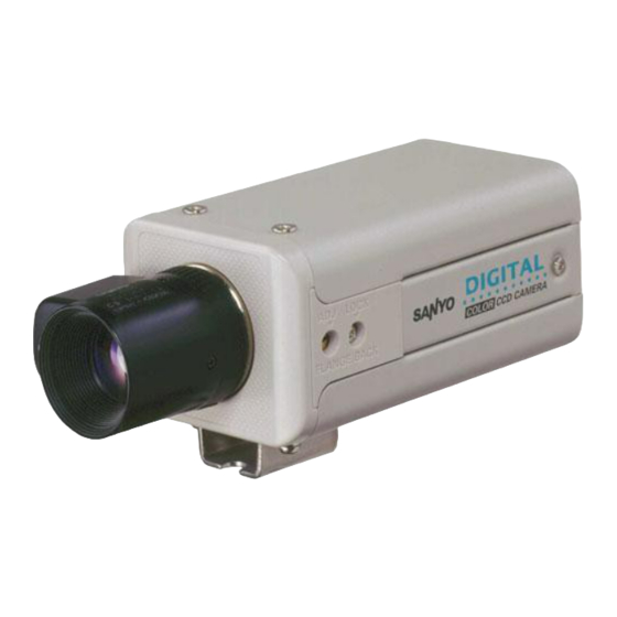
Page 7: Parts Names
L53H4/US (VCC-6594) GB 2001, 11, 9 PARTS NAMES Video output connector (VIDEO OUT: BNC type) Connect this connector to a device such as a VCR or monitor with a VIDEO IN connector. Line phase adjustment volume (LINE PHASE) When using two cameras or more, the image on the monitor may roll vertically when switching sources. This rolling can be minimized by turning this volume. - Page 8 L53H4/US (VCC-6594) GB 2001, 11, 9 PARTS NAMES Lens mount cap The cap is installed to protect the lens mount section. Remove the lens mount cap before installing a lens (sold separately). Flange-back adjustment screw (FLANGE BACK ADJ.) Flange-back lock screw (FLANGE BACK LOCK) Camera installation bracket The bracket can be fixed at the top or bottom of the camera.
- Page 9 L53H4/US (VCC-6594) GB 2001, 11, 9 PARTS NAMES Lens iris output connector (LENS) This 4-pin connector is used to send the DC control signal and power supply to an auto-iris type lens. Camera setup section (under the cover) These settings are for when using a 1/3 inch CS mount DC (without EE internal amplifier) type lens. However, if due to installation conditions or environment the settings may need to be modified for best results (see "SETTINGS").
-
Page 10: Concerning Auto-Iris Lenses
L53H4/US (VCC-6594) GB 2001, 11, 9 CONCERNING AUTO-IRIS LENSES DC type auto-iris lens VR301 A lens without amplifier circuit that operates only on a DC power source. In general, this type of lens is referred to as DC type coil lens or DC type non-amplifier lens. -
Page 11: Mounting The Lens
L53H4/US (VCC-6594) GB 2001, 11, 9 MOUNTING THE LENS Please use a DC type auto-iris lens (sold separately). Check the lens mount Do not use a lens if the length “ ” is more than mm. That may damage the camera and prevent proper installation. - Page 12 L53H4/US (VCC-6594) GB 2001, 11, 9 MOUNTING THE LENS Rewiring the lens cable in the lens iris plug Prepare the lens cable. Cut the cable at the plug, then remove approx. 8 mm of the cable sheath and strip about 2 mm from each wire.
-
Page 13: Connections
L53H4/US (VCC-6594) GB 2001, 11, 9 CONNECTIONS AC 24 V connection Push to insert the cable AC 24 V (Video signal connections) : VIDEO IN : VIDEO OUT Coaxial cable type and maximum length Basic connection for monitoring or recording •... -
Page 14: Settings
L53H4/US (VCC-6594) GB 2001, 11, 9 SETTINGS The illustration shows the factory default settings for the switches in the camera setup section. The camera settings are described on the assumption that a DC type auto iris lens is being used. If you are using a VIDEO type auto iris lens, be sure to read the Note which is given. - Page 15 L53H4/US (VCC-6594) GB 2001, 11, 9 SETTINGS Electronic shutter settings and electronic iris Table A (switch 1 ~ 3) settings 1/60(AI) 1/100 1/500 1/1000 1/2000 1/4000 1/10000 When all of these switches are down, electronic shutter (1/60 sec or auto iris setting) is enabled. The electronic shutter can be set to one of 7 speeds as shown in Table A.
- Page 16 L53H4/US (VCC-6594) GB 2001, 11, 9 SETTINGS Backlight compensation setting (MULTI mode: 64 sections) This camera has two different backlight compensation functions: Normally backlight compensation switch 6 (MULT) and 7 (CENT) are set to the down (OFF) position. Change the backlight compensation switch settings depending on the conditions.
- Page 17 L53H4/US (VCC-6594) GB 2001, 11, 9 SETTINGS White balance adjustment Lens iris adjustment Normally the switch 8 (WB) is set to the down (ATW: auto white If using a DC type auto-iris lens, you will need to set the LEVEL balance) position and the white balance is adjusted automatically.
- Page 18 L53H4/US (VCC-6594) GB 2001, 11, 9 SETTINGS Line phase adjustment When using a camera switcher to connect 2 cameras or more to one monitor, there may be a vertical roll of the images when switched. In such a case, set as described below.
-
Page 19: Troubleshooting
This camera is a precision instruments and if treated with care, will provide years of satisfactory performance. However, in the event of a problem, the owner is advised not to attempt to make repairs or open the cabinet. Servicing should always be referred to your dealer or Sanyo Authorized Service Centre. -
Page 20: Specifications
L53H4/US (VCC-6594) GB 2001, 11, 9 SPECIFICATIONS Camera: Scanning system : NTSC standard TV system Power supply : 24 V AC, 60 Hz (525 TV lines, 30 frames/sec.) Power consumption : Approx. 2.8 W (with auto iris lens) Interlace : PLL 2:1 interlace Approx. - Page 21 This file has been downloaded from: www.UsersManualGuide.com User Manual and User Guide for many equipments like mobile phones, photo cameras, monther board, monitors, software, tv, dvd, and othes.. Manual users, user manuals, user guide manual, owners manual, instruction manual, manual owner, manual owner's, manual guide, manual operation, operating manual, user's manual, operating instructions, manual operators, manual operator, manual product, documentation manual, user maintenance, brochure, user reference, pdf manual...