Advertisement
Quick Links
(UK) Limited
Premier Business Park, Croft Head Road, Off Philips Road
Whitebirk Industrial Estate
Blackburn, Lancashire England BB1 5UE
(0254) 680444
Fax (0254) 672299
Instruction and Assembly Manual
.90m, 1.0m & 1.2m SMC ANTENNA SYSTEM
AZ/EL CAP MOUNT
TYPE 900 - .9m
TYPE 100 - 1.0m
TYPE 120 - 1.2m
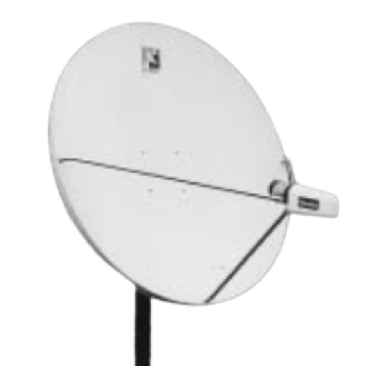
SMC ANTENNA WITH AZ/EL CAP MOUNT
WITH
1315 Industrial Park Drive, P.O. Box 1416
Smithfield, N.C. 27577 U.S.A.
(919) 989-2242
Fax (919) 989-2200
8000284
Rev. H
3/99
Advertisement

Related Manuals for Channel Master 100


Summary of Contents for Channel Master 100
- Page 1 Blackburn, Lancashire England BB1 5UE (0254) 680444 Fax (0254) 672299 WITH AZ/EL CAP MOUNT TYPE 900 - .9m TYPE 100 - 1.0m TYPE 120 - 1.2m 1315 Industrial Park Drive, P.O. Box 1416 Smithfield, N.C. 27577 U.S.A. (919) 989-2242 Fax (919) 989-2200 8000284 Rev.
- Page 2 CHANNEL MASTER shall repair or replace defective equipment, at no charge, or at its option, refund the purchase price, if the equipment is returned to CHANNEL MASTER not more than twelve (12) months after shipment. Removal or reinstallation of equipment and its transportation shall not be at the cost of CHANNEL MASTER except CHANNEL MASTER shall return repaired or replaced equipment freight prepaid.
-
Page 3: Site Selection
Be prepared to safely handle these forces at unexpected moments. Do not attempt to assemble, move or mount a dish on windy days or serious, even fatal accidents may occur. Channel Master is not responsible or liable for damage or injury resulting from antenna installations. - Page 4 FOUNDATIONS OVAL END MIN. DIA. PIER FOUNDATIONS WIND VEL. 80 MPH 90 MPH .90M 100 MPH 110 MPH 125 MPH 80 MPH 1.0M 90 MPH 100 MPH 108 MPH POLE SPECIFICATIONS: 2” SCH 40 2 ” O.D. x .154 Wall x 72” Long Steel - CM PN 611652931 w/Oval End and Powder Paint Finish.
- Page 5 PIER FOUNDATIONS #3 REBAR X DIA. OF PIER, INSERT THRU HOLE IN MIN. TUBE & CENTER DIA. OPTIONAL PIER FOUNDATIONS WIND VEL. DIM “L” DIM “A” 80 MPH 90 MPH .90M 110 MPH 68” 37” 110 MPH 125 MPH 80 MPH 90 MPH 1.0M 110 MPH...
-
Page 6: Assembly And Installation
The AZ/EL Cap Mount can be installed on a 2 ” or 3” O.D. ground tube, roof, or wall mount depending on model. The appropriate mount should be assembled and in place before installing the AZ/EL cap. As the AZ/EL cap mount is factory preassembled, there is no assembly required for the mount. - Page 7 CLAMP SURFACE Junction Block (9) FIG. 2.2 - INSTALLATION OF FEED AND FEED SUPPORT LEGS TO ANTENNA IMPORTANT: Sealing RF coaxial connector: The copper-plated center conductor in the RF coaxial cable, which connects receiver to LNB, can experience electrolysis corrosion at the LNB connector. Moisture and DC current cause this type of corrosion.To prevent corrosion, apply a mod- erate coat of silicon grease to the center conductor and then wrap the entire connection with COAX-SEAL...
-
Page 8: Antenna Alignment Procedure
Alignment with the satellite is obtained by setting polar- ization, elevation and azimuth. Charts 1, 2 & 3 are to determine the values for your earth station antenna site. “∆L” is the difference between the earth station antenna site longitude and the satellite longitude. Use “∆L” and your earth station latitude... - Page 9 " L" IS THE DIFFERENCE BETWEEN THE EARTH STATION ANTENNA SITE LONGITUDE AND THE SATELLITE LONGITUDE POLARIZATION CHART SIGN VALUES (+ OR -) ANTENNA SITE WEST OF SATELLITE LONGITUDE ANTENNA SITE EAST OF SATELLITE LONGITUDE EARTH STATION LATITUDE IN DEGREES NORTH OR SOUTH OF EQUATOR POLARIZATION CHART NORTHERN HEMISPHERE...
- Page 10 " L" IS THE DIFFERENCE BETWEEN THE EARTH STATION ANTENNA SITE LONGITUDE AND THE SATELLITE LONGITUDE EARTH STATION LATITUDE IN DEGREES NORTH OR SOUTH OF EQUATOR CHART 2...
- Page 11 " L" IS THE DIFFERENCE BETWEEN THE EARTH STATION ANTENNA SITE LONGITUDE AND THE SATELLITE LONGITUDE NORTHERN HEMISPHERE EAST WEST EARTH STATION ANTENNA LATITUDE (IN DEGREES NORTH OR SOUTH OF EQUATOR) [AZIMUTH COLUMN READING WHEN EARTH STATION IS WEST OF SATELLITE] [AZIMUTH COLUMN READING WHEN EARTH STATION IS EAST OF SATELLITE] AZIMUTH CHART CHART 3...
- Page 12 FIG. 4.0 - AZ/EL CAP MOUNT ITEM PART NO. 2070022-01 2603300-01 2460800-01 2010105-03 2503300-01 2060006-01 2070022-03 2070022-05 2020343-02 2020322-02 1010047-01 2380075-01 2380067-02 2010119-01 2509002-01 – 6010213-01 – 6010017-01 PARTS AND HARDWARE LISTING DESCRIPTION BOLT-ROUND HEAD, SQUARE NECK M8X60 WASHER-LOCK M8 ( NUT-HEX M8 HOUSING AZ/EL WASHER FLAT M8 (...
- Page 13 CLAMP SURFACE Junction Block (9) FIG. 4.1 - ANTENNA, ANTENNA FEED (LNB) & FEED SUPPORT LEGS ITEM PART NO. 2020329-07 2020329-02 2020329-03 3040642-02 3040646-02 3040681-02 6010100-05 6010100-06 6010100-07 2060008-01 2509010-01 3040667-04 2502700-01 3040663-01 2050610-20 2480600-01 VARIES 2060009-01 *Provided in feed assembly. PARTS AND HARDWARE LISTING DESCRIPTION LEG BOTTOM (.90m)
- Page 14 M8 x 60mm Round Head Square Neck Bolt Item 1, PN 2070022-01 M6 x 30mm Hex Head Bolt Item 7, PN 2060008 M4 x 12mm Phillips Head Screw PN 2430070-04 M4 x 10mm Phillips Head Screw PN 2430070 Place actual hardware on top of illustration to identify. HARDWARE SORTER M8 x 20mm Round Head Square Neck Bolt M8 x 35mm Round Head Square Neck Bolt...
Need help?
Do you have a question about the 100 and is the answer not in the manual?
Questions and answers